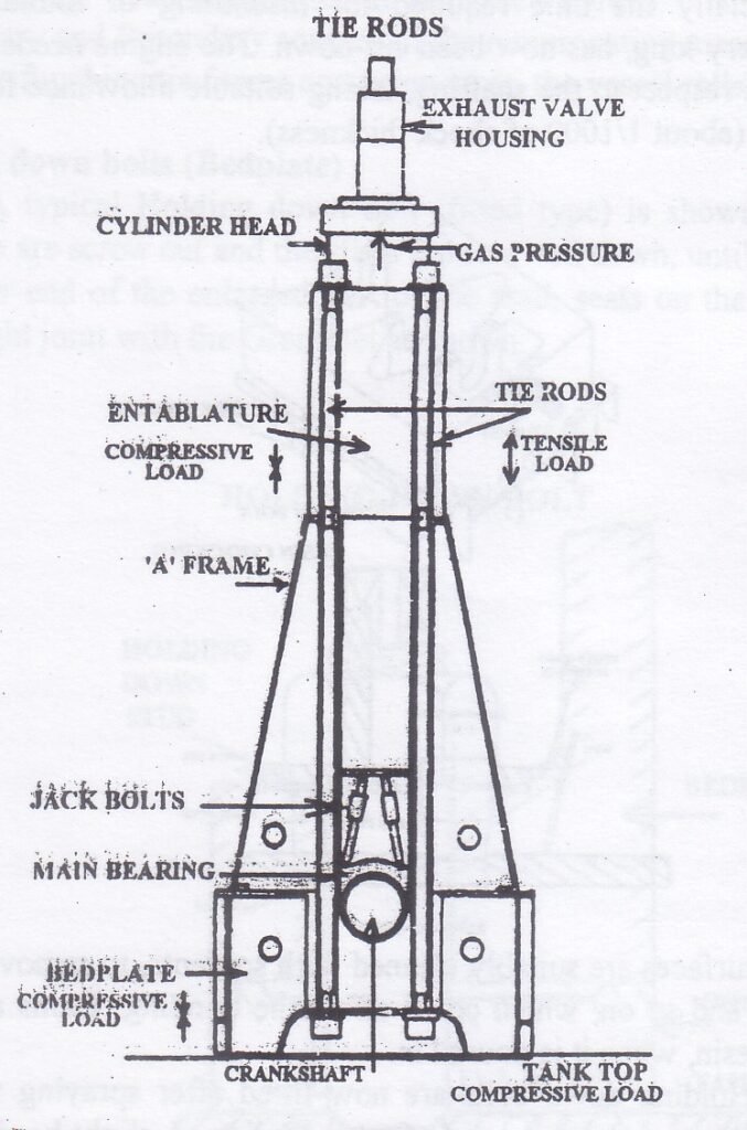
An A-frame in the context of an internal combustion (IC) engine typically refers to a structural component used in the engine’s assembly or installation, often related to mounting or support systems.
A frame in IC Engine
Key Features of A-Frames in Large Crosshead Engines:
Support for Cylinder Block: A-frames are essential for stabilizing the cylinder block, being fitted to transverse girders and ensuring the block remains firmly secured during operation.
Assembly Design:
Tie-bolts pass through these A-frames, enhancing strength and resilience.
In some designs, multiple A-frames are combined with the crankcase casing to form a rigid box structure, which is attached to the engine.
Construction:
A-frames are fabricated from flat steel plates that are welded together, creating a robust component that provides necessary support.
These frames serve as mounting points for several key engine components, including:
Crosshead guides
Main crankcase covers
Piston cooling supply pumps and return drains
Alignment and Rigidity:
A-frames are precisely aligned on the bed plate to ensure the correct positioning of all mounted components, forming a rigid structure that maintains alignment.
This assembly helps accommodate the higher lateral forces introduced by long and super long stroke engines, which use relatively short connecting rods. These rods, despite lowering the engine’s overall height, increase the angle and consequently, the lateral force component.
Construction:
Materials: Commonly made from steel or aluminum to ensure strength while keeping weight manageable.
Design: The triangular shape of the A-frame (like a capital A) provides excellent load-bearing capabilities.
Advantages of A-Frame
Greater Structural Rigidity: Provides enhanced strength and stability to withstand operational stresses.
More Accurate Alignment: Ensures precise alignment of the crosshead, which is crucial for engine efficiency and longevity.
Uniform Force Distribution: The design allows for a more uniform distribution of forces, leading to a lighter structure without compromising strength.
Improved Oil Tightness: The robust construction helps maintain seals and improve oil retention, enhancing engine performance and reducing leaks.
The UMS (Unmanned Machinery Space) requirements, as outlined in the SOLAS (Safety of Life at Sea) regulations from 1977, are essential for ensuring the safety and functionality of vessel machinery while minimizing the need for crew presence in machinery spaces.
Here’s a concise summary of the UMS requirements you mentioned:
UMS Requirements
1.Bridge Control of Propulsion Machinery:
The watchkeeping officer must have the ability to take emergency control actions.
Control systems should be simple and user-friendly.
2.Centralized Control and Instrumentation:
Centralized controls in the machinery space must allow for quick access in emergencies.
Controls must be comprehensive and easily reachable.
3.Automatic Fire Detection System:
Alarms and detection devices should operate rapidly.
Multiple well-partitioned detectors must be installed for quick response.
4.Fire Extinguishing System:
In addition to hand-held extinguishers, a remote control fire station is essential.
The station should provide control over pumps, generators, quick-closing valves, ventilation, and extinguishing media.
5.Alarm System:
A comprehensive alarm system must be established for the control of the accommodation area.
6.Automatic Bilge High-Level Fluid Alarm and Pumping Units:
Bilge sensing devices must have alarms and automatic pump activation/deactivation.
7.Automatic Start of Emergency Generator:
Emergency generators should be connected to a separate busbar and primarily serve to prevent blackouts.
8.Local Planned Control of Essential Machinery:
Controls should be significantly localized for immediate access and management.
9.Adequate Settling Tank Storage Capacity:
Properly designed storage systems must be in place for pollutant management and system efficiency.
10.Designed Safety Systems:
Systems should automatically isolate malfunctioning segments and restore control.
11.Steering Gear Operations:
Features should allow for shutdown in case of serious malfunctions.
Stand-off options and load-sharing mechanisms should be implemented for auxiliary engines.
12.Deadman Alarm:
An alarm system to ensure that vessels can detect operator incapacitation or emergencies.
These requirements help ensure that the vessel can operate safely and efficiently without the constant presence of crew members in the machinery space, while also preparing for emergencies where human intervention is necessary. If you have further specific queries regarding these requirements, feel free to ask!
Difference between Crosshead and Trunk type Piston engine
Difference between crosshead and trunk type Piston engine are as follows :-
Crosshead Type Engine
It looks like you’d like the crosshead type engine section expanded with the details you provided. Here’s a refined version in a formal tone that aligns with the earlier structure of the blog post:
Crosshead Type Engine: Design and Features
Connecting Rod and Piston Rod A defining feature of the crosshead type engine is the presence of both a connecting rod and a piston rod. The piston rod connects the piston to the crosshead assembly, which in turn is connected to the connecting rod. This distinction separates crosshead engines from trunk type engines, which lack a piston rod.
Diaphragm Separation Crosshead engines are equipped with a diaphragm that separates the cylinder space from the crankcase. This feature prevents the mixing of lubricants, allowing for different lubrication systems to be used in the cylinder and the crankcase, thus enhancing overall engine performance and longevity.
Bearing Assembly at the Upper Part In the upper part of the crosshead engine, the connecting rod is linked to the crosshead assembly. This assembly, which consists of a crosshead block, pins, and slippers, plays a critical role in ensuring smooth movement and transferring forces efficiently. The crosshead assembly connects to the lower part of the piston rod, which is rigidly fixed to the piston, creating a solid structure that minimizes stress and wear.
Separate Cylinder Lubrication One of the key features of the crosshead engine is its separate lubrication system for the cylinder and the crankcase. The cylinder uses a distinct oil from the crankcase, tailored specifically for the high-temperature environment of the cylinder. This system enhances the engine’s efficiency and prolongs its lifespan.
Transverse Force Management The transverse forces generated by the oscillation of the connecting rod are managed by the crosshead and its guides. These forces are transmitted through the crosshead guides to the engine structure, reducing wear on the piston and piston rod assembly.
Crosshead Assembly as a Connecting Mechanism The crosshead assembly is a critical connecting mechanism between the piston rod and the connecting rod. The piston is rigidly fixed to the piston rod, and this rigid connection ensures that forces are efficiently transmitted from the piston to the connecting rod via the crosshead assembly.
Higher Torque at Low Speeds Crosshead engines are capable of generating higher torque at lower speeds, making them ideal for applications requiring heavy-duty, low-speed performance. This is a key advantage in marine propulsion systems and other industrial applications where low-speed operation is crucial.
Increased Height Requirements Due to the complexity of the crosshead assembly and the inclusion of both a piston rod and a connecting rod, crosshead engines require more vertical space. For the same power and speed, a crosshead engine will have a taller profile than a trunk type engine.
Transverse Thrust Transmission The transverse thrust generated within the engine is effectively transmitted to the engine structure through the crosshead guides, which absorb and manage these forces. This ensures that the engine operates smoothly without excessive stress on the moving parts.
Higher Manufacturing Costs The complexity of the crosshead assembly and the need for separate lubrication systems contribute to higher manufacturing costs. The additional components and engineering precision required make these engines more expensive to produce, though they offer superior durability and performance under demanding conditions.
More Height for Same Power and Speed As mentioned earlier, due to their complex structure, crosshead engines require greater height for the same power and speed when compared to trunk type engines. This can be a limitation in applications where space is a critical factor.
Efficient Use of Low-Grade Fuel Crosshead engines are designed to handle low-grade fuels efficiently, as their operation at lower speeds allows more time for complete combustion. This ability makes them ideal for applications where fuel cost savings are a priority.
Trunk type engine
It looks like you’re reiterating the details of the trunk type engine. Here’s a refined version in formal tone that incorporates your points:
Trunk Type Engine: Design and Features
Absence of a Piston Rod In a trunk type engine, only the connecting rod is present, directly connecting the piston to the crankshaft. There is no piston rod, which simplifies the engine design. This contrasts with crosshead engines, which have both a connecting rod and a piston rod.
No Diaphragm Unlike crosshead engines, the trunk type engine has no diaphragm separating the cylinder from the crankcase. As a result, there is no physical barrier between the two, which allows for a unified lubrication system.
Direct Connection to Piston via Gudgeon Bearing Assembly The upper part of the connecting rod in a trunk type engine is connected directly to the piston through a gudgeon bearing assembly. This eliminates the need for additional components like a crosshead, simplifying the engine structure.
Unified Lubrication System In trunk type engines, the same lubrication oil is used for both the cylinder and the crankcase. While this simplifies maintenance, it can potentially result in increased wear due to the mixed operating conditions.
Piston Skirt Absorbs Transverse Thrust The piston skirt in trunk type engines absorbs the transverse thrust caused by the oscillation of the connecting rod. This function, performed by the crosshead assembly in crosshead engines, is managed by the piston skirt in trunk engines.
No Crosshead Assembly In trunk type engines, the connecting rod is attached to the piston via a gudgeon pin, and there is no crosshead assembly. This significantly reduces the complexity of the engine compared to the crosshead type.
High Power at Medium or High Speeds Trunk type engines are designed to operate efficiently at medium to high speeds, where they produce high power output. This makes them suitable for applications where speed is a critical factor.
Compact Design and Reduced Headroom One of the advantages of trunk type engines is their compact design. They require less headroom compared to crosshead engines because there is no piston rod or crosshead assembly. This makes them ideal for installations where space is limited.
Piston Skirt Handles Side Thrust The side thrust created by the movement of the crankshaft and connecting rod is absorbed by the piston skirt in trunk type engines. This design concentrates the mechanical stress on the piston, requiring the skirt to be strong enough to withstand these forces.
Lower Manufacturing Costs Trunk type engines have lower manufacturing costs due to their simpler design and fewer components. The absence of a crosshead assembly and diaphragm reduces the complexity of the engine, making it more cost-effective to produce.
Less Height for Same Power and Speed Due to the simplified design, trunk type engines require less vertical space for the same power output and speed compared to crosshead engines. This reduction in height is a significant advantage in applications where space constraints are a factor.
Efficient Use of Low-Grade Fuel Trunk type engines can efficiently use low-grade fuels, making them cost-effective in operations where fuel quality is variable. The engine’s ability to run efficiently on such fuels provides flexibility in fuel choices depending on operational requirements.
Here a Very Easy table comparing crosshead type engines and trunk type engines based on the information you’ve provided:
Feature
Crosshead Type Engine
Trunk Type Engine
Piston Rod
Has both a connecting rod and a piston rod.
Only the connecting rod; no piston rod.
Diaphragm
Has a diaphragm separating the cylinder from the crankcase.
No diaphragm.
Upper Part Connection
Connecting rod is connected to the piston rod via a crosshead assembly.
Connecting rod is directly connected to the piston via a gudgeon bearing assembly.
Lubrication System
Separate oils for cylinder and crankcase.
Same lube oil used for both the cylinder and crankcase.
Transverse Thrust Absorption
Transverse thrust is absorbed by the crosshead and its guide.
Transverse thrust is absorbed by the piston skirt.
Crosshead Assembly
Has a crosshead assembly connecting the piston rod to the connecting rod.
No crosshead assembly; uses a gudgeon pin to connect the connecting rod to piston.
Performance
Develops high torque at low speeds.
Produces high power at medium or higher speeds.
Space Requirements
Requires more height due to complex structure.
Requires less headroom; more compact design.
Transverse Thrust Handling
Thrust is transmitted to engine structure through crosshead guides.
The piston skirt handles the side thrust.
Manufacturing Costs
Higher due to complexity and additional components.
Lower due to simpler construction.
Height for Same Power and Speed
More height needed for the same power and speed.
Requires less height for the same power and speed.
Fuel Efficiency
Can efficiently use low-grade fuel over time due to longer combustion.
Can also use low-grade fuel efficiently, suitable for various applications.
This table provides a clear and easy comparison between the two engine types. Let me know if you’d like to adjust or add more details!
A type of an internal combustion engine in which the connecting rod is directly connected to the piston by Gudgeon pin (also called piston pin ).
Advantage of crosshead type engine ?
Advantage are :-
The Cross head type engine are able to devlop higher power at lower rotational speed of the engine than trunk type engines.It is because the space available for the crosshead bearing is greater than the space within the piston for gudgeon bearing assembly.
The combustion product contamination of crankcase lube oil is less than the trunk type engine.
Total costs of lubricants of crosshead engine is less than the trunk type engine having same power.
What is a cross head engine ?
Why do pistons have skirt ?
Skrt do two functions
1.The piston skirt consists of spaces for gudgeon pin which transmits power to the con. rod
2.The skirt also help in transmitting the side thrust produced by the connecting rod.
What is the name the portion below the piston boss?
Ans :- Skirt ring belt: is the upper-middle part of the piston when the piston rings are located.
pin
boss: is the lower-middle part of the piston which contains the piston pin.
What are the 3 types of piston rings?
Why crosshead lubrication is difficult?
What is the largest diesel engine in the world?
What is a cross head type diesel engine?
What is a crosshead bearing? a sliding member of a reciprocating engine for keeping the motion of the joint between a piston rod and a connecting rod in a straight line.
Can you use a piston with a broken skirt?
Nope, no good, never, shouldn’t even think about it, NOT IN ANY ENGINE. That’s just asking for more damage or destruction.
Difference between Water Tube Boiler and Fire Tube Boiler
In today’s article we are going to learn about the difference between water tube boiler and fire tube boiler or in simple words Fire Tube Boiler Vs Water Tube Boiler.
We know that boiler is used onboard for power generation and it is one of the most important thing on ship.
Boiler is broadly categorised into water tube boiler and fire tube boiler. And since they are categorised differently this means that there must be some differences between them either in functioning, maintaining, running or economical differences. This article is all about their differences.
Fire Tube Boiler Vs Water Tube Boiler
Water Tube Boiler
Fire Tube Boiler
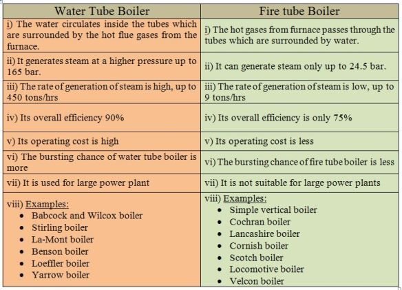
1. The water flows inside the tube and the hot combustion gases flows outside the tube.
1. The hot gases flows inside the tube and the water is outside the tube.
2. These are generally high pressure boiler ranging up to 70-100 Bar.
2. These are generally low or medium pressure boiler up to 25 Bar.
3. Faster rate of steam Production.
3. Lower rate of steam Production.
4. More efficient
4. Less efficient
5. These boilers are mostly externally fired.
5. These are internally fired. The furnace is placed at one end of the Fire tube.
6. Suitable for large scale power plants.
6. Suitable for small scale power plants.
7. Since the operating pressure is high, the risk of explosion is also high.
7. Risk of explosion is less, as less operating pressure.
8. Occupies less floor space.
8. Occupies large floor space.
9. Because of complexity, skilled person is required to operate.
9. Less complex, less skill required.
10. Easy to clean as it is externally fired
10. Difficult to clean as internally fired.
11. The shell diameter is less.
11. The diameter of shell is more.
12. Easy to carry out maintenance.
12. Difficult to carry out maintenance
13. Since water flows inside the tube, treatment of water is necessary to prevent deposit formation.
Difference between water tube boiler and fire tube boiler in a descriptive format | Fire Tube Boiler Vs Water Tube Boiler
Fire Tube Boiler
In fire tube boiler, as the name suggest Fire Tube (i.e Fire in Tube) the hot combustion gases ( flue gases) are passed through the tubes which are arranged inside the cylindrical drum and the outside of the tubes are surrounded by the water.
The heat transfer takes place between the hot gases and the surrounded water through the tubes. This heats up the water and convert it into steam. Fire Tube boilers are simple in construction as compared water tube boilers and are used as their alternative because of being cheaper.
These are generally used in small scale industries as the operating pressure of fire tube boilers are low.
Other advantages of fire tube boilers are that they have compact size and have the ability to handle the fluctuations in steam demand more efficiently. There are also certain disadvantages of Fire tube boiler like it’s efficiency is low, it takes longer time to convert that amount of water into the steam, not able to cope up with sudden increase in load.
Water Tube Boiler
Now coming to the water tube boiler (i.e water in the tube), the water runs inside the tube and the hot gases are passed over the outer surface of the tube.
The heat is transferred from the hot gases to the water in the tubes and it gets converted into steam.
Since the steam is generated in the tubes , the water tube boilers can operate at higher pressure than the fire tube boilers and hence they are used in large scale production that requires high pressure and high steam output.
Advantages
Water tube boilers are generally provided with more than one burner and we can use these burner either individually or in parallel combination for a single furnace.
This provides a way to have controlled shutdowns so that maintenance can be carried out without shutting off the boiler entirely.
Also the burners can be used to operate at different loads. Water tube boilers are also provided with Programmable Logic Controller for controlling and maintaining proper functioning of the burners provided.
They also control the super heater and feed water systems. As the volume of area of production of steam is less in water tube boiler the water tube boilers are able to produce high pressure steam and at a faster rate than the fire tube boiler.
They can also produce super heated or saturated steam according to the design and the place where they are required. They are able to operate at higher pressure. The water tube boiler can be constructed to use high-ash fuels in conjunction with the soot blowers and proper Ash handling and flue gas cleanup equipment to maintain environmental regulations.
Disadvantages
Though we have seen the various advantages of the water tube boiler but there are certain disadvantages also.
The capital cost of water tube boiler is very high and the size of the water tube boiler is large as compared to fire tube boiler which bring it to a point that it is mostly constructed on the site where it has to be used. Because of the use of control systems the complexity and it’s cost increases more.
And for working on it a proper training is required. Now that we have seen the descriptive difference between water tube boiler and fire tube boiler.
Now it is more easy to remember in point form rather than the description, though the description gives you a better understanding of the differences.
People also ask
Which is better fire tube boiler or water tube boiler?
Between the two types of boiler, Water tube boilers are more significantly more efficient than fire tube.
It will be clear you after reading following reasons :-
1.Water converts into steam very Quickly. When the water flow through the tubes ,it is only surrounded by heat rather than the other way around.
Since the tube holds less water than the tank of fire tube boiler so ,it takes less time to convert that water into steam and thus less consumption of fuel.
The water tube boiler did the work of producing steam in as little as five minutes, compared to an hour or more for the fire tube boilers. As a result, fuel savings costs can be significant over time
2.Water tube boilers require less water. By heating water in the tube via a once-through design, water tube boilers don’t need to store as much water to produce steam, making them more environmentally friendly by design.
3.Water-tube boilers can adapt to change loads more easily. Water tube boilers can respond more quickly to changes in demand for steam, by heating less water at one time.
Individual units configured modularly can power up or down as required. This means we only use fuel and water as needed, greatly reducing energy waste in the process.
4.Water tube boilers seem to last longer. The ability to operate more effectively also ensures that boilers for water tubes have a longer life expectancy than their counterparts for fire tubes.
Where are water tube boiler used ?
Water tube boilers are most commonly used where high pressures of steam are required and may exceed 3,000 psi.
Water tube boilers can generate saturated or superheated steam that is useful for applications such as steam turbine power generation. In addition, such boilers are commonly used in process industries, including chemical, refining and pulp and paper manufacturing.
Why water tube boiler is more efficient than fire tube boiler ?
In fire tube boilers, flue gases need to heat up a large amount of water and are therefore slow and inefficient.
Because of their slow operation, more heat is lost to the surroundings. In the water tube boilers, flue gases pass through the water tubes and deal with less water.
They’re fast in operation, therefore, and less heat is wasted in the surroundings.
So, They’re more efficient.
Why can’t a fire tube boiler be made with a high capacity as a water tube boiler ?
Fire tube boilers are used for small capacity & less pressure boilers because the heat is explored to evaporate the water is less available also the heat is less available. But in the water tube Boilers area available to heat the water is more because the flue gas flows around the tubes. It is therefore used for higher capacity and high pressure of approximately 127 Kg/cm2 or more.
What are the differences between a tank boiler and a water tube boiler?
You may be referring to “Fire-tube” vs. “Water tube” In the former, the entire tank is filled with pressurized water and steam with fire flowing through the tank in pipes. This form is no longer used except in historic installations.
Excessive pressure due to technological malfunction or operator error may cause the entire tank to burst, killing people nearby. The sort of water pipe will never explode because all the pressure is in the pipes and the tank has hot gases. If the tube splits, the steam spills harmlessly into the firebox.
So these were some of the basic difference between Water tube Boiler and Fire tube Boiler which are covered in this article in tabular as well as descriptive form. Fire Tube Boiler Vs Water Tube Boiler is one of the common things that people generally ask. If You liked this article, please share it with your friends and give your feedback in the comment below.
Difference between pressure relief valve and pressure safety valve: When discussing pressure in process industries, two important safety devices often come up: Pressure Safety Valves (PSVs) and Pressure Relief Valves (PRVs). While these terms are commonly used interchangeably, it’s important to understand that they have distinct differences, despite serving similar functions.
Difference between PV Valve and PV Breaker : The Pressure Vacuum (PV) Valve and the Pressure Vacuum (PV) Breaker are critical safety devices used on ships, especially on oil tankers, to regulate and maintain safe pressure levels within cargo tanks. While both devices play a role in preventing overpressure or vacuum conditions, they operate under different circumstances and serve different purposes.
What is pressure vacuum (PV Valve ) and pressure vacuum (PV ) Breaker ?
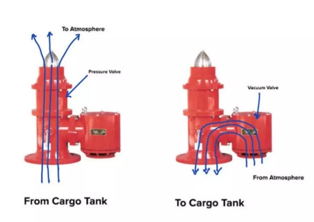
Pressure Vacuum (PV) Valve: A Pressure Vacuum Valve (PV Valve) is a device used to maintain a balanced pressure in a cargo tank during loading, discharging, or transportation of cargo. It ensures that the tank does not experience dangerous overpressure or underpressure conditions, which could potentially lead to ruptures or implosions. The PV valve opens when the tank pressure exceeds the safe limit or falls below a certain threshold, allowing gases to escape or air to enter, keeping the tank safe and intact.
Pressure Vacuum (PV) Breaker: A Pressure Vacuum Breaker (PV Breaker) is a safety device installed in the inert gas (IG) line on a ship’s deck. It ensures that the pressure in the system stays within safe limits, preventing the buildup of excessive pressure or creating a vacuum condition in the IG line. This is important for protecting the cargo tanks and the ship’s structure from potential damage. The PV Breaker acts as a backup for the PV Valve, ensuring additional safety by breaking any excessive vacuum or pressure in the system.It is a safety devices which is used in IG Line on Deck.
Function of pv valve and Pv breaker
Here are the functions of both the Pressure Vacuum (PV) Valve and the Pressure Vacuum (PV) Breaker:
Functions of PV Valve:
Maintaining Pressure and Vacuum: The PV valve ensures that the cargo tank maintains a balanced pressure during loading and unloading operations.
Preventing Overpressure: It releases excess pressure from the tank to prevent overpressure conditions, which could damage the tank.
Preventing Underpressure: It allows air or gas to enter the tank to prevent underpressure (vacuum) conditions that could collapse the tank.
Functions of PV Breaker:
Handling Abnormal Pressure Increases During Loading: The PV breaker opens to relieve abnormal pressure increases when the gas outlet rate from the tank is insufficient during cargo loading.
Handling Abnormal Pressure Increases During Discharge: When cargo is discharged at a higher rate than the inert gas blower can replace, the PV breaker prevents pressure buildup in the tank.
Dealing with Breather Valve Malfunction: In case the breather valve fails to operate due to pressure fluctuations (caused by changes in atmospheric or seawater temperatures), the PV breaker steps in to stabilize the tank’s pressure, either releasing or admitting gas as necessary.
Both devices are crucial for maintaining safe operating conditions within cargo tanks.
Difference Between PV Valve and PV Breaker
Let’s break down the key differences between the PV Valve and the PV Breaker from various points of comparison.
Overview:
The Pressure Vacuum (PV) Valve and the Pressure Vacuum (PV) Breaker are critical safety devices used on ships, especially on oil tankers, to regulate and maintain safe pressure levels within cargo tanks. While both devices play a role in preventing overpressure or vacuum conditions, they operate under different circumstances and serve different purposes. Let’s break down the key differences between the PV Valve and the PV Breaker from various points of comparison.
Difference between PV Valve and PV Breaker:
Point of Comparison
PV Valve
PV Breaker
Function
Maintains safe pressure and vacuum in individual cargo tanks during normal operations such as loading and unloading.
Handles abnormal increases in pressure or vacuum when the PV valve is unable to cope, providing backup for excessive pressure surges.
Location
Installed on each cargo tank individually.
Installed on the inert gas (IG) line on the deck, serving all cargo tanks.
Operating Pressure
Operates at 1400 mm of water column (0.14 bar) and vacuum of -250 mm of water column (-0.025 bar).
Operates at 1600 to 1800 mm of water column (0.16 to 0.18 bar) and vacuum of 400 mm of water column (-0.04 bar).
Primary Role
Ensures normal pressure control in the cargo tank during loading, discharging, and transportation.
Acts as a safety backup when pressure or vacuum exceeds the PV valve’s capacity, preventing dangerous tank conditions.
Handling Rate of Loading
Handles pressure adjustments during normal cargo loading and discharging rates.
Handles rapid and abnormal increases in pressure due to fast loading rates or equipment failure.
Response to Vacuum
Opens to let air into the tank if vacuum conditions occur, ensuring the tank doesn’t collapse.
Operates when the vacuum exceeds the PV valve’s limits to protect the system from extreme vacuum conditions.
Number of Devices
Typically, one PV valve per cargo tank.
Typically, only one PV breaker per system, serving all tanks via the IG line.
Design Objective
Primarily designed for normal operational safety.
Designed to handle emergency situations when the pressure exceeds normal levels or when equipment (like the breather valve) malfunctions.
On basis of operating pressure
Based on the operating pressures measured in terms of water column (mm of water column):
Pressure Vacuum (PV) Valve:
Operating Pressure:
The PV valve operates at 1400 mm of water column (which is approximately 0.14 bar).
It also operates at a vacuum of -250 mm of water column (approximately -0.025 bar). This means the valve opens to relieve pressure when it reaches 1400 mm water column and allows air in when the vacuum reaches -250 mm.
Pressure Vacuum (PV) Breaker:
Operating Pressure:
The PV breaker operates between 1600 mm to 1800 mm of water column (which is approximately 0.16 to 0.18 bar).
It operates at a vacuum of 400 mm of water column (approximately -0.04 bar). The PV breaker is designed to activate when the pressure or vacuum exceeds the capacity of the PV valve, handling higher pressure surges or stronger vacuum conditions.
Conversion Note:
As a reference:
1000 mm of water column ≈ 0.1 bar
This helps in converting between pressure in mm of water column and bar as needed.Image
When and where Pv breaker and pv valve is used
Where and When PV Valve is Used:
Location: An individual PV Valve is installed on each cargo tank. It directly controls the pressure and vacuum within that specific tank.
Usage:
During loading and unloading operations, where pressure fluctuations can occur.
The PV valve automatically responds to minor pressure or vacuum changes in the tank. If the internal pressure drops below a certain level, the valve opens downward, allowing external air or gas to enter the tank. If the pressure inside the tank exceeds a certain limit, the valve opens upward, allowing gases to escape.
It works under normal operating conditions to maintain the balance between internal and external pressure.
Where and When PV Breaker is Used:
Location: Typically, only one PV breaker is fitted in the inert gas (IG) line on the deck of the ship, servicing all cargo tanks through the IG system.
Usage:
The PV breaker is used in situations where there is an abnormal pressure increase that exceeds the handling capacity of the PV valve.
This occurs when cargo is loaded at a high rate, causing a rapid increase in pressure that could lead to an explosion if not relieved.
The PV breaker opens to relieve the excess pressure when the loading rate or inert gas blower is beyond the specified limit.
It also activates if there is a malfunction in the PV valve or breather valve, ensuring the safety of the cargo tanks.
In essence, PV valves handle normal operational pressure adjustments, while the PV breaker acts as a safety backup for extreme pressure surges.
What pressure it maintains
The pressure ranges maintained by the PV Valve and PV Breaker are as follows:
PV Valve:
Pressure Range:
For large oil tankers, the PV valve typically maintains the tank pressure between 0.07 to 0.20 bar.
It ensures that minor pressure fluctuations are controlled, keeping the tank pressure within this range during normal operations like loading and unloading.
PV Breaker:
Pressure Handling:
The PV breaker is designed to handle pressure surges beyond the capacity of the PV valve.
It activates if the pressure rises to 0.24 bar (maximum), relieving the excess pressure and preventing any damage to the cargo tanks.
In summary, the PV valve handles normal pressure regulation, while the PV breaker comes into play when the pressure rises abnormally, ensuring safety beyond the operational limits of the PV valve.
Summary
The PV valve manages everyday pressure and vacuum conditions within each cargo tank, ensuring safe operations during cargo loading and unloading.
The PV breaker steps in during emergency situations when pressure or vacuum conditions become abnormal, acting as a secondary safeguard for the entire cargo system.
A duplex strainer, also known as a twin basket strainer, is a type of filter that is installed in a gas, oil, or water piping system to remove large particles of dirt and debris. In most cases, a duplex strainer system consists of two separate housings for strainer baskets. A valve handle is also included between the two boxes to redirect liquid flow to one strainer while the other is being cleaned.
In some strainers, the valve will operate automatically, and the strainer will perform a self-cleaning method.
These kind of strainers are used in pipeline systems when the flow cannot be stopped. They can filter up to 40 µm depending on the size of their NB. Basket strainers are used in industries where the majority of the pollutants are solids. These strainers, unlike other types of strainers, are very simple to maintain.
Duplex Strainer Working Principle
The working principle of a duplex strainer is based on allowing continuous filtration of liquids while providing an option for maintenance or cleaning without interrupting the system. It consists of two filter chambers, each containing a perforated basket or mesh that captures debris and particles from the fluid. During operation, liquid flows into one of the chambers, where the strainer basket filters out unwanted particles, and the cleaned liquid then exits the system.
A key feature of the duplex strainer is the changeover valve, which enables operators to switch the flow from one chamber to the other. When one filter becomes clogged, the flow is diverted to the second, clean chamber, allowing the clogged filter to be cleaned or replaced without stopping the system.
This continuous operation ensures that the system can keep running without downtime. Once maintenance on the clogged filter is completed, the cleaned chamber can be brought back into use. Duplex strainers are commonly employed in applications that require the protection of equipment, such as pumps and valves, from debris while maintaining uninterrupted flow.
How does a Duplex Strainer Work?
A Duplex strainer, or a Basket strainer, is made up of two distinct strainer baskets that are housed together. The suspended solids are trapped in a cleanable basket. A valve handle is put between the two baskets to restrict the flow of liquid to one strainer while the other is being cleaned. Butterfly valves are used to change the flow direction.
Lube oil system uses duplex filters. Only one filter is used at a time, while the other is kept clean.
What is the purpose of Duplex Strainer?
These strainers or filters are used where the flow of the fluid cannot be stopped. For example in Fuel Lines, Lube Oil lines etc where if the flow is stopped, it can lead to fatal failure of engines and equipments.
Cleaning of Duplex Filter
Filters are cleaned on a regular basis or whenever there is a pressure drop. To clean the filter, flip the filter over to the clean side.
Open the purge cock on the filter you’re using and make sure oil is flowing through it.
Open the filter’s purge cock which is not in use. After the oil has stopped flowing, open the cover and remove the filter element.
When using heavy fuel oil, use caution because it will be quite hot. The filter is made up of notched wire. The size of the notched wire is determined by the micron rate of filtering. It ranges in size from five to 35 microns.
Using kerosene and compressed air, clean the filter element. Replace the filter element and lid, then slowly switch over and expel the air from the filter housing.
How do self cleaning filters work?
Self-cleaning filters clean themselves by utilizing system pressure. The filter’s rigid cylinder screen strains particles from the water source, keeping the material inside.
This buildup can result in a pressure difference between the inlet and the outlet. A flush valve opens when the pressure differential reaches the set control (usually approximately 7psi). This produces a low-pressure flow, which allows the suction nozzles to vacuum the particles out of the filter.
Advantages of Self-Cleaning Filters
Automatic self-cleaning filters have a number of benefits, the most important of which is that they are low-maintenance, making them a great choice for remote sites because they do not require operator participation.
Another significant advantage of industrial self-cleaning filters is that they clean themselves while the system is still in operation. The user saves money, energy, and time as a result of this. They also usually feature a compact form that allows for installation flexibility.
Gating System – Definition, Function, Types, Diagram: Gating System is an important concept in casting process. Through this article we will learn What is gating system, types of gating system and at the end there are some MCQs related to the topic like what happens if If the gating system is part of the pattern. Let’s start with the Definition.
What is Gating System in Casting
The term gate is defined as one of the channels which actually leads in the mould cavity, and the term gating or gating system refers to all channel by means of which molten metal is delivered to the mould cavity.
Functions of a Gating System
The functions of a gating system are :
To provide continuous, uniform feed of molten metal, with little turbulence as possible to the mould cavity. Excessive turbulence results in the aspiration of air .
To supply the casting with liquid metal at best location, achieve proper directional solidification and optimum feeding shrinkage cavities.
To fill the mould cavity with molten metal in the short possible time to avoid temperature gradient.
To provide with a minimum of excess metal in the gates and risers. Inadequate rate of metal entry, on the other hand, will result many defects in the casting.
To prevent erosion of the mould walls.
To prevent slag, sand and other foreign particles from entering the mould.
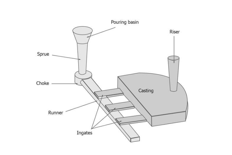
Gating System
Gating System
A gating system is usually made up of (1) Pouring Basin (2) Sprue (3) Runner and (4) Flow–off Gate. They are shown in Fig.
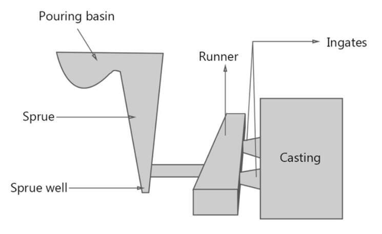
1. Pouring basin – Elements of Gating System
Pouring Basin
Pouring basin : – This part of the gating system is made on the top of the mould. Sometimes, a funnel-shaped opening which serves as pouring basin, is made at the top of the sprue in the cope. The main purpose of the pouring basin is to direct the flow of metal from ladle to the sprue, to help maintaining the required rate of liquid metal flow, and to reduce turbulence and vortexing at the sprue entrance.
The basin should be made substantially large and should be placed near to the edge of the moulding box to fill the mould quickly. Also, it must be deep enough to reduce vortex formation and kept full during the entire pouring operation to compensate metal shrinkage or contraction.
2. Sprue – Elements of Gating System
Sprue
Sprue : The vertical passage that passes through the cope and connects the pouring basin with the runner or gate is called the sprue.
The cross-section of a sprue may be square, rectangular, or circular. The sprues are generally tapered downward to avoid aspiration of air and a metal damage. Sprues up to 20 mm diameter are round in section whereas larger sprues are often rectangular. A round sprue has a minimum surface exposed to cooling and offers the lowest resistance to the flow of metal. In a rectangular sprue, aspiration and turbulence are minimized.
3. Runner – Elements of Gating System
Runner : In large castings, molten metal is usually carried from the sprue base to several gates around the cavity through a passageway called the runner. The runner is generally preferred in the drag, but it may sometimes be located in the cope, depending on the shape of the casting. It should be streamlined to avoid aspiration and turbulence.
4. Gate – Elements of Gating System
Gate : A gate is a passage through which molten metal flows from the runner to the mould cavity. The location and size of the gates are so arranged that they can feed liquid metal to the casting at a rate consistent with the rate of solidification. A gate should not have sharp edges as they may break during passage of the molten metal and consequently sand particles may pass with the liquid metal into the mould cavity. However, the gates should be located where they can be easily removed without damaging the casting.
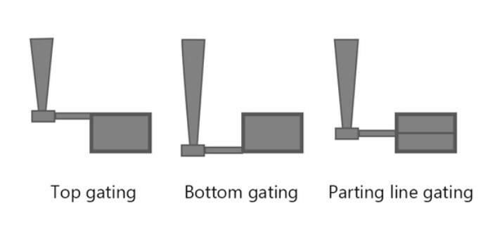
Types of Gates
According to their position in the mould cavity, gating may be broadly classified as (1) top gating, (2) parting-line gating, and (3) bottom gating. Different types of gating systems in casting process are :
Types of Gates in Gating System
Top gates
In top gating system, the molten metal from the pouring basin flows down directly into it. A strainer, made of dry sand or ceramic material, is mostly used at the pouring basin to control the metal flow and to allow only clean metal to enter.
In the case of light castings, wedge-shaped gates called wedge gates may be provided. For massive iron castings, pencil gates are used. In this type of gating, the sprue is made up of a series of slits fed from a pouring cup. It does control the rate of metal flow since the weight of molten metal is divided equally into its various slits or branches thus reducing the effective weight of head to a great extent. Moreover, slag (or dross) gets removed from the liquid metal in the pouring cup over the gate.
In the finger gate, a modification of the wedge gate, the metal is again allowed to reach in a number of streams. The ring gate uses a core to break the fall of the molten metal and sends the molten metal in the mould in proper position, and at the same time retains the slag.
The advantage of top gating is that all metal enters the casting at the top, and the hottest metal therefore comes to rest at the top of the casting. As a result, proper temperature gradients favorable for directional solidification towards the risers located on the top of the casting are attained. The gates themselves may be made to serve as the risers. The disadvantage of top gatingsystem is the erosion of the mould by the falling metal . The mould cavity should, therefore, be hard and strong enough to resist the impact.
Parting gates
In parting line gates, the liquid metal enters the mould cavity from the side of the mould at the same level as the mould joint or parting line. The arrangement of providing a gate at the parting line in a direction horizontal to the casting allows the use of devices that can effectively trap any slag, dirt, or sand, which passes with the metal down the sprue.
Skimming gate
In a skimming gate, any foreign matter which is lighter than the parent metal rises up through the vertical passage of the skimming gate and is thus trapped. Parting line gate with skim bob and choke is used to trap the slag and foreign matter in the mould and to serve as a restriction to control the rate of flow of the metal.
Another effective method to trap the slag is to use a skimming gate with a whirlpool runner, usually called whirlpool gate. The slag, due to whirlpool action, comes to the center from where it rises up in the whirlpool gate. Gate with shrink bob serves the dual function of slag-or dross-collector and as a metal reservoir to feed the casting as it shrinks.
Parting line gates in the gating systems are very simple to construct, and very fast to make. They produce very satisfactory result when the drag is not very deep, and prove to be very advantageous when they can be fed directly into the riser. In this system, the hottest metal reaches the riser, thereby promoting directional solidification. Moreover, cleaning costs of castings are reduced by gating into risers, because no additional gate is required to connect the mould cavity with riser. The disadvantage lies in the fact that some turbulence may occur as the liquid metal falls into the mould cavity.
Bottom gates
In bottom gates, the metal from the pouring basin flows down to the bottom of the mould cavity in the drag.
The main advantage of bottom gates used in the gating system is that the turbulence of metal is kept at a minimum while pouring and mould erosion is prevented. Metal is allowed to rise gently in the mould and around the cores. Bottom gates, however, suffer from certain disadvantages: the metal continues to lose its heat as it rises in the mould cavity. Directional solidification is thus difficult to achieve. Besides, the riser cannot be placed near the gate entrance where the metal is hottest.
Horn gate
The horn gate resembles the horn of a cow. It enables the mould to be made in cope and drag only; there is no need of a “check”. The horn gate tends to produce a fountain effect in the mould cavity. In another type, dry sand core forms the bottom gate. The sprue is curved at the bottom end to form a dirt-trap for slag, dirt, etc. This type of gate enables the mould to be made in two boxes.
Gating ratio
The rate of flow of metal through the mould cavity is a function of the cross-sectional area of the sprue, runners, and gates. The dimensional characteristics of a gating system can be expressed in terms of gating ratio. The term “gating ratio” is used to describe the relative cross-sectional areas of the components of a gating system taking the sprue base area as unity, followed by the total runner area and finally the total ingate area.
A gating system having a sprue of 1 cm², a runner of 3 cm², and three gates, each having 1 cm2 cross-sectional area, will have a gating ratio of 1:3 :3. The gating ratio reveals whether the total cross-section decreases or increases towards the mould cavity.
Types of Gating System
Accordingly, there are two types of gating systems in casting process : pressurised and non-pressurised, or free flowing like a sewer system.
Pressurised Gating System
The pressurised gating system has less total cross-sectional are at the ingates to the mould cavity than at the sprue base. Thus a pressurised system would have ratio of 1: 0.75 : 0.5, 1: 2: 1 and 2:1:1. This provides a choke effect which pressurises the liquid metal in the system. As this system is small in volume for a given metal flow rate, it results in a smaller loss of metal and greater yield.
Pressurized Gating System
On the other hand, as this system keeps itself full of metal and provides a choke effect , high metal velocities may tend to cause severe turbulence at the junctions and corners and in the mould cavity. This is, however, generally suitable for ferrous metals and brass.
Unpressurised Gating System
In the unpressurised gating system, the cross-sectional area of the sprue is less than the total area of the runner and than that of the ingates. The ratio used are 1 : 2 : 2. 1:3 :3, etc. This system of gating therefore produces lower metal velocities and permits greater flow rates. As a result, it reduces turbulence in the gating system and spurting in the mould cavity. This system is generally adapted for metals such as aluminium and magnesium.
Unpressurized Gating System
MCQs
1. When the gases are trapped in the box, they are not allowed to escape. a) True b) False
Answer: b Explanation: When the molten metal poured into the box, it starts to solidify. It results in the emission of certain kinds of gases which may cause a defect in the casting. Thus is gating and the risering system is provided with vent holes to let out these gases.
2. Which of the following is not a component of the gating system? a) Pouring cups b) Sprue c) Pattern d) Runners
Answer: c Explanation: The term gating system refers to all the passageways through which the molten metal passes to enter the mould cavity. Pouring cups, sprue and runners make such passage ways. The pattern is the replica of the component to be obtained is not a part of it.
3. If the gating system is part of the pattern, it avoids cutting a runner and gates. a) True b) False
Answer: a Explanation: If the gating system is part of the pattern, its cost reduces considerably and the sand can be rammed harder. It helps to prevent erosion and washing away from the sand as the molten metal flows into the mold.
(FAQ) Frequently Asked Questions
What is gating system and its types?
Gating system refers to all channel by means of which molten metal is delivered to the mould cavity. Accordingly, there are two types of gating systems in casting process : pressurised and non-pressurised, or free flowing like a sewer system.
What are the types of gating?
1. Pressurised gating system : The pressurised gating system has less total cross-sectional are at the ingates to the mould cavity than at the sprue base. 2. Unpressurised gating system :In the unpressurised gating system, the cross-sectional area of the sprue is less than the total area of the runner and than that of the ingates.
What is elements of gating system?
A gating system is usually made up of (1) Pouring Basin (2) Sprue (3) Runner and (4) Flow-off Gate.
What is the gating ratio?
The term “gating ratio” is used to describe the relative cross-sectional areas of the components of a gating system taking the sprue base area as unity, followed by the total runner area and finally the total ingate area.
What is top gate?
In top gating system, the molten metal from the pouring basin flows down directly into it. A strainer, made of dry sand or ceramic material, is mostly used at the pouring basin to control the metal flow and to allow only clean metal to enter.
What are gates in casting?
A gate is a passage through which molten metal flows from the runner to the mould cavity. The location and size of the gates are so arranged that they can feed liquid metal to the casting at a rate consistent with the rate of solidification.
We have tried to cover all important parts of the topic Gating system, types of gating system in casting process and elements of gating system. Hope you enjoyed the article. Please give your feedback in the comment section below.
In this article you will learn about Abrasive Jet Machining, including the working principle, parts, working, applications, advantages and disadvantages.
Abrasive Jet Machining
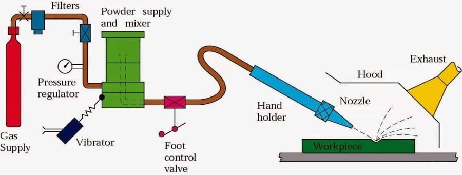
Abrasive Jet Machining is a non traditional method of removing materials by using a focused stream of abrasive grains of Al2O3 or SiC carried by high-pressure gas or air at a high velocity is made to impinge on the work surface through a nozzle of 0.3- to 0.5-mm diameter.
In other words, Abrasive jet machining is the process of impinging a high-speed stream of abrasive particles onto a work surface via a nozzle with high-pressure gas or air, and metal removal occurs due to erosion caused by high-speed abrasive particles.
The impact of the particles generates a concentrated force sufficient to perform operations such as cutting; the material is removed by the erosion of work material with abrasive grits at a speed of 150-300m/s. Abrasive grits are applied in a high-velocity gas stream.
Working Principle of Abrasive Jet Machining
The working principle of abrasive jet machining is the use of a high-speed stream of abrasive particles carried by a high-pressure gas or air on the work surface via a nozzle.
The metal is removed due to erosion caused by abrasive particles impacting the work surface at high speeds. With each impact, small bits of material are loosened, exposing a new surface to the jet.
This process is mainly employed for such machining works which are otherwise difficult, such as thin sections of hard metals and alloys, cutting of material which is sensitive of heat damage, producing intricate holes, deburring, etching, polishing etc.
Abrasive Jet Machining Parts
1. Gas Supply
In the machining system, a gas (nitrogen, CO2, or air) is supplied under a pressure of 2 to 8 kg/cm2 . Oxygen should never be used because it causes a violent chemical reaction with workpiece chips or abrasives. This abrasive and gas mixture is ejected at a high velocity of 150 to 300 m/min from a small nozzle mounted on a fixture.
2. Filter
The filter cleans the fuel supply so that dirt and other impurities do not impede the process’s progress.
3. Pressure Gauge
The pressure gauge is used to control the compressed air pressure used in abrasive jet machining. as the pressure determines the depth of cut and the amount of force required to cut
4. Mixing Chamber
Abrasive powder is fed into the mixing chamber, and the amount of abrasives can be controlled using a vibrator. So that the abrasives and gases are thoroughly mixed in the mixing chamber.
5. Nozzle
The nozzle is used to increase the velocity of the fine abrasive jet slurry at the expense of pressure, because we know that lowering the pressure causes the velocity to increase. The jet’s velocity will be between 100 and 300 meters per second.
The nozzle can be adjusted to achieve the desired angular cutting and the material can be removed by impact erosion.
Because of the high wear, the nozzle is usually made of tungsten carbide. The nozzle’s diameter is approximately 0.2-0.8mm.
The nozzle’s material should be corrosion resistant. The nozzle has a circular or rectangular cross-section, and the head can be straight or at a right angle.
6. Abrasives
In abrasive jet machining, silicon carbide and aluminum oxide glass beads are used as abrasives. The abrasives’ shapes can be regular or irregular. The abrasives range in size from 10 to 50 microns. The mass flow rate of the abrasives is between 2 and 20 grams per minute.
The choice of abrasives is determined by the MRR, the type of work material, and the level of machining accuracy required.
Aluminum oxide (Al2O3) size 12, 20, 50 microns is good for cleaning, cutting, and deburring; Dolomite size 200 mesh is used for Etching and polishing.
Sodium bicarbonate has a particle size of 27 microns and is used for cleaning, deburring, and cutting soft materials.
7. Workpiece
The metal removal rate is determined by the nozzle diameter, the composition of the abrasive gas mixture, the hardness of the abrasive particles and the hardness of the work material, particle size, jet velocity, and the distance of the workpiece from the jet. In cutting glass, a typical material removal rate for abrasive jet machining is 16 mm/min.
8. Regulator
The regulator is used for controlling the flow of compressed air flowing through the pipe.
Working of Abrasive Jet Machining
In the machining system shown in Fig, a gas (nitrogen, CO2, or air) is supplied under a pressure of 2 to 8 kg/cm2 . Oxygen should never be used because it causes a violent chemical reaction with workpiece chips or abrasives. After filtration and regulation, the gas is passed through a mixing chamber that contains abrasive particles and vibrates at 50 Hz.
From the mixing chamber, the gas, along with the entrained abrasive particles (10–40 µm), passes through a 0.45 mm diameter tungsten carbide nozzle at a speed of 150 to 300 m/s. Aluminum oxide (Al2O3) and silicon carbide powders are used for heavy cleaning, cutting, and deburring.
Magnesium carbonate is recommended for use in light cleaning and etching, while sodium bicarbonate is used for fine cleaning and the cut- ting of soft materials. Commercial-grade powders are not suitable because their sizes are not well classified. They may contain silica dust, which can be a health hazard.
It is not practical to reuse the abrasive powder because contaminations and worn grit will cause a decline of the machining rate. The abrasive powder feed rate is controlled by the amplitude of vibrations in the mixing chamber. The nozzle standoff distance is 0.81 mm. The relative motion between the workpiece and the nozzle is manually or automatically controlled using cam drives, pantographs, tracer mechanisms, or using computer control according to the cut geometry required.
Masks of copper, glass, or rubber may be used to concentrate the jet stream of abrasive particles to a confined location on the workpiece. Intricate and precise shapes can be produced by using masks with corresponding contours. Dust removal equipment is incorporated to protect the environment.
Applications of Abrasive Jet Machining
Lets discuss what is use of abrasive jet machining :
1. Drilling holes, cutting slots, cleaning hard surfaces, deburring, and polishing
2. Deburring of cross holes, slots, and threads in small precision parts that require a burr-free finish, such as hydraulic valves, aircraft fuel systems, and medical appliances.
3. Machining intricate shapes or holes in sensitive, brittle, thin, or difficult-to-machine materials
4. Insulation stripping and wire cleaning without affecting the conductor
5. Micro-deburring of hypodermic needles
6. Frosting glass and trimming of circuit boards, hybrid circuit resistors, capacitors, silicon, and gallium.
7. Removal of films and delicate cleaning of irregular surfaces because the abrasive stream is able to follow contours
8. It is used for abrading and frosting glass, ceramics, and refractories and is less expensive than etching or grinding.
9. Cleaning of metal layering, such as resistive coating.
10. Small casting deflashing and parting line trimming on injection molded parts and forgings
11. It is used to engrave registration numbers on toughened glass used in automobile windows.
12. Used to clean metallic molds and cavities.
13. Cleaning surfaces of corrosion, paints, glues, and other contaminants.
Advantages and Disadvantages of Abrasive Jet Machining
Advantages
Because AJM is a cool machining process, it is best suited for machining brittle and heat-sensitive materials like glass, quartz, sapphire, and ceramics.
The process is used for machining super alloys and refractory materials.
It is not reactive with any workpiece material.
No tool changes are required.
Intricate parts of sharp corners can be machined.
The machined materials do not experience hardening.
No initial hole is required for starting the operation as required by wire EDM.
Material utilization is high.
It can machine thin materials.
A high surface finish can be obtained through this process.
Disadvantages
1. The removal rate is slow.
2.Stray cutting can’t be avoided (low accuracy of ±0.1 mm).
3. The tapering effect may occur especially when drilling in metals.
4. The abrasive may getimpeded in the work surface.
5. Suitable dust-collecting systems should be provided.
6.Soft materials can’t be machined by the process.
7.Silica dust may be a health hazard.
8. Ordinary shop air should be filtered to remove moisture and oil.
9.Process capacity is less due to a low material removal rate.
10. While machining soft materials, abrasive becomes embedded, reducing the surface finish.
11. The tapering of the hole caused by the unavoidable variation of an abrasive jet disturbs cutting accuracy.
12. Because of stray cutting, accuracy is poor.
13. Because a dust collection system is a basic requirement for preventing atmospheric pollution and health hazards, the additional cost will be present.
14. The nozzle’s life is limited (300 hours).
15. Because the sharp edges of abrasive powders wear down and smaller particles can clog the nozzle, they cannot be reused.
16. A short standoff distance can cause nozzle damage.
17. Because of the flaring effect of the abrasive jet, the process accuracy is poor.
18. A taper will be present in deep holes.
19. AJM The process is harmful to the environment and causes pollution.
20. Abrasive particles in the air can create a hazardous environment.
Effect of Grain Size And Flow Rate of Abrasives on Material Removal Rate
At a given pressure, MRR increases with increasing abrasive flow rate and is determined by abrasive particle size.
However, after reaching the optimum value, MRR decreases as the abrasive flow rate is increased further.
This is because the mass flow rate of the gas decreases as the abrasive flow rate increases, and thus the mixing ratio increases, resulting in a decrease in material removal rate due to a decrease in available energy for erosion.
Effect of Exit Gas Velocity And Abrasive Particle Density:
The velocity of the carrier gas that transports the abrasive particles varies significantly with the density of the abrasive particles.
When the internal gas pressure is near twice the pressure at the exit of the nozzle and the abrasive particle density is zero, the exit velocity of gas can be increased to critical velocity.
Exit velocity will decrease for the same pressure condition if the density of abrasive particles is gradually increased.
It is because the kinetic energy of the gas is used to move the abrasive particles.
Effect of Mixing Ratio on Material Removal Rate:
As the abrasive’s mass flow rate increases, its velocity decreases, reducing the available energy for erosion and, ultimately, the material removal rate.
Effects of Nozzle Pressure on MRR
The abrasive flow rate can be increased by increasing the carrier gas flow rate. As the internal gas pressure rises, so does the abrasive mass flow rate, and thus the MRR.
The rate of material removal increases as the gas pressure rises. The kinetic energy of the abrasive particles is responsible for material removal during the erosion process.
Why are abrasive particles not reused in Abrasive jet machining?
Fine abrasive particles entrained in a gas stream are permitted to impact the work surface at high velocity (100–300m/s) to gradually degrade material in the abrasive jet machining (AJM) process. Impact erosion is the mechanism for material removal. The carrier gas transports eroded material in the form of solid small particles and utilized abrasive grits away from the machining zone. Because of the following two reasons, reusing these abrasive particles is not suggested.
Wear debris contaminates abrasives (removed work material).
Abrasives lose their sharp edges, reducing their cutting effectiveness.
Frequently Asked Questions
What is use of abrasive jet machining?
Common applications include cutting heat-sensitive, brittle, thin, or hard materials. It is specifically used to cut intricate shapes or form specific edge shapes.
Which gas is used in abrasive jet machining?
Abrasive jet machining creates a jet by mixing gas with abrasive particles. The gas used is known as carrier gas. Air, carbon dioxide, and nitrogen are three of the most commonly used carrier gases. Oxygen is never used as a carrier gas because it can oxidize the work piece’s surface.
AJM can be used for
Abrasive jet Machining process can be used for can be used for deburring, cutting, cleaning and for many other heavy duty applications.
In abrasive jet machining process the abrasive particles should be
In AJM, generally, the abrasive particles of around 50 μm grit size would impinge on the work material at a velocity of 200 m/s from a nozzle of I.D. of 0.5 mm with a stand-off distance of around 2 mm.
How is the material removed in Abrasive jet machining?
In abrasive jet machining, a focused stream of abrasive particles is impinged on the work surface through a nozzle and work material is removed by erosion by high velocity abrasive particles carried by high pressure air or gas. Because the carrier gas acts as a coolant, the cutting process is cool. The high-velocity abrasive stream is created by transferring the pressure energy of the carrier gas or air to its kinetic energy, resulting in a high-velocity jet.
Abrasive Jet Machining MCQ
Q. In Abrasive jet machining, work piece material of removed by which of the following means? a) Vaporization b) Electro plating c) Mechanical abrasion d) Corrosion Answer: c
Explanation: Abrasive particles hit the surface with high pressure and high velocities, which removes the material.
Q.Metal removal rate in Abrasive jet machining increases with
a) Increase in standoff distance but decreases beyond a certain limit b) Decrease in abrasive flow rate c) Decrease in grain size in grain size of abrasives d) None of the mentioned Answer: a Explanation: MRR is directly proportional to standoff distance up to certain limit. After certain limit, kinetic energy of abrasives starts decreasing.
Q. Which type of materials can be machined using Abrasive jet machining? a) Glass b) Ceramics c) Hard materials d) All of the mentioned
Answer: d Explanation: Materials like ceramics, glass, hard and super hard materials can be machined using Abrasive jet machining.
Hope you liked this article covering all the aspects of Abrasive Jet Machining covering its working principle, advantages, disadvantages and its application.
If you liked the article, please share it with your friends and give your feedback in the comment section.
In this article we will discuss about Alloy Steel, which are very commonly used in Industries as well as in da to day life. Starting with the definition we will look into its composition, types, and uses and properties.
What is Alloy Steel ?
Alloy steel may be defined as steels to which elements other than carbon are added in sufficient amounts to produce improvements in properties.
The most common alloying elements added to steel are chromium, nickel, manganese, silicon, vanadium, molybdenum, tungsten, phosphorus, copper, titanium, zirconium, cobalt, columbium, and aluminium. Each of these elements confers certain qualities upon the steels to which it is added. They may be used separately or in combination to produce desired characteristics in the steel.
Alloy steel properties : Like carbon, a number of alloying elements are soluble to produce alloys with improved strength, ductility, and toughness. Also carbon besides forming an intermetallic compound with iron, combines with many alloying elements and form alloy carbides. These alloy carbides as well as iron-alloy carbides are usually hard and lack in toughness.
Some alloying elements are added to prevent or restrict grain growth. Aluminium is considered the most effective in this respect. Others are zirconium, vanadium, chromium, and titanium. Structurally, the addition of alloying elements almost always affects the austenite-ferrite transformation mechanism by changing the temperature at which the transformation from gamma to alpha iron takes place. Some alloying elements lower and some raise the critical temperature.
The compositional and structural changes produced by alloying elements change and improve the physical, mechanical and processing properties of iron and steel. In general, alloy steels can give better strength, ductility, and toughness properties that cannot be obtained in carbon steel. Consequently, the production, design engineer should consider alloy steels in designs subject to high stresses and /or impact loading.
Almost all alloy steels are produced with fine-grained structures. Fine-grained steels have less tendency to crack during heat treatment but have better toughness and shock-resistance properties. Coarse-grained steels exhibit better machining properties and may be hardened more deeply than fine-grained steels.
Which Alloy Steel is used to make Permanent Magnet ?
1. Silicon steel
2. Vanadium steel
3. Manganese steel
4. Cobalt steel
Right answer is 4. Cobalt steel
Alnico alloy, an iron alloy with aluminum, nickel and cobalt. Alnico alloys steel used to make strong permanent magnets. They are widely used in industrial and consumer electronics.
Which Alloy Steel is used for making Precious Instruments ?
1. Silicon steel
2. Manganese steel
3. Vanadium
4. Invar steel
Right answer is 4. Invar steel
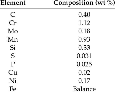
Alloy Steel Composition
Effects of Alloying Elements
In order to select the alloy steel that is best suited for a given design, the effects of primary alloying elements must be taken into account. They are :
Nickel provides toughness, corrosion resistance, and deep hardening.
Chromium improves corrosion resistance, toughness and hardenability.
Manganese deoxidizes and, contributes to strength and hardness, decreases the critical cooling rate.
Silicon deoxidizes and promotes resistance to high temperature oxidation, raises the critical temperature for heat treatment, increases the susceptibility of steel to decarburization and graphitization.
Molybdenum promotes hardenability, increases tensile and creep strength at high temperature.
Vanadium deoxidizes and promotes fine-grained structure. Copper increases resistance to corrosion and acts as strengthening agent.
Aluminium deoxidizes and, promotes fine-grained structure, and aids nitriding
Boron increases hardenability,
A summary of the effects of the chief alloying elements in steel is given in Table 4.6.
Low Alloy Steel
A low alloy steel is a metal alloy made out of steel and additional metals that have desirable qualities. About 1% to 5% of alloying elements are present in low-alloy steel. As a result, it has precise chemical compositions that provide improved mechanical qualities to resist corrosion.
During manufacture, low alloy steels are usually heat treated, normalised, and tempered. They can also be welded. Weld heat treatment, on the other hand, is required to prevent weld cracking.
Low-alloy steels provide a number of advantages over mild steel, including:
Exceptional yield strength
Capable of withstanding extreme temperatures
Good creep resistance
Resistance to oxidation
Resistance to hydrogen
Ductility at low temperatures
Alloy Steel Types or Classification of Alloy Steel
Alloy steels may be classified according to their chemical composition, structural class and purpose.
Classification According to Chemical Composition
In this aspect alloy steels are divided into Three-component steels, containing one alloying element in addition to iron and carbon : Four component steels, containing two alloying elements, etc.
Classification According to Structural Class
On the basis of the structure obtained when specimens of small cross-section are cooled in air. Alloy steels may be classified as: 1.Pearlitic 2.Martensitic 3.Austenitic 4.Ferritic and 5.Carbidic.
Classification According to Purpose
As to the uses for which their properties fit them alloy steels can be classified :
1. Structural steels 2. Tool steels 3. Steels with special physical properties.
1. Alloy Structural Steel
They are divided into three groups : low alloy (up to 5 per cent alloying elements) , medium alloy (over 5 per cent) and high alloy (more than 10 per cent). IS : 7598-1974.
Alloy structural steels are widely employed in engineering industry for parts that are subject to They have a more favourable set of mechanical properties than carbon both static and dynamic loads in operation. steels especially for articles of large cross-section. The alloying elements strengthen the ferrite, which is the chief constituent in the structure of these steels; increase the hardenability, refine the grain size; and increase the resistance to softening on heating to moderate temperatures.
The principal alloying elements in structural steels are chromium, nickel, and manganese. Tungsten, molybdenum, vanadium, and titanium are not usually employed as independent additions, They are added in conjunction with chromium, nickel and manganese.
2. Alloy Tool Steel
They are employed in tool manufacture in cases when the tool life provide by carbon steel is insufficient.
The tool industry is supplied with :
1. Low alloy steels which retain high hardness at temperatures up to 250°C.
2. Medium and high alloy steels, e.g., high speed steels which retain high hardness at temperatures up to 620°C. They acquire high cutting properties only after suitable heat treatment.
Alloy tool steels are smelted in open-hearth and electric furnaces and belong to high quality classes.
3. Alloy Steels with Special Physical Properties
They may be divided into several groups as (1) Stainless steels (2) Scale and heat Resisting steels (3) Wear Resisting steels (4) Magnet steels and (5) Steels with special thermal properties such as creep resisting steels, etc.
Special Alloy Steel
In service situations where steels must resist high temperatures, corrosion, shock, etc. special alloy steels are invaluable. The most important groups of special alloy steels are described in the following discussions.
Magnet Steels
High cobait steels, when correctly heat treated, are frequently used in the making of permanent magnets for magnetos, loud speakers and other electrical machines and instruments. Steels having compositions 15 to 40 per cent cobalt 0.4 to 10 per cent tungsten possess improved magnetic properties.
Heat Resisting Steels
Heat resisting steels are those which are particularly suitable for working at high temperatures . Such steels must resist the influences which lead to the failure of ordinary steels when put to work under high temperature. A steel controlled (developed for the stainless series) provides a useful combination of nonscaling and strength-retaining properties together with resistance to acid corrosion comparable with that of stainless steels.
Alloy steels containing 23 to 30 per cent chromium with the carbon less than 0.35 per cent are used principally for service at temperatures between 815°C and 1150°C. Furnace parts, annealing boxes and other equipments requiring resistance to high temperatures are often made of these steels.
Shock Resisting Steel
Shock resisting steels are those which resist shock and severe fatigue stresses. One grade of steel for this purpose contains 0.50 per cent carbon, 2.25 per cent tungsten, 1.50 per cent chromium and 0.25 per cent vanadium. Another grade of shock resisting steel, known as silicon manganese steels, contains 0.55 per cent carbon, 2.00 per cent silicon, 0.80 per cent manganese, and 0.30 per cent molybdenum. This kind of steel is mainly used for leaf and coil springs.
Stainless Steel
Stainless steels are essentially those containing chromium, together with other elements such as nickel, and are grouped as under.
Austenitic stainless steel. Probably the most important under this group is that containing 15 to 20 per cent chromium and 7 to 10 per cent nickel. A steel containing 18 per cent chromium and 8 per cent nickel is very widely used and is commonly referred to as 18/8 stainless steels.
Martensitic stainless steel. This group often termed plain chromium types of stainless steel, which contain 10 to 14 per cent chromium and, with the odd exception, have no other major alloying element. These steels are all hardenable by heat treatment.
Ferritic stainless steel. This group contains mainly 14 to 18 or 23 to 30 per cent chromium again with no other major alloying element. They cannot be hardened by heat treatment.
Maraging Steel
They are iron based alloys containing 18 Ni 8 Co 5 Mo with small amounts of Al and Ti and less than 0.03 per cent C. The strength is maintained with increase in section thickness and also up to 350°C, These steels are used for air frame and engine components, injection moulds and dies.
On cooling from the austenitic condition the alloy transforms to a fine lath type martensite, and precipitation hardening is induced by maraging at 480°C.
The steels have high fracture toughness due to a combination of fine grain size of the martensite and the high dislocation density, leading to fine precipitation.
High Speed Steel
High-speed steels (HSS) get their name from the fact that they may be operated as cutting tools at much higher cutting speeds than is possible with plain carbon tool steels. High-speed steels operate at cutting speed 2 to 3 times higher than for carbon steels.
When a hard material is machined at high speed with heavy cuts, sufficient heat may be developed to cause the temperature of the cutting edge to reach a red heat. This temperature would soften carbon tool steel containing even up to 1.5 per cent carbon to the extent of destroying their cutting ability. Certain highly alloyed steels, designated as high-speed steels, therefore, have been developed which must retain their cutting properties at temperatures up 600°C to 620°C.
We have tries to cover all the details of the topic Alloy Steel to a greater extent ranging from Definition, Composition, Properties, and Uses. If you like this article, please share it with your friends and give your feedback in the comment below.