Constrained Motion – Definition, Types, Examples, Images

What is Constrained Motion ?

A constrained motion is a motion of any object which occurs when an object is forced to move in a restricted way.

Or, we can say, The motion which can’t proceed arbitrarily in any manner is called constrained motion.

In simple language, It is the motion which we want to occur or Simply the required motion is called Constrained motion.

For example, suppose we want a straight line motion from a car but the car moves on curved path and we control it and forcefully moved in straight line.

The straight line motion of a car is constrained motion.

Example of Constraints motion

  • The motion of a gas molecule in a spherical container.
  • A particle moving down a rough or smooth inclined plane,
  • A particle sliding down a curve under gravity,
  • The motion of rigid body as distance between any two particles remains constant.
  • Bicycling is the best example. There the input is the couple produced due to the bicycling. The output is the rotation of a back wheel.
  • Motion of point mass of simple pendulum is constrained as it always remains at a fixed distance from point of suspension.
  • A particle tied to one end of a string and made to move in a particular way.
  • The motion of beads of an abacus is constrained in one dimension by the supporting wires.
  • Motion of a particle moving on the surface of sphere is restricted as it can move either on the surface or outside the surface of sphere.

What is Constraints ?

When an object is forced to move along a particularly given path under the action of external impressed forces. The restrictions act on the motion or position or both of a system of an objects are known as constraints. Constraints limit the motion of an object.

What is Constraints Force ?

Constraint forces are the forces that the constraining object applies to the object in order for it to follow the movement constraints. Constraint Forces are the forces that the constraining object exerts on the object to make it follow the motional constraints.

The motion of an object is limited by constraint forces. Constrained motion is defined as a speed that cannot move arbitrarily in any direction or the motion that we want to occur, or simply the required motion. For example, if we want circular motion from a fan as an output and it moves circularly, we have constrained motion.

TYPES OF CONSTRAINED MOTION

1. Completely Constrained Motion

When the motion between two elements of a pair is in a definite direction irrespective of the direction of the force applied, it is known as completely constrained motion. The constrained motion may be linear or rotary. The sliding pair of Fig. 1.3(a) and the turning pair of Fig. 1.3(b) are the examples of the completely constrained motion. In sliding pair, the inner prism can only slide inside the hollow prism. In case of a turning pair, the inner shaft applied in a can have only rotary motion due to collars at the ends. In each case the force has to particular direction for the required motion.

For example :- In a steam engine, the piston and cylinder form a pair, and the piston’s motion is limited to a specific direction, i.e., it will only reciprocate relative to the cylinder regardless of the direction of the crank.

Some more examples :-

  • The motion of a square bar in a square hole
  • The motion of a shaft with a collar at each end in a circular hole.

2. Incompletely Constrained Motion

When the motion between two elements of a pair is possible in more than one direction and depends upon the direction of the force applied, it is known as incompletely constrained motion. For example, if the turning pair of Fig. 1.4 does not have collars, the inner shaft may have sliding or rotary motion depending upon the direction of the force applied. Each motion is independent of the other.

For example :- A circular strip or shaft in a circular hole is an example of an incomplete constrained motion because it can rotate or slide in the hole. Both motions are unrelated.

3. Successfully Constrained Motion

When the motion between two elements of a pair is possible in more than one direction but is made to have motion only in one direction by using some external means, it is a successfully constrained motion.

For Footstep bearing example, a shaft in a footstep bearing may have vertical motion apart from rotary motion (Fig. 1.5). But due to load applied on the shaft it is constrained to move in Mechanisms and Machines that direction and thus is a successfully constrained motion.

Similarly, a piston in a cylinder of an internal combustion engine is made to have only reciprocating motion and no rotary motion due to constrain of the piston pin. Also, the valve of an IC engine is kept on the seat by the force of a spring and thus has successfully constrained motion.

For example :- motion of shaft

When a compressive load is applied to the shaft, the motion of the shaft in a footstep bearing is successfully constrained. The shaft can move upward or rotate in a bearing. This is an example of a motion that is only partially constrained. When a load is applied to the shaft, however, it is prevented from moving axially upward. Successfully constrained motion refers to the movement of two people.

Some more examples :-

  • The motion of an I.C. engine valve, these are kept on their seat by a spring
  • The piston reciprocating inside an engine cylinder
  • Shaft in a footstep bearing

Frequently Asked questions ( FAQ )

What is Constrained Motion ?

Constrained motion are motion which occurs when an object is forced to move in a specific manner. It may have to move along a curved track, slide on a table that may accelerate upwards, maintain contact with an accelerating wedge, and so on.

What is successfully Constrained Motion ?

When the motion between the elements forming a pair is such that the constrained motion is completed by some other means rather than by itself, the motion is said to be successfully constrained.

What is completely Constrained Motion ?

When a pair’s motion is limited to a definite direction regardless of the direction of force applied, the motion is said to be completely constrained.

What is incompletely Constrained Motion ?

When a pair’s motion can occur in more than one direction. It is referred to as “incompletely constrained motions.” A change in the direction of the affected force can change the direction of relative motion between the pair.

What is the difference between Constrained and Unconstrained?

Unconstrained simply means that the choice variable can take on any value—there are no restrictions. Constrained means that the choice variable can only take on certain values within a larger range.

These were the details of Constrained Motion and its types. We also covered the definitions of various terms associated with it. Hope you like the article. Please give your feedback in the comment below.

Check Out Other Important Topics

Foundry Tools And Equipment – List, Names & Images

Sand Testing Methods – Full Process

Types of Casting Defects – Complete Overview

Moulding Sand – Properties, Types, Process, MCQs

Plant Layout – Types, Objectives, Principles, Advantages

IC EngineImportant PDFsBoilersSynergy Maritime ExamNaval ArchMEO Class 4
Interview QuestionsDifference BetweenTypes of PumpsAuxiliary MachinesTypes of ValvesHome

Foundry Tools And Equipment – List, Names & Images

Foundry tools and equipment may be classified into three groups, namely, hand tools, flasks, and mechanical tools.

1. Hand Tools

Hand Tools :- The hand tools uses are fairly numerous. A brief description of the most important tools is given here.

1. Shovel

A shovel mixing and tempering moving the sand from.

2. Riddle

A riddle, consists of a circular or fitted with a standard shown in Fig. 11.34. It is materials such as nails, wood, etc., from the moulding sand. Both hand and power riddles are available, the latter being used where large volumes of sand are to be riddled.

3. Sprue pin

Sprue foundry tools are a tapered (Fig. 11.35) pushed through the cope to the joint of the mould. As the peg is withdrawn it removes the sand, leaving an opening for the metal. This opening is called the sprue through which the metal is poured. The sprue pin forms the riser pin.

4. Bellow

Bellows are used to blow loose particles of sand from the pattern and the mould cavity. A hand blower is shown in Fig. 11.36.

Moulding machines are also provided with a compressed air jet to perform this operation.

5. Rammer

Hand rammer (Fig. 11.37) foundry tools are a wooden tool used for packing or ramming the sand into the mould. One end, called the peen, is wedge shaped, and the opposite end, called the butt, has a flat surface. Floor rammers are similar in construction but have long handles. Pneumatic rammers are used in large moulds saving considerable labour and time.

6. Trowel

A trowel consists of a metal blade fitted with a wooden handle (Fig. 11.38). Trowels are employed in order to smooth or sleek over the surfaces of moulds. A moulder also uses them in repairing the damaged portions of a mould. The usual trowel is rectangular in shape and has either a round or square end.

7. Slick

It is a small double-ended tool having a flat on one end and a spoon on the other end (Fig. 11.39). This tool is also made in a variety of shapes. The type most commonly used is the oval spoon. Slicks are used for repairing and finishing small surfaces of the mould.

8. Lifter

Lifters are made of thin sections of steel of various widths and lengths with one end bent at right angles as shown in Fig. 11.40. They are used to clean and finish the bottom and sides of deep, narrow openings in moulds.

9. Strike-off bar

The strike-off bar is a piece of metal or wood with a straight edge (Fig. 11.41). It is used to strickle or strike-off excess sand from the mould after ramming to provide a level surface.

10. Swab

A simple swab is a small brush foundry tools having long hemp fibers. A bulb swab has a rubber bulb to hold the water and a soft hair brush at the open end. A bulb swab is shown in Fig. 11.42. Swabs are used for moistening the sand around a pattern or for applying paint.

11. Gate Cutter

It is a small piece of tin plate shaped as shown in the figure. This serves as a tool for cutting gates and runners in the mould.

12. Mallet

A raw hide mallet is used to loosen the pattern in the mould so that it can be withdrawn without damage to the mould.

13. Vent rod

A vent rod or wire, as shown in Fig. 11.45, is used to make a series of small holes to permit gases to escape while the molten metal is being poured.

14. Draw spike or screw

The draw spike is a pointed steel rod, with a loop at one end. These foundry tools are used to rap and draw patterns from the sand. Fig. 11.46 illustrates two kinds of draw spikes. The draw spike is threaded on the end to engage metal patterns.

15. Rapping plate

A rapping or lifting plate, as shown in Fig. 11.47, is used to facilitate rapping and lifting of the pattern from the mould. The plate must be firmly attached to the pattern by long screws or even bolts in larger patterns. The moulder places a draw spike in the rapping hole and raps it to loosen the pattern, then fixes draw screws into the screw hole on the plate.

16. Pouring weight

A pouring weight is simply a plate of cast iron with a cross-shaped opening cast in it to give considerable liberty in placing the runner in the mould. It is used on the top of a mould for giving a weight to prevent the pressure of the liquid metal from forcing the mould apart causing a run-out.

17. Gaggers

Gaggers, sometimes called lifters, are iron rods bent at one end or both ends (Fig. 11.48). They are used for reinforcement of sand in the top part of a moulding box, and to support hanging bodies of sand.

18. Clamps

Clamps (Fig. 11.49) are foundry tools used for holding together the cope and drag of the completed mould to prevent he cope from floating or rising when the metal is introduced into the mould.

19. Spirit level

The spirit level in Fig. 11.50 is used by the moulder to ensure that his bed of sand moulding box or moulding machine table is horizontal

20. Moulding board and bottom board

A moulding board is a smooth wooden board on which the flask and patterns are placed when the mould is started. When the mould is turned over, the function of this board is ended the mould is placed on a similar board, called a bottom board, which acts as a support for the mould until it is poured.

2. Moulding Boxes

Another group of foundry tools are Moulding Boxes. Sand moulds are prepared in specially constructed boxes called flasks. The purpose of the flask is to impart the necessary rigidity and strength to the sand in moulding. They are usually made in two parts, held in alignment by dowel pins. The top part is called the cope and the lower part the drag.

If the flask is made in three sections, the centre is called the cheek (Fig. 11.3). These flasks can be made of either wood or metals depending upon the size required and the purpose the flasks must serve. Metal flasks are used when production is large, but when only a few castings are needed and a special flask must be obtained, the wooden flask is the most economical.

Two types of flasks are used in a foundry: (1) the snap flask, and (2) the tight or box flask. A snap flask (Fig. 11.51) is made with the hinge on one corner and a lock on the opposite corner so that the flask may be removed from the mould before it is poured. The snap flask is of advantage in that many moulds can be made for the same pouring from a single flask.

The tapered slip flask is another type of removal flask. It has rigid corners but the sides have a smooth inside surface and a 5-degree taper to allow the flask to be removed upward.

A box flask shown in Fig. 11.52 must remain in the mould until the pouring operation is completed. These boxes are usually made of metal and are very suitable for small and medium sized moulding.

A typical wooden moulding box is shown in Fig. 11.53. The side timbers are continued beyond the ends of the box to form two handles at each end. The sides are held together by strong cross timbers, reinforced with bolts. This is easier to handle and may be employed for large moulding.

3. Mechanical Tools

The third group of foundry tools are Mechanical Tools. The mechanical tools in the foundry include the many types of moulding machines that will ram the mould, roll it over, and draw the pattern. Besides, there are power operated riddles, sand mixers, sand conveyors, etc.

The mould is even poured and shaken out mechanically, and the casting is taken by machine to the cleaning department. The amount of mechanisation, however, varies considerably from one foundry to the other. Mass-production foundries making large quantities of relatively few types of castings are in a position to mechanise more completely than the job-shop foundries.

These were list of different types of foundry tools and equipment. Their work has also been mentioned. Hope you enjoyed the article. Gives your feedback in the comment section.

Check Out Other Important Topics

Plant Layout – Types, Objectives, Principles, Advantages

Types of Punches – Uses, Working, Applications, Pictures

Types of Dies – Classification, Uses, Pictures

Types of Rivets – Working & Their Uses [with Images]

Types of Fasteners – Uses & Examples [with Pictures]

Foundry Tools And Equipment – List, Names & Images

IC EngineImportant PDFsBoilersSynergy Maritime ExamNaval ArchMEO Class 4
Interview QuestionsDifference BetweenTypes of PumpsAuxiliary MachinesTypes of ValvesHome

Group Technology (GT) – Definition, Layout, Benefits

The article covers What is group technology, Layout, benefits, advantages and disadvantages.

What is Group Technology ?

Group technology, or GT, is a manufacturing technique in which parts with similar geometry, manufacturing process, and/or functions are manufactured in a single location using a small number of machines or processes. It is based on the general principle that many problems are similar, and that by grouping similar problems, a single solution to a set of problems can be found, saving time and effort.

Define Group Technology

Group technology is an important technique in the planning of manufacture that allows the advantages of product line organization to be obtained in what otherwise would be jobbing or batch manufacture. This technique identifies the sameness of parts, equipment or processes. Machines are grouped according to the routing required for a
family of parts rather than by their functions.

By using this technique, production planning and control functions are also simplified as the group of machines can be treated as one work center, thereby decreasing the number of work centers and simplifying the routing of parts. Waiting time is reduced significantly and work center utilization in improved.

It offers its greatest benefits when it is extended to all phases of production and production preparation including drafting and part programming for NC machine.

Group Technology Layout

One of the most popular types of hybrid layouts is group technology (GT) or cell layouts. It has the advantage of bringing the efficiencies of a product layout to a process layout environment. Group technology is the process of creating groupings of products based on similar processing requirements.

Group Technology

Objectives of Group Technology

  1. Reduce average lot size
  2. Increase part variety
  3. Increase variety of materials
  4. Achieve close tolerance
  5. Improve scheduling
  6. Reduce tooling
  7. Increase equipment utilization

Advantages of Group Technology

The generally accepted benefits of group technology are :

  1. Reduction in setting up times and cost.
  2. Reduction in material handling costs.
  3. Reduction in inventory cost and thus reduction of lot size.
  4. Reduction in throughput time.
  5. Reduction in work-in-progress.
  6. Reduction in planning cost and simplifying the documentation and administration of the process planning function.
  7. Simplified estimating, accounting and work man­agement.
  8. Output is improved due to improved resource utili­zation.
  9. Improved quality and less scrap.
  10. Smaller variety of tools, jigs and fixtures.
  11. Better space utilization
  12. Robots can be easily used for material handling.

This technique, along with good general management practices, therefore has a large contribution towards improving productivity in general and reducing inventory cost in particular.

Disadvantages of Group Technology

  1. The Additional cost of implementation of this system.
  2. The rate of change in product range and mix.
  3. Difficulties with out-of-cell operations.
  4. Coexistence with non-cellular systems.
  5. Involves less manufacturing flexibility.
  6. Increases the machine down time as machines are grouped as cells which may not be functional throughout the production process.

Uses of Group Technology

A classification system can be used to easily follow a GT technique. There are numerous parts in any assembly. These various parts can be classified into three broad categories, namely

1. Standard and proprietary parts (like nuts, bolts, screws, keys, washers, etc.)

2. Similar parts (like shafts, gears, bearings, levers, etc.)

3. Product specific parts (like gear box, bed, saddle, etc.)

It should be noted that the group technology is not concerned with categories I and (iii), but rather with category (ii). The goal is to group the range of parts under category (ii) in some way for manufacturing purposes.

Several classification systems have been developed, and one must carefully consider the system based on his needs. A company with a wide range of products requires a complex detailed system, but the same is not true for one with a limited range. Provision should always be made for future likely growth, and the classification system chosen should keep this requirement in mind.

Hope you enjoyed reading this article about the Group Technology. You can give your feedbacks in the comment below.

Check Out Other Important Topics

Plant Layout – Types, Objectives, Principles, Advantages

Types of Punches – Uses, Working, Applications, Pictures

Types of Dies – Classification, Uses, Pictures

Types of Rivets – Working & Their Uses [with Images]

Types of Fasteners – Uses & Examples [with Pictures]

IC EngineImportant PDFsBoilersSynergy Maritime ExamNaval ArchMEO Class 4
Interview QuestionsDifference BetweenTypes of PumpsAuxiliary MachinesTypes of ValvesHome

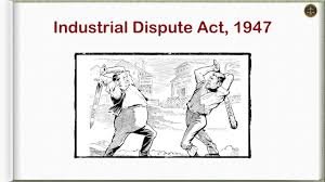
Industrial Disputes Act 1947 – Objectives, Purpose, Pdf, Notes

In this article we will discuss about the Industrial Dispute Act 1947, it’s provisions and details of enactment. At the end you can download pdf as a note given as Industrial Disputes Act 1947 pdf.

The Industrial Disputes Act 1947 is applicable in whole of India. This Act is a replacement of Trade Disputes Act of 1929. The Trade Disputes Act imposed certain restraints on the right of strike and lockout in public utility Services but lacks any provision for the settlement of Industrial Disputes, either by reference to a Board of Conciliation or to a Court of Inquiry. In order to remove this deficiency, the Industrial Disputes Act 1947 was passed.

This act is the main legislation for investigation and settlement of all industrial disputes. The Act enumerates the contingencies when a strike or lock-out can be lawfully resorted to, when they can be declared illegal or unlawful, conditions for laying off, retrenching, discharging or dismissing a workman, circumstances under which an industrial unit can be closed down and several other matters related to industrial employees and employers.

What is Industrial Dispute Act 1947 ?

Industrial Disputes Act 1947 is an act to make provision for the investigation and settlement of industrial disputes, and for certain other purposes.
And it is expedient to make provision for the investigation and settlement of industrial disputes, and for certain other purposes hereinafter appearing.

When it came under force ?

Enacted on 11 March 1947 and It came into force on 1 April 1947. It was replaced by the Industrial Relations Code, 2020.

Industrial Disputes Act Definition

The Industrial Disputes Act defines “Industrial dispute” as a dispute or difference between workmen and employers or between workmen and workmen, which is connected with employment or non-employment or the terms of employment or with the conditions of labour.

Purpose of Industrial Dispute Act

The main purpose of the Industrial Disputes Act 1947 is to ensure fair terms between employers and employees, workmen and workmen as well as workmen and employers..

The objective of the Industrial Disputes Act is to secure industrial peace and harmony by providing machinery and procedure for the investigation and settlement of industrial disputes by negotiations. An Act to make provision for the investigation and settlement of industrial disputes, and for certain other purposes.

Objectives of Industrial Disputes Act 1947

The basic objectives of the Industrial Dispute Act 1947 are :-

  1. To provide a suitable machinery for the just, equitable and peaceful settlement of industrial disputes.
  2. To promote measures for securing and preserving unity and good relations between employers and employees.
  3. To remove illegal strikes and lockouts.
  4. To provide relief to workers against layoffs, retrenchment, wrongful dismissal and victimization.
  5. To promote Collective bargaining.
  6. To ameliorate the conditions of workers.
  7. To avoid unfair labour practices.

The objective of the Industrial Disputes Act 1947 is to secure industrial peace and harmony by providing machinery and procedure for the investigation and settlement of industrial disputes by negotiations. An Act to make provision for the investigation and settlement of industrial disputes, and for certain other purposes.

Who does the Industrial Disputes Act apply to?

The Industrial Disputes Act extends to whole of India and applies to every Industry and its various industrial establishment carrying on any business, trade, manufacture or distribution of goods and services irrespective of the number of workmen employed there in.

Who of the following is not included as a Workman under the Industrial Dispute Act?


Thus, it can be said that an employee is not a workman and is not included with the ambit of Industrial Dispute Act 1947, when,
· The person is not employed in an industry,
· His work is to hire or reward and is free of charge,
· He is not employed to do the type of work specified in the definition,
· There is no contractual relationship of master and servant. Such relationship exist when the workman is under supervision, direction and control of the master.
· A person employed in a supervisory work and drawing wages in excess of Rs. 1600/- p.m.
· He is within the specific category of employees as mentioned in section 2(s) of the Act.

Which is not considered as an Industrial Dispute?

The Supreme Court and majority of Industrial Tribunals held that, a dispute raised by a dismissed employee would not be treated as an industrial dispute, unless it is supported by a trade union or by a body or Section of workman.

What is the monthly salary limit under the Industrial Dispute Act 1947?

The Bill amends the Industrial Disputes Act 1947. The Act provides for settlement of disputes between workers and management. The Act currently does not apply to persons who are employed in a supervisory capacity and who earn more than Rs 1,600 per month. The Bill raises this ceiling to Rs 10,000 per month.

What is Industrial Dispute how does it differ from an Individual Dispute?

Difference between the industrial dispute from the individual dispute. The industrial dispute conveys the meaning that the dispute must be such as would affect large groups of workmen and employers ranged in opposite sides. Whereas, the individual dispute is the one which is raised by a single worker.

How many sections are in the Industrial Dispute Act?

Fourty (40 )

Main provisions of Industrial Dispute Act

1. To encourage good relations between labor and industries, and provide a medium of settling disputes through adjudicator authorities.
2. To provide a committee for dispute settlement between industry and labor with the right of representation by a registered trade union or by an association of employers.
3. Prevent unauthorized strikes and lockouts.
4. Reach out to labor that has been laid-off, unrightfully dismissed, etc.
5. Provide labor the right to collective bargaining and promote conciliation.

Industrial Dispute Act 1947 Pdf / Notes

If you want to download the Industrial Dispute Act 1947 Pdf or Notes, link is given below.

There are two pdf available here.

Industrial Dispute Act 1947 Pdf

1. Download link — Click

2. Download link — Click

Check Out Other Important Topics

IC EngineImportant PDFsBoilersSynergy Maritime ExamNaval ArchMEO Class 4
Interview QuestionsDifference BetweenTypes of PumpsAuxiliary MachinesTypes of ValvesHome

Manufacturing Processes – Definition, Types, Examples

What is manufacturing process ?

A Manufacturing process is the production of workpieces having defined geometric shapes. It is one of the most important production technologies. Other technologies are process technology (production of chemicals etc.) and energy technology (production of electricity etc. ).

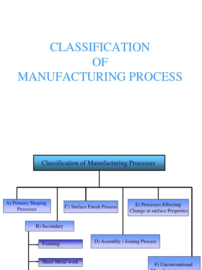
Classification of Manufacturing Process

Manufacturing processes can be classified in six groups, they are following :-

Manufacturing Process

1. Primary Shaping Processes

Primary shaping or forming is manufacturing of solid body from a molten or gaseous state or from an Amorphous material.

Amorphous materials are gases, liquid, powders, fibers, chips. A primary shaping or forming tool contains a hollow space which, with the allowance for contraction usually corresponds to the form of the product. Some of the important priming shaping processes are ;

  1. Casting
  2. Powder metallurgy
  3. Plastic technology

2. Deforming Process

Deforming processes is manufacturing process which make use of suitable stresses like compression, tension, shear or combined stresses to cause plastic deformation of the materials to produce required shapes without changing its mass or material composition. In forming, no material is removed; they are deformed and displaced. Some of the forming processes are ;

  1. Forging
  2. Extrusion
  3. Rolling
  4. Sheet metal working
  5. Rotary swaging
  6. Thread rolling
  7. Explosive forming
  8. Electromagnetic forming

3. Machining/removing Processes

The principle used in all machining process to generate the surface required by providing suitable relative motion between the workpiece and the tool. In these processes material is removed from the unwanted regions of the input materials. In this ,the work material is subjected to a lower stress as compared to forming processes. Some of the machining processes are ;

  1. Turning
  2. Drilling
  3. Milling
  4. CP and planing
  5. Grinding
  6. EDM
  7. ECM
  8. Ultrasonic machining

4. Joining processes ( Types of manufacturing process )

In this process two or more pieces of metal parts are united together to make sub-assembly or final product. The joining process can be carried out by fusing pressing, rubbing, riveting or any other means of assembling.

Some of the important joining processes are are;

  1. Pressure welding
  2. Resistance welding
  3. Diffusion welding
  4. Explosive welding
  5. Brazing
  6. Soldering

5. Surface finishing processes

These processes are utilized to provide intended surface finish on the metal surface of a job. By Imparting a surface finishing process, dimension of the part is not changed functionally ; either a very negligible amount of metal is removed from or certain material is added to the surface of the job. Surface cleaning process is also accepted as a surface finishing process, Some of the surface finishing processes are :

  1. Plastic coating
  2. Metallic coating
  3. Organic finishes
  4. Inorganic finishes
  5. Anodizing
  6. Buffing
  7. Honing
  8. Tumbling
  9. Electro- plating
  10. Lapping
  11. Sanding

6. Material Properties Modification Process

In this type of manufacturing process, material properties of a workpiece is changed in order to achieve desirable characteristics without changing the shape. Many structural metals undergo some special treatment to modify their properties so that they will perform better for their intended use. Some of the properties are:

  1. Heat and surface treatment
  2. Annealing
  3. Surface relieving. etc..

In this article we learnt about Different types of manufacturing process along with their properties and processes involved.

Check Out Other Important Topics

IC Engine

Electrical

Important PDFs

Boilers

Synergy Maritime Exam

Naval Arch

Interview Questions

Difference Between

Types of Pumps

Types of Valves

MEO Class 4

Auxiliary Machines

Home

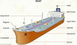
Bulwark on a Ship: Definition, Height, Constructions

Bulwark on a Ship

Bulwark on a ship

What is a Bulwark on a Ship ? Bulwark Definition

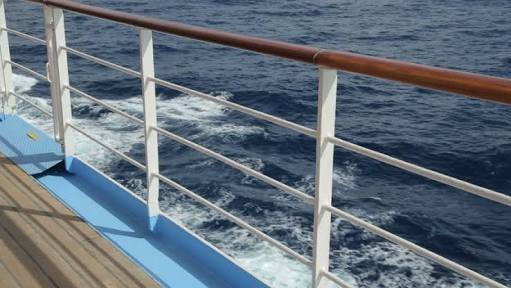
Bulwark on a ship is a nautical term for a ship’s side to be extended above the level of a weather deck.

Define Bulwark

It is a Vertical Fore-and-aft plating just above the upper edge of the side of the ship surrounding the exposed deck(s).

Bulwark ship meaning : It is defined as boundary designed on the ship’s side to prevent passengers and crew from falling to sea.

As protection for crew and passengers, bulwarks fitted on weather decks and it is not intended as a major structural function.

Bulwark Definition : In simple sentence, bulwark meaning , a solid wall like structure fitted on the ship’s side above the upper deck to protect crew member falling into the sea.

As we know that it is fitted only to save falling crew and not intended as major structure so, they are of light scantling. The high stresses connected to adjacent structure is avoided.

Also read :- Difference between 2 stroke and 4 stroke engine

Freeing ports

Freeing ports are the opening provided on the ship side to allow the free passing of water on the deck to the sea freely.

Or,

It is an Opening or hole in the bulwarks at the level of the deck to drain water from the deck.

Bulwark on a ship

As we see the figure of Bulwark ,it is open.

Why it is open ?

The opening is called freeing ports.

Freeing ports are cut into bulwarks forming wells on decks so that the water can drain quickly.

Freeing ports area on each side depend on the length of well deck.

The ports’ lower edge must be as close to the deck as possible. It is appropriate to fit bars spaced about 230 mm apart across the port. Where hinge flaps are fitted and these hinges should be non-corrodible.

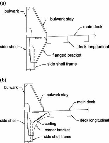
Structure of the Bulwark on a ship

What is the height of Bulwark ?

The height of Bulwark is at least 1 metre high on the exposed freeboard and the superstructure deck.

However, a reduced height may be allowed if this interferes with the operation of the ship.

Range of height

In open position,the height should be 1 metre high.These are supported by stanchions.

In some ships,these must not be more than 1.2 metres apart for forward 7 percent (%) of the length of the ships otherwise,it not be more than 1.83 metres.

Construction of the Bulwark on a ship

Bulwark should not be welded to the sheer strake to the half length amidship as this is liable to cause the plating to crack.

This can be done by riveting the bulwark to the sheer strake or by using FLOATING BULWARK, which has the advantages that the space/gap between it and the edge of the deck serve as a freeing port.

It is normally founded in a rounded sheer strake.

More photos

1.

Bulwark of ship

2.

Bulwark on a ship

So with this article we understand bulwark meaning along with more than one bulwark definition. Bulwark on a ship is very important from safety point of view.

What is camber of a ship?

In naval architecture, camber is a measure of lateral main deck curvature. The curve is applied transversely to a deck and is measured as the height of the deck at the centerline above the height of the deck at the side.

What is a girder on a ship?

A girder is a longitudinal member used in the construction of a ship’s bottom. They can be solid or hollow, and they can be placed above the keel (centre girder) or equally spaced from it (side girders). They can be continuous or divided into sections by floor sections (intercostal side girders).

What is ship gangway?

A gangway is a narrow walkway or platform that allows people to safely board a ship, truck, or train. Gangways are typically used for two purposes: allowing people and/or cargo to travel to and from docks, moored marine vessels, or aircraft, or for maintenance and loading/unloading of land-based trucks and trains.

What is the function of bulwark?

It is defined as boundary designed on the ship’s side to prevent passengers and crew from falling to sea. As protection for crew and passengers, bulwarks fitted on weather decks and it is not intended as a major structural function.

Where is bulwark located?

The Bulwark, located on the border of Tirisfal Glades and the Western Plaguelands, is the Forsaken’s last line of defence against the forces of the Scourge to the east.

What is ship keel?

The main structural member and backbone of a ship or boat, running longitudinally along the bottom of the hull from stem to stern in shipbuilding. It could be made of wood, metal, or another strong and stiff material.

What is camber and sheer?

Camber:-The deck’s transverse curvature from the centerline to the sides. This camber is used on exposed decks to direct water to the ship’s sides.
Sheer: The fore and aft curvature of the deck, rising from midship to the maximum at the ends.

What is strake in ship?

A strake is a longitudinal course of planking or plating on a vessel’s hull that runs from the boat’s stempost (at the bows) to the sternpost or transom (at the rear). The garboard strakes are the two on each side immediately adjacent to the keel.

Follow me on Twitter

Check Out Other Important Topics

IC EngineImportant PDFsBoilersSynergy Maritime ExamNaval ArchMEO Class 4
Interview QuestionsDifference BetweenTypes of PumpsAuxiliary MachinesTypes of ValvesHome

Windlass safety devices

What are windlass Safety Devices ?

Windlass Safety devices are :-

  • Overload trip
  • Emergency stop
  • Mechanical break
  • Over speed trip
  • Slipping clutch for overload,for preventing any undesirable damage such as hull damage due to anchor and rope brake out.

Check Out Other Important Topics

Home

IC Engine

Electrical

Important PDFs

Boilers

Synergy Maritime Exam

Naval Arch

Interview Questions

Difference Between

Types of Pumps

Types of Valves

MEO Class 4

Auxiliary Machines

Why discharge valve closed during starting of centrifugal pump ?

In this Article, I have Explained Why discharge valve closed during starting of centrifugal pump ? Or Why centrifugal pump started with closed discharge valve ?

Why centrifugal pump started with closed discharge valve ?

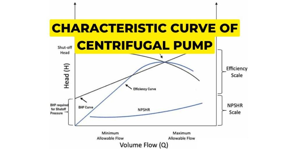
Let Us First Understand through Characteristics Curve of Centrifugal Pump. A centrifugal pumps usually started with discharge valves shut.

Considering the properties of centrifugal pump by operating characteristic curve it is clearly found that; when the amount of water delivered is zero, the power available is at minimum.

So discharge valves valve remains shut off throughout the beginning to take care of low power demand by the pump on its motor having low power output at the beginning.

This helps stabilizing pumps at the starting. When the pump is stable the discharge valves opened and high power avaibility meets the high power demand; which might be not possible for the motor to fulfill for the starting 4-5 seconds.

Why discharge valve closed during starting of centrifugal pump ?

Or,

It is a very common practice to start large capacity centrifugal pump with the closed discharge valve .

If the characteristic curve for a centrifugal pump are examined it will be seen that when the quantity of water discharged is zero the power required by the pump is zero or very small amount.

by starting the pump with discharge valve closed the power demand made by the pump on the pump motor is kept to very minimum after the pump has started and the momentary high motor current demand has stabilized the discharge valve is opened.

Why centrifugal pump started with closed Discharge valve

By closing the discharge valve, the starting current can be reduced.

As we know, at the start of any motor, the current will be high. When we start the pump with an open discharge valve, the discharge head will act on the pump, i.e. more resistance, so that the motor has to give more starting torque to the pump, which means more current is drawn by the motor.

If we start the pump with discharge valve closed, it means there no discharge head and minimum resistance to the pump and so current drawn is minimum. Although the current taken during startup of motor is more than normal, but by closing the  discharge valve of centrifugal pump we can avoid extra load act on the pump.

If there is  a check valve, then the discharge valve can be opened. Without having a check valve, we need to have the discharge valve closed if there is pressure on the discharge side of centrifugal pump  at the time of startup.

If we think differently,If there is a pressure on the pump’s discharge side,before starting it may flow back through the pump,causing a backward spin and can draw more current , resulting damage to the pump.Thus can be prevented by keeping the discharge valve of centrifugal pump closed when starting.

Check Out Other Important Topics

Home

IC Engine

Electrical

Important PDFs

Boilers

Synergy Maritime Exam

Naval Arch

Interview Questions

Difference Between

Types of Pumps

Types of Valves

MEO Class 4

Auxiliary Machines

What is difference between hyper mist and sprinkler system?

What is difference between hyper mist and sprinkler system?

Hyper mist :-

  • It use fresh water
  • It activate when two different detectors activated.
  • Pressure required for hyper mist is more as compare to sprinkler system.
  • Droplet size of hyper mist is small

Sprinkler System :-

  • It uses Sea water
  • Sprinkler has Temperature bulb
  • Pressure Required for sprinkler system is less as compare to hyper mist.
  • Droplet size of sprinkler system is bigger than hyper mist.

Check Out Other Important Topics

Home

IC Engine

Electrical

Important PDFs

Boilers

Synergy Maritime Exam

Naval Arch

Interview Questions

Difference Between

Types of Pumps

Types of Valves

MEO Class 4

Auxiliary Machines

What is Angle of Contraflexure?

In this Article,we will learn What is the Angle of Contraflexure ?

What is angle of Contraflexure ?

This is the angle at which the curve goes / moves from concave to convex.

Angle of Contraflexure
Fig.1

Or

It is the angle of heel up to which the rate of righting lever ( GZ ) With the heel is changes I.e Before this point rate of righting lever with heel is increasing but after this point rate of righting lever will decrease.

Must Read:- How does a ship move

What is it’s significance ?

The physical Significance of this point is that ,it is the point or angle at which Deck just touches the surface of sea.

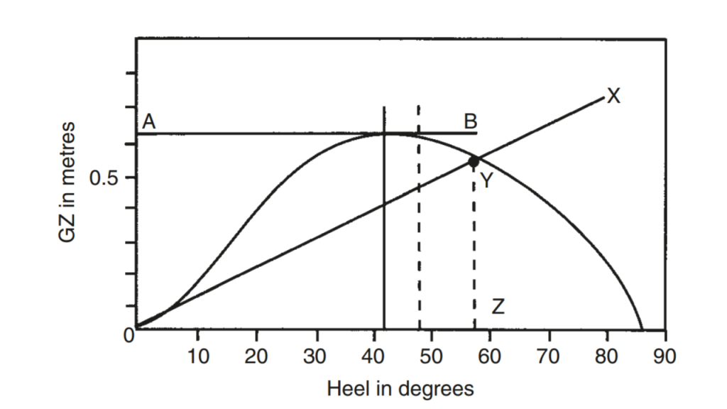
The below figure is the Curve of Statical stability for a ship in Particular condition of loading.

Angle of Contraflexure
Fig.2

How this Curve Obtained ?

This curve is obtained by plotting the Righting Lever against the angle of the heel.

Angle of Contraflexure
Fig.3

The above curve is for Positive Metacentric Height

Angle of Contraflexure
Fig.4

The above curve is for negative Metacentric Height.

From the above figure we can get following information:-

  1. Range of Stability :-The range in which the ship has positive Righting lever (GZ ) i.e 0 – 86 in figure 3. & 18- 9 in figure 4.
  2. Angle of vanishing stability:-It is the angle of heel when the righting lever (GZ ) returns to zero,or the angle at which the sign of righting lever changes from positive to Negative I.e 86 degree in the figure 3.
  3. Maximum GZ :-It is obtained by plotting a tangent to the highest point of the Curve. i.e 0.63 meters which occurs at 42 degree.
  4. Initial GM :-It is found by Drawing a tangent to the curve through the origin and then erecting a perpendicular through the angle of her log 57.3 degree.The two lines are allowed to intersect and the value of GZ is noted which is initial GM.
  5. Point of Inflection/Contraflexture :-It is the angle at which the curve goes / moves from concave to convex.

The above figure is for Negative Metacentric Height.

In the above figure,we can see that ,at an angle less than 18° the the righting arm / lever are negative and beyond 18° to 90° the righting lever is positive.

Hence, 18 degree is the angle of look or point of loll.

Note :- Initial GM of ship is plotted at 57.3°.

Now the Question come in mind that why we take Initial GM of ship at 57.3° ?

The answer of this Question is that 57.3 °= 180÷ 3.14 57.3°.


Check Out Other Important Topics

Home

IC Engine

Electrical

Important PDFs

Boilers

Synergy Maritime Exam

Naval Arch

Interview Questions

Difference Between

Types of Pumps

Types of Valves

MEO Class 4

Auxiliary Machines

Ship stability wikipedia