What is Safety Device ?
Electrical Safety Devices
Dead front type switchboard, Fuses, Relays, Circuit breakers, Earth fault indicators, Under voltage relay, Reverse power trip, Preferential trip, Over current trip, Short circuit trip, Arc chute, Ebonite Rod ( to remove static charge).
Main Engine Safety Devices
General Safety Devices :-
Insulated hand gloves, dry boiler suits, shoes without metallic part, Rubber pad in front of switchboard, 0.6m gap behind switchboard, Panel doors to be earthed, interlocked handles for opening doors.
No water, oil, or steam pipeline in its vicinity.
Overhead crane safeties
1) The most important safety feature of the crane is the electromagnetic fail safe brakes which do notallow the crane to fall with the load even when there is failure of power. For this:·
Normally centrifugal brakes are used which are fitted inside the rotating drum.·
The brake pads are always in applied state and pushed by magnetic springs when not in operation or when there is a power failure.·
As the crane is operated or the power is supplied, the spring gets pulled inward or compressed due to the electromagnetic effect of the current. This allows the crane to be operated normally.
2) Emergency stop is provided in the remote so that the operator can stop the crane at any time.
3) The motor is fitted with distance limit switch in both transverse and longitudinal direction.
4) Mechanical stoppers are provided for both directions in case the electrical distance limit trips fail.
5) The up and down travel of the hook is also attaches with automatic stopper to avoid overloading of the motor.
6) The motor is fitted with thermal protection trip. When the motor windings get overheated, trip will activate saving the motor winding from burning.
7) Load limit switch is also fitted which will trip the motor if the load to be lifted is above the crane capacity.
8) It’s the responsibility of senior officers to operate the crane and to make sure all the personnel involve in any lifting operation are at a safe distance during operation of the crane.
9) Additional tools like i-bolts, shackle, wire sling, belts etc. used for lifting must be checked before use.
10) It should be noted that no one walks or stand below the crane when it is in the loaded condition.
Motor Safety Devices
Motor protection and safeties:
1. Overcurrent and single phasing protection relays
2. under voltage relay
3. Short circuit relay (Trigger fuses for HV systems)
4. Temperature sensor for motor insulation
Safety device on life boat
Mechanical brake (to prevent accident falling)
Centrifugal brake (to control life boat falling speed between 20 to 40 m/min)
Limit switch (to prevent over tightening of rope) (it is fitted arm of davit just before in limit)
Harbour safety pin (for davit)
Safety devices for steering system
@Hunting gear
@Buffer spring
@ Angle adjusting stop (Hand over position limit switch)
@ Double shock valve
@Relief valve
@ Tank level alarm (oil)
@ Over load alarm
STEERING GEAR SAFETIES
Hydraulic safeties:
Level switch, low level, low low level alarm for hydraulic oil tank.·
Relief valve.·
Manual bypass valve.·
Low pressure valve.·
High lub oil temp. Cut out
Low level cut out
Electrical safeties:
Electrical and mechanical stopper for rudder.
Electrical motor overload alarm.·
Power failure alarm.·
High temp. Alarm.·
Self starting after power failure.·
Short-circuit trip.·
Phase failure alarm.·
200% insulation in motor
Windless safety device·
Cable stopper (chain stopper, bow stopper)·
Overload trip·
Overspeed trip·
Hand brake·
Slipping clutch for overload prevents any undesirable damage such hull damage due to anchor and rope broke out.
Scavenge Space Protection Devices
1) Electrical temperature sensing device
fitted within the trunking, which will automatically sound an alarm the event of an excessive rise in local temperature (above 200°C)
2) Pressure relief valves
consisting of self-closing spring loaded valves are fitted and should be examined and tested periodically.
3) Fixed fire extinguishing system may be CO2, Dry Powder or Steam.
crankcase safety devices
1. Breather pipe with flame trap
2. Crankcase exhaust fan
3. Oil mist detector
4. Crankcase relief doors
5. Bearing temperature sensor
6. L.O return temperature sensor
Battery room safety arrangement
Safety is provided by
1) Proper ventilation
2) Prevention of heat source for ignition
Ventilation
Independent exhaust fan provided·
Inlet duct should be below battery level, and outlet at top of the compartment
Prevention of heat source for ignition
No naked light and no smoking·
Uses of externally fitted light or flameproof light·
Cables of adequate size and they are well connected·
Never placed Emergency Switchboard in this room·
Use insulated spanner and plastic jug for distilled water, to prevent short circuit·
Room temperature, maintained at 15 ~ 25°C
Generator safety devices ·
Over speed trip·
L.O low pressure trip
@ alarm·
Low level sump trip·
F.O low pressure alarm·
Jacket water high temperature alarm·
Thermometer·
Pressure gauge·
L.O high temperature alarm·
Dip stick·
Crankcase relief valve
ALTERNATOR SAFETIES
The three main type alternator protection are:
a. Over current protection.
b. Reverse power tripc.
c.Under voltage trip
Safety devices on starting air line
Î Spring loaded safety valve or bursting cap.(if bursting cap fitted, no need relief valve)
Î Flame trap.(At Joint where manifold to each cylinder startingline)
Î Starting air line drain valve (Inlet of automatic valve)
Î Turning gear interlock
Safety device on O.W.S
Pressure relief valve on discharge pipeO.D.M system with high ppm alarm and automatic pump stopping device.Test cock (level), drain valve
Incinerator Safety System
1) The safety devices shut down the unit and give out alarms:a. When the pilot and main burner fail to operateb. When the flue gas temperature reaches above 400’Cc. When the cooling fan fails to operate
2) Emergency fuel shutdown valve
3) Micro switch, fitted to hinged furnace door (Interlock)
AUTOMATIC MOISTURE DRAIN VALVE(Unloader)this reduced the starting torque for the machine and clear out any accumulated moisture and oil in the system
Safety devices on refrigeration system.
1)L. P cut-out on compressor suction side: Set at a pressure corresponding to 5°C below the lowest expected evaporating gauge reading
2)H.P cut-out on compressor discharge side:Set at a pressure corresponding to 5°C above thehighest expected evaporating gauge reading
3) Lube oil low pressure cut-out: Oil pressure usually set at 2 bar above crankcase pressure
4) Cooling water L .P cut-out in condenser side
5) Safety spring loaded liquid shock valve on compressor cylinder head
6) Bursting disc on cylinder head, between inlet and discharge manifold
7) Bursting disc on Condenser, [if fitted]
8) Relief valve on Condenser; air purging valve on condenser
9) Master solenoid valve: to prevent liquid being entered into Compressor, when theplant is standstill, especially in Large Plant
COMPRESSOR
Relief valve:
Fitted after every stage to release excess pressure developed inside it. The setting of the lifting pressure increases after every ascending stage. Normally fitted between 1st stage and intercooler and 2nd stage – aftercooler.
Bursting disc:
A bursting disc is a copper disc provided at the air cooler of the compressor. It is a safety disc which bursts when the pressure exceeds over the pre-determined value due to leaky air tubes of the cooler (intercooler or aftercooler).
Fusible plug:
Generally located on the discharge side of the compressor, it fuses if the air temperature is higher than the operational temperature. The fusible plug is made up of material which melts at high temperature.
Lube Oil low pressure alarm and trip:
If the lube oil pressure goes lower than the normal, the alarm is sounded followed by a cut out trip signal to avoid damage to bearings and crank shaft.
Water high temperature trip:
If the intercoolers are choked or the flow of water is less, then the air compressor will get over heated. To avoid this situation high water temperature trip is activated which cut offs the compressor.
Water no-flow trip:
If the attached pump is not working or the flow of water inside the intercooler is not enough to cool the compressor then moving part inside the compressor will get seized due to overheating. A no flow trip is provided which continuously monitor the flow of water and trips the compressor when there is none.
Motor Overload trip:
If the current taken by motor during running or starting is very high then there is a possibility of damage to the motor. An overload trip is thus fitted to avoid such situation.
Boiler safety devices
1) Safety valve
2) Low / high water level alarm
3) Too low water level alarm and shut down
4) Water level indicators
5) Pressure gauge
6) Low fuel oil pressure alarm
7) Low / high fuel oil temperature alarm
8) Flame failure alarm
9) Smoke density alarm
10) Easy gear arrangement
11) Air vent
12) Force draught fan stop alarm
13) Low / high steam pressure alarm
Follow on Twitter


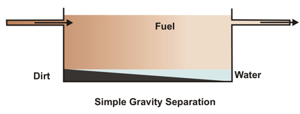
 Basic principle of separation of water and impurities from fuel is gravity difference.
 When a bowl containing impure fuel is rotated, the centrifugal forces throw any item with a density greater than the density of fuel oil (solids and free water) to the bowl ‘s periphery.
 While in operation, a quantity of oil remains in the bowl to form a complete seal around the underside of the top disk and, due to the difference in density, the oil is confined to the outer diameter of the top disk.