Autocollimator – Working Principle, Types, Diagram, Advantages

In this article, we are going to learn about Autocollimator, what it is used for, its working principle, how it works, different types of auto collimator, and its advantages and disadvantages.

What is Autocollimator ?

The autocollimator is an optical instrument which is used for the measurements of small angular differences, changes or deflections. It is also used to determine straightness, flatness, alignment, etc.

Autocolimator working principle

An autocollimator is a device that uses optics to measure small angular variations. This device is extremely sensitive to very small angle changes and can measure angular deviations accurately. It’s essentially a collimator and an infinity telescope combined. Autocollimators are used to align the various components of a system and measure their mechanical or optical deflections.

Parts of an Autocollimator

Six parts of Autocollimator are :-

  • Light source
  • Reflecting surface
  • Diverging lens
  • Beam splitter
  • Target graticule
  • Micrometer microscope

1. Light source

The light source is used to generate light rays so that it reaches the reflector.

2. Reflecting Surface

It is the surface that serves as a workpiece for the autocollimator. The angle of tilt of this reflecting surface is to be measured using the autocollimator. It reflects the parallel light rays that pass through the objective lens.

3. Diverging Lens

The diverging lens, also known as the objective lens, is used to parallelize the light rays that come through the beam splitter so that they reach the reflector in parallel.

4. Beam Splitter

The beam splitter is used to split the light rays and direct it towards the objective lens.

5. Target Graticule

The light rays that have been reflected reach this target graticule, and the distance between the incident and reflected rays is traced in this target graticule.

6. Micrometer Microscope

It is used to clearly see the incident and reflected ray points in the target graticule and measure the distance between them.

Autocollimator Working Principle

An Autocollimator working incorporates two optical principles:

  1. The projection and reception of a parallel beam of light by a lens,
  2. And the change in direction of a beam reflected from a plane surface with changing of angle of the surface.

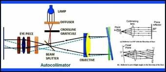
When a monochromatic light source’s beam of light rays falls on a beam deflector, the beam is deflected 90 degrees towards the converging lens. The converging lens parallelizes the beams and directs them to the object or reflecting surface.

To keep the light beam parallel, keep the beam deflector close to the focus of the converging lens. The parallel rays are then directed to strike a reflecting surface or an object. If there are no angular deviations on the object’s surface, the rays reflect back and proceed along the same path, in the opposite direction, eventually converge at the receiver kept at the focal distance from the converging lens. If the object is inclined at an angle, the reflected ray forms an angle with the incident beam of 2(α) degrees.

Let us understand by a example

Imagine, first of all, a converging lens with a point source of light O at its principal focus, as in Figure (a). When a beam of light strikes a flat reflecting surface, a part of the beam is absorbed and the other part is reflected back. If the angle of incidence is zero, i.e. incident rays fall perpendicular to the reflecting surface, the reflected rays retrace the original path as in Figure (a).

When the surface is tilted at any other angle, the total angle through which the light is deflected is twice the angle through which the mirror is tilted, and is brought to a focus in the same plane as the light source but to one side of it, as in Figure (b). Obviously,

OO’ = 20f= x (say), where f is the focal length of the lens.

Thus, by measuring the linear distance QO'(x), the inclination of the reflecting surface o can be determined.

The position of the final image does not depend upon the distance of the reflector from the lens. That is, the separation x is independent of the position of the reflector from the lens. If, however, the reflector is moved too long, the reflected ray will then completely miss the lens and no image will be formed.

In actual practice, the work surface whose inclination is to be obtained forms the reflecting surface and the displacement x is measured by a precision microscope that is calibrated directly to the values of inclination Θ.

Working of Autocollimator

Autocollimator Working

Let’s understand how does an autocollimator work. In autocollimators, the reflective surface is the surface whose inclination is to be measured using this device. A micrometer microscope is used to measure the distance between the source of light and the reflected ray in the focal plane.

First, the light source is illuminated, and the light line’s rays are extracted from the intersection points of the cross line target gratitude, which is placed in the objective lens’s focal plane.

After that, a ray of light reach the beam splitter and the v ray beam is the gate that will direct the light rays towards the objective lens.

The objective lens will parallelize the light rays and the light rays will move towards the reflector.

Now there can be two cases:

Case 1: The reflector is perpendicular to the ray of light.

When parallel light rays reach a reflector that reflector is perpendicular to the light rays, the light rays are reflected back to their original paths. These light rays are then brought into focus in the plane of the target graticule at the intersection of the graticule’s cross lines. Because some of the reflected light passes straight through the beam splitter, the return image of the target crossline is visible through the eyepiece, allowing the telescope to operate as if it were focused at infinity.

Case 2: The reflector is tilted at some angle.

If the reflector is tilted at an angle, the parallel light rays reflect at an angle twice the angle of tilt.
After the reflection, light rays are focused in the plane of the target graticule but linearly displaced from the intersection of crosslines by a distance of 2 * (angle of tilt) *. (focal length of the objective lens).
Depending on whether a visual or digital autocollimator is used, the linear displacement of the graticule image is measured using an eyepiece graticule and a micrometer microscope or an electronic detector system.

Most autocollimators are calibrated so that the distance measured does not need to be converted into the angle of inclination. This is converted in the autocollimator, and the angle of inclination can be read directly there. The focal length and effective aperture of an autocollimator are the factors that determine its basic sensitivity and angular measuring range.

Types of Autocollimator

There are mainly two types of Autocollimator :

1. Visual Autocollimator

In visual autocollimator, the angle of tilt of the reflecting surface is measured by viewing a graduated scale through an eyepiece. As the focal length of the visual autocollimator increases, the angular resolution increases and the field of view decreases. Visual autocollimators can also measure multiple surfaces simultaneously, making them perfect for alignment tasks like checking the parallelism of optical components.

2. Digital Autocollimator

In digital autocollimator, the micrometer adjustment is provided for the setting but the coincidence of setting graticule and the target image is detected photo-electrically. This autocollimator is used in the lab. Digital or electronic autocollimators are used for precise tasks such as calibrating rotary tables, checking angle standards, and providing angular feedback. These devices are significantly more accurate than visual autocollimators, offering up to 100 times greater precision. They also improve repeatability, meaning measurements can be consistently reproduced, and they reduce the time needed for measurements.

What is the formula for the autocollimator?

Formular for Autocollimator

Mathematical formula for the autocollimator : In the above autocollimator diagram, the angle of the y-axis mirror displacement ( α ) is calculated using the formula α = Δy/2f where f = focal length of the autocollimator.

Applications of Autocollimator

Autocollimators are widely used in the optical industry and by mechanical engineers for various applications. Their specific functions include precision alignment, detecting angular movement, verifying angle standards, and monitoring angular changes over long periods.

Testing Applications

Autocollimators are employed in testing:

  • Parallelism with a collimator and telescope
  • Opaque wedges and plane parallel plates
  • Transparent wedges
  • Angles in glass prisms
  • The accuracy of rotary tables and index tables
  • Camera objectives

These optical instruments are also used for testing the flatness of reflecting surfaces, controlling wedges and plane parallel plates, and measuring the parallelism of cylindrical bores.

Measurement Applications

In addition to testing, autocollimators are used to measure:

  • The radius of concave and convex spherical surfaces
  • The back focal length of lenses and optical systems
  • Centration error of spherical surfaces
  • Centration error of lenses in transmission
  • Parallelism or perpendicularity of two surfaces

Additional Applications

Autocollimators also serve in:

  • Measuring the radius of concave and convex spherical surfaces
  • Measuring the relative angular error of prisms
  • Measuring pitch and yaw of slides
  • Setting rolls in parallel
  • Checking the straightness of machine tool slideways
  • Measuring very small angles
  • Checking parallelism
  • Checking the squareness of a column to its base
  • Checking the flatness of bed plates and surface tables
  • Measuring very small displacements
  • Checking small linear displacements

Advantages of Autocollimator

  • It has very high accuracy.
  • It can measure a wide range of angles.
  • It is very easy to install and operate.
  • Calibration surpassing international standards.
  • It can be used to visually or electronically view the result, i.e., on the computer screen.
  • A wide range of available accessories and levels.

Disadvantages of Autocollimator

  • Maintenance is required regularly.
  • It is time-consuming.
  • It requires sample cutting and processing for tracing by the detector.

We have tried to cover all the topics related to Autocollimator, from definition to advantages, disadvantages, types and working principle. If you liked the article , Please share it with your friends.

Frequently Asked Questions – Autocollimator

What is Autocollimation method?

In autocollimation, a collimated beam (of parallel light rays) leaves an optical system and is reflected back into it by a plane mirror. It’s used to determine the minor tilting angles of the mirror.

What is autocollimator used for?

Autocollimator is used for checking straightness, flatness, alignment, and similar measurements in both mechanical and optical systems.

Is autocollimator used for flatness?

Yes, an autocollimator is used to measure flatness. It helps in detecting very small angular deviations and can determine the flatness of surfaces by measuring how much they deviate from a perfectly flat reference plane.

Check Out Other Important Topics

Cast Iron – Properties, Types & Uses

Recovery Recrystallization and Grain Growth – Working Process

Constrained Motion – Definition, Types, Examples, Images

IC EngineImportant PDFsBoilersSynergy Maritime ExamNaval ArchMEO Class 4
Interview QuestionsDifference BetweenTypes of PumpsAuxiliary MachinesTypes of ValvesHome

Understanding the Various Parts of a Ship: A Detailed Guide

Ships, whether for transporting goods or people, are intricate machines requiring a sophisticated combination of design, engineering, and construction. Understanding the various parts of a ship is crucial to ensuring smooth navigation and safe transport.

The anatomy of a ship consists of multiple parts, each with its distinct purpose and function. These parts include the hull, superstructure, propulsion system, navigation and communication equipment, cargo handling equipment, safety equipment, electrical systems, and plumbing and sanitation systems. Knowing how each of these components works is essential in comprehending the ship’s anatomy, construction, and systems.

From the bow to the stern, ships’ parts come in various shapes, sizes, and materials. The design and construction of the vessel must consider its purpose, route, and intended use. Every component plays a vital role in the ship’s overall functionality, stability, and efficiency.

As we explore these ship parts and systems in detail, you will gain a better understanding of how they work together to ensure smooth maritime navigation and efficient transport of goods and people. So, let’s dive into the fascinating world of ship anatomy and construction!

Parts of Ship

Ship Hull

The ship hull is the main body of the vessel that provides buoyancy and stability. It is the outermost layer and is responsible for withstanding the forces of the sea. The hull is made up of several components that work together to form a rigid and durable structure.

Hull Structure

The hull structure is made up of the bottom, sides, and deck of the ship. The bottom of the hull is called the keel, which runs the length of the ship and provides support and stability. The sides of the hull are called the plating or shell and are made of steel or aluminum to withstand the harsh marine environment. The deck is the top of the ship and provides a surface for crew and cargo.

Hull Components

The bow of the ship is the front and is designed to cut through the water efficiently. The stern is the back of the ship and provides propulsion and steering. The rudder, which is attached to the stern, provides directional control. The propeller is also attached to the stern and provides the force needed for movement. The hull also contains various openings such as hatches, vents, and portholes for access and ventilation.

Ship Superstructure: The Brain and Housing of the Vessel

A ship’s superstructure is the upper part of the ship above the main deck, which includes the bridgedeckhouse, and accommodations for the crew and passengers. It serves as the brain and housing of the vessel, containing essential systems and equipment necessary for safe and efficient navigation.

The Bridge

The bridge is the command center of the ship and is located at the front of the superstructure. It provides a panoramic view of the ship’s surroundings and serves as the primary control station for navigation, communication, and maneuvering. The bridge is equipped with essential instruments such as radarGPS, and compasses, which provide real-time data on the ship’s position, speed, and direction.

The Deckhouse

The deckhouse is the main living quarters for the crew and is located behind the bridge. It provides sleeping quarters, a galley, mess hall, and other amenities necessary for the crew’s comfort and well-being during long voyages. The deckhouse may also house other equipment and systems, such as the ship’s fire control center and emergency equipment storage.

Accommodations

The accommodations area is located towards the rear of the superstructure and includes cabins or living quarters for the crew and passengers. These quarters can range from shared rooms to private suites with en-suite bathrooms. The area also includes common areas such as lounges, recreational areas, and medical facilities.

The ship’s superstructure is critical in providing a safe and comfortable environment for the crew and passengers during long voyages. It is also responsible for housing and protecting the essential systems and equipment necessary for navigation, communication, and other ship operations.

Propulsion System

One of the most essential systems onboard a ship is the propulsion system, which provides the necessary power to move the vessel through the water. The propulsion system consists of various components, including the engine roompropellers, and engines.

Engine Room

The engine room is typically located in the lower part of the ship and houses the ship’s engines, generators, and other machinery. It is a critical area that requires constant monitoring and maintenance to ensure the ship’s smooth operation. The engine room is also where the crew can perform repairs and maintenance on the ship’s machinery.

Propellers

Propellers are essential components of a ship’s propulsion system, generating the force that moves the vessel forward or backward. The number and size of the propellers vary depending on the ship’s size and design, and they are typically located at the stern of the ship.

Engines

The type of engine used in a ship depends on the ship’s size, speed, and power requirements. Common types of engines include diesel engines, steam turbines, and gas turbines. They are typically located in the engine room and are responsible for generating the power to turn the propellers and move the ship through the water.

Parts of a ship Diagram

Navigation and Communication Equipment

Navigation and communication equipment are critical systems on any ship, ensuring safe navigation and effective communication with other vessels and shore.

One of the most important pieces of navigation equipment on a ship is radar, which uses radio waves to detect nearby objects. The radar system consists of a transmitter, receiver, and display screen, and it is used to detect and track other vessels and obstacles on the water.

GPS (Global Positioning System) is another essential tool for navigation. It uses satellites to determine a ship’s exact location and provides information such as speed, direction, and distance to other locations.

Communication equipment on a ship includes radios, which allow for communication with other vessels and shore stations. In addition, a ship’s communication system may include satellite phones, email, and other forms of electronic communication.

Most ships also have a bridge navigation system, which integrates radar, GPS, and other navigation tools into a centralized display. This allows for easier navigation and better situational awareness for the ship’s crew.

Risk Management

Effective navigation and communication are critical components of risk management on a ship. By using radar, GPS, and other tools, a ship’s crew can avoid collisions with other vessels and hazards such as reefs and rocks. In addition, effective communication can be the key to obtaining assistance during an emergency.

For these reasons, navigation and communication equipment are among the most important systems on any vessel, and they require careful maintenance and attention to ensure their proper functioning.

Cargo Handling Equipment

The cargo handling equipment on a ship is an essential component of its operations. It allows for the efficient loading, unloading, and securing of cargo, ensuring the timely delivery of goods. The main components of a cargo handling system include cranes and cargo holds.

Cranes

Cranes are used to hoist cargo on and off the ship. They are typically mounted on the ship’s deck and come in various sizes and types. Some cranes are designed to lift heavy loads, while others are more suitable for lighter cargo. Cranes can also be operated manually or electronically, depending on the ship’s specifications.

Modern cargo handling cranes use hydraulic or electric power for their operation. Hydraulic cranes rely on fluid pressure to lift and move heavy loads, making them ideal for handling heavy cargo. Electric cranes use electric motors for movement and are best suited for lighter loads.

Cargo Holds

The cargo hold is the area where the cargo is stored during transportation. It is typically located below the main deck and can be accessed through large doors on the ship’s hull. Cargo holds must be designed to accommodate various types of cargo while ensuring the safety of crew members and the ship.

The cargo hold must also be equipped with various systems to ensure the safety of the cargo during transportation. This includes systems for securing the cargo, monitoring its temperature and humidity, and preventing damage during rough seas.

In summary, the cargo handling equipment on a ship is vital to its operations. The cranes and cargo holds work together to ensure the timely delivery of cargo while maintaining the safety of the crew and the ship.

Safety Equipment

While ships are designed with safety in mind, accidents can still happen at sea. That’s why it’s crucial for ships to have appropriate safety equipment on board. Let’s take a look at some of the most important safety equipment found on ships:

Lifeboats and Life Rafts

Lifeboats and life rafts are essential pieces of safety equipment that are designed to keep passengers and crew members safe in the event of an emergency. Lifeboats can be launched from the deck of the ship and are typically equipped with oars and a motor to help them maneuver in the water. Life rafts are inflatable rafts that can be stored on deck and deployed when needed.

Fire Suppression Systems

Fires can be extremely dangerous on board a ship. That’s why many ships are equipped with fire suppression systems that can help to quickly extinguish any flames that might break out. These systems typically use water, foam, or gases to put out fires.

Emergency Position Indicating Radio Beacons (EPIRBs)

If a ship goes down or becomes stranded at sea, it’s essential for rescuers to be able to locate the ship and its passengers quickly. EPIRBs are small devices that can be activated in an emergency, sending out a distress signal that can be picked up by rescue teams. These devices are typically waterproof and can be attached to life jackets or other safety equipment.

Personal Flotation Devices (PFDs)

Whenever someone is on board a ship, it’s important for them to have a PFD readily available. PFDs are designed to keep a person afloat in the water and can be used to help someone stay safe while waiting for rescue. PFDs come in many different styles, including vests and inflatable devices.

These are just a few of the many safety features that can be found on modern ships. By ensuring that a ship is equipped with the appropriate safety equipment, crew members and passengers can sail with confidence and peace of mind.

All Parts of ship

Electrical Systems

Ship electrical systems are crucial for powering various components and systems on board, ranging from navigation and communication equipment to cargo handling mechanisms and safety systems. These systems are responsible for generating and distributing electricity throughout the vessel, ensuring that all areas receive the power necessary to operate effectively.

Power Generation

The power generation process begins in the engine room, where generators are used to convert mechanical energy into electrical energy. The size and number of generators depend on the ship’s size and power requirements.

On most vessels, generators are powered by diesel engines, although some ships may also use gas turbines or other alternative fuel sources. Once generated, electricity is distributed to different parts of the ship through a network of wires and cables.

Wiring and Distribution

Ship electrical systems rely on a complex network of wiring and distribution panels to transport electricity throughout the vessel. These wiring systems are designed to handle high levels of power and must be able to withstand the harsh marine environment without corroding or degrading.

Electrical distribution panels are used to regulate the flow of electricity to different parts of the ship, ensuring that each system receives the appropriate amount of power. These panels are often located in the engine room or other central locations on the vessel.

Lighting

Ship lighting is an essential component of the vessel’s electrical systems. Adequate lighting is necessary for maintaining safe navigation, ensuring that crew members can see and operate machinery and equipment effectively.

LED lighting fixtures are becoming increasingly popular in ship design due to their energy efficiency and longer lifespan compared to traditional lighting sources. Some vessels may also use colored lighting to assist with nighttime navigation or signaling.

Plumbing and Sanitation Systems

The plumbing and sanitation systems on board a ship are crucial for ensuring the health and wellbeing of the crew members. Proper maintenance and operation of these systems are essential for the efficient and safe operation of the vessel.

The ship’s plumbing system is responsible for supplying fresh water to all areas of the vessel. It includes various pipes, pumps, and valves that must be maintained and inspected regularly. Any leaks or malfunctions in the plumbing system can lead to water damage, loss of fresh water supply, or even flooding.

In addition to supplying fresh water, the ship’s plumbing system also handles wastewater and sewage. Sanitation systems on board the vessel are crucial for managing this waste and preventing pollution of the surrounding environment. Wastewater treatment systems are used to filter and treat sewage, ensuring that it is safe to discharge into the ocean.

Proper hygiene practices on board the ship are also essential for preventing the spread of disease and maintaining a healthy living environment for crew members. Sanitation systems play a critical role in preventing the spread of germs and illnesses. Regular cleaning and maintenance of these systems help to ensure that they are operating effectively.

Overall, the plumbing and sanitation systems on board a ship are critical components that must be maintained and operated properly. Failure to do so can result in serious consequences for the crew members and the environment. By adhering to proper maintenance and operating procedures, ship operators can ensure that these vital systems operate effectively and safely.

Conclusion

In conclusion, understanding the various parts of a ship is crucial for maritime navigation and safety. Ship parts such as the hull, superstructure, propulsion system, navigation and communication equipment, cargo handling equipment, safety equipment, electrical systems, and plumbing and sanitation systems all play essential roles in ensuring a ship operates efficiently and safely.

By familiarizing oneself with vessel parts and maritime terminology, one can gain a greater appreciation for the complexity of ship structure and construction. Additionally, this can provide insight into the importance of regular maintenance and upkeep to ensure the ship’s systems are functioning optimally.

Whether one is a professional mariner or simply interested in ships and maritime travel, knowledge of ship anatomy and systems is a valuable asset. We hope this detailed guide has been informative and helpful in providing a comprehensive overview of the various parts of a ship.

FAQ

Why is it important to understand the different parts of a ship?

Understanding the different parts of a ship is important because it allows for better navigation, maintenance, and overall operation of the vessel. It helps ensure the safety of the crew, passengers, and cargo onboard.

What is the ship’s hull and what is its purpose?

The ship’s hull is the outer shell or body of the ship. It provides structural strength, buoyancy, and protection against the elements. The hull also helps to minimize water resistance and provides stability to the ship.

What components make up the ship’s hull?

The ship’s hull is made up of various components, including the bow (front), stern (rear), keel (bottom), bulkheads (internal walls), and frames (ribs). These components work together to form the overall structure of the ship.

What is the superstructure of a ship?

The superstructure of a ship includes the bridge, deckhouse, and accommodations. It is located above the main deck and houses essential equipment, navigation systems, and provides living quarters for the crew.

What is the propulsion system of a ship?

The propulsion system of a ship is responsible for generating the power needed to move the vessel through water. It typically includes engines, propellers, and various supporting systems like fuel storage and cooling.

What navigation and communication equipment are found on ships?

Ships are equipped with navigation systems such as radar, GPS, and compasses to determine their position and navigate safely. Communication equipment includes radios, satellite systems, and other technologies for effective communication with shore and other vessels.

What is cargo handling equipment on a ship?

Cargo handling equipment refers to the machinery and systems used to load, unload, and secure cargo on a ship. This includes cranes, cargo holds, conveyor belts, and other mechanisms that ensure efficient cargo operations.

What safety equipment is found on ships?

Ships are equipped with various safety measures, including lifeboatslife raftsfire suppression systems, emergency lights, and alarms. These are in place to protect the crew and passengers in case of emergencies.

What are the electrical systems on a ship?

Electrical systems on ships include power generation, distribution, wiring, and lighting. They provide power to various components and systems on board, ensuring the proper functioning of navigation equipment, communication systems, and other electrical devices.

What plumbing and sanitation systems are found on ships?

Ships have plumbing systems that provide water supply, wastewater treatment systems, and facilities for maintaining hygienic conditions onboard. These systems are essential for the well-being and comfort of the crew and passengers.

Check Out Other Important Topics

IC EngineImportant PDFsBoilersSynergy Maritime ExamNaval ArchMEO Class 4
Interview QuestionsDifference BetweenTypes of PumpsAuxiliary MachinesTypes of ValvesHome

Electric Arc Furnace – Complete Process, Parts & Application

What is electric arc furnace

An electric arc furnace (EAF) is a type of industrial furnace used for melting metals, particularly steel and iron, through the use of an electric arc. It’s a crucial tool in the steelmaking industry and is known for its efficiency and flexibility in producing various steel grades.

Electric Arc Furnace diagram

parts of electric arc furnace

An electric arc furnace (EAF) is a complex industrial furnace with several key parts and components that work together to melt and refine metals. Here are the main parts of an electric arc furnace:

  1. Shell: The shell is the outer structure of the EAF, typically made of steel and lined with refractory materials. It provides structural support and helps contain the heat and materials inside the furnace.
  2. Lid or Roof: The lid, also known as the roof, is the top cover of the furnace. It can be lifted or rotated to allow for charging of raw materials and removal of molten metal and slag. It also contains openings for electrodes and various ports for operations like oxygen injection.
  3. Electrodes: Electrodes are typically made of graphite or other conductive materials and are inserted through openings in the roof. They create an electric arc when electricity is passed through them, generating the high temperatures needed for melting metals.
  4. Furnace Hearth: The hearth is the bottom portion of the furnace, where molten metal collects. It is lined with refractory materials that can withstand the extreme heat of the molten metal.
  5. Refractory Lining: The refractory lining is a layer of heat-resistant materials that line the inside of the furnace, including the walls, roof, and hearth. These materials protect the steel shell from the intense heat generated during the melting process.
  6. Electrode Holders: Electrode holders secure the electrodes in place and allow for adjustments to control the position of the electric arc.
  7. Transformer: Electric arc furnaces require a high voltage electrical supply to generate the electric arcs. A transformer is used to step up the voltage from the power source to the level needed for the EAF operation.
  8. Electrical System: The electrical system includes components such as transformers, circuit breakers, switches, and control panels to manage the flow of electricity to the electrodes and other furnace systems.
  9. Cooling System: EAFs generate a tremendous amount of heat, and a cooling system is essential to prevent overheating and maintain the integrity of the furnace components. Water-cooled panels, pipes, and cooling jackets are commonly used for this purpose.
  10. Gas Injection System: Some EAFs are equipped with a gas injection system that introduces gases like oxygen or argon into the furnace. These gases can affect the melting process and help in refining the metal.
  11. Dust and Fume Collection System: EAF operations can generate dust and fumes, which need to be collected and filtered to reduce environmental impact and protect worker health.
  12. Tapping System: A tapping system includes equipment such as a tap hole, tap spout, and ladle, which are used to safely remove molten metal and slag from the furnace for further processing or casting.
  13. Control and Automation System: Modern EAFs are often equipped with sophisticated control and automation systems that monitor and regulate various parameters, such as temperature, electrode position, and power input, to ensure efficient and precise melting.

These are the primary components of an electric arc furnace, and their design and operation can vary depending on the specific requirements of the metal production process and the type of materials being melted and refined.

Electric Arc Furnace Parts

Electric arc furnace process

The electric arc furnace (EAF) process is a step-by-step method used in the melting and refining of metals, particularly steel. Here’s a simplified step-by-step description of how an EAF typically operates:

  1. Charging: The process begins by loading the raw materials into the EAF. These materials can include scrap steel, iron ore, alloying elements, and fluxes. The materials are typically charged from the top of the furnace through an opening in the roof or lid.
  2. Electrode Placement: Electrodes, usually made of graphite, are positioned in the furnace roof’s electrode holders. These electrodes will create an electric arc, generating the intense heat needed for melting the materials.
  3. Start-Up: The EAF is energized, and electrical power is supplied to the electrodes. When the electrodes touch the materials in the furnace, an electric arc is established between the electrodes and the charge materials, initiating the melting process.
  4. Melting: The electric arc generates extremely high temperatures, often exceeding 3,000 degrees Celsius (5,432 degrees Fahrenheit). This intense heat melts the materials in the furnace, including the scrap steel and any other added components like alloys.
  5. Oxygen Injection (Optional): In some cases, oxygen or other gases can be injected into the furnace to accelerate the combustion of impurities, aid in chemical reactions, and enhance the melting process. This step is optional and depends on the specific steelmaking process.
  6. Chemical Reactions: As the materials melt, chemical reactions occur within the furnace. Impurities in the scrap steel are oxidized and removed as slag, while alloying elements are added to achieve the desired steel composition.
  7. Temperature Control: The EAF’s control system continuously monitors and adjusts the electric arc’s power and position to maintain the desired temperature and composition of the molten metal.
  8. Sampling and Analysis: Samples of the molten metal are periodically taken to assess its chemical composition and temperature. This information helps operators make necessary adjustments to meet quality standards.
  9. Refining: Depending on the steel grade being produced, additional refining steps may be performed. These can include adding fluxes or alloying materials to achieve specific metallurgical properties.
  10. Tapping: When the molten metal has reached the desired composition and temperature, a tap hole in the bottom of the furnace is opened, allowing the molten steel to flow into a ladle or casting vessel. Simultaneously, slag is also removed from the furnace.
  11. Ladle Transfer: The molten steel is transferred from the EAF to a ladle for further processing. It may be transported to a secondary refining process, such as a ladle furnace, to further refine the steel’s composition and temperature.
  12. Casting: The refined molten steel is cast into various shapes, such as slabs, billets, or ingots, depending on the intended use. The casting process can vary depending on the specific steel product being produced.
  13. Cooling and Solidification: The cast steel is allowed to cool and solidify, forming the final product. The cooling process can be controlled to achieve specific microstructures and mechanical properties.
  14. Quality Control: The finished steel products are subjected to quality control measures to ensure they meet the required standards and specifications.

The EAF process offers flexibility, efficiency, and control in steelmaking, making it a preferred method for producing a wide range of steel products while also recycling scrap metal. The specific steps and details of the process can vary depending on the type of steel being produced and the equipment used in the EAF.

The Electric Arc furnace

Application of electric arc furnace

Electric arc furnaces (EAFs) have a wide range of applications, primarily in the metallurgical and manufacturing industries. Here are some key applications of electric arc furnaces:

  1. Steel Production: EAFs are commonly used for steelmaking. They melt scrap steel, iron ore, and various alloying elements to produce different grades of steel. This process is essential for manufacturing a wide range of steel products, including construction materials, automotive components, and machinery parts.
  2. Stainless Steel Production: EAFs are crucial for producing stainless steel, which is highly resistant to corrosion and heat. The EAF process allows for precise control over the composition of stainless steel, making it suitable for various applications in the chemical, food processing, and medical industries.
  3. Ferroalloy Production: Electric arc furnaces are used to produce ferroalloys, which are alloys of iron with other elements like silicon, manganese, or chromium. Ferroalloys are essential for enhancing the properties of steel and manufacturing specialized alloys used in various industries.
  4. Cast Iron Production: Some EAFs are designed for producing cast iron, which is used in the production of pipes, fittings, engine blocks, and other heavy-duty applications.
  5. Non-Ferrous Metal Production: While EAFs are most commonly associated with steel and iron production, they can also be used to melt and refine non-ferrous metals like copper, aluminum, and nickel. This is important for recycling and refining these metals.
  6. Recycling: EAFs play a critical role in recycling scrap metal. They can quickly melt down and refine various types of scrap, reducing the environmental impact of metal production and conserving natural resources.
  7. Specialty Alloys: Electric arc furnaces are used to create specialty alloys with precise chemical compositions. These alloys find applications in aerospace, electronics, and other high-tech industries.
  8. Heat Treatment: In addition to melting metals, EAFs can be used for heat treatment processes, such as annealing or tempering, to improve the mechanical properties of steel and other materials.
  9. Research and Development: EAFs are used in research and development settings to experiment with new alloy compositions and refine manufacturing processes.
  10. Environmental Remediation: In some cases, EAFs are employed for the decontamination and treatment of hazardous waste materials, helping to neutralize pollutants and reduce their environmental impact.

Electric arc furnaces are versatile and efficient tools in the manufacturing world, and their applications continue to expand as technology advances and industries seek more sustainable and cost-effective ways to produce metals and alloys.

Electric Arc Furnace 1

Advantages of electric arc furnace

Electric arc furnaces (EAFs) offer several advantages in various industrial applications, making them a popular choice for melting and refining metals. Here are some of the key advantages of using electric arc furnaces:

  1. Energy Efficiency: EAFs are generally more energy-efficient than other types of furnaces, such as blast furnaces. They can quickly reach and maintain high temperatures, reducing energy consumption and costs.
  2. Flexibility: EAFs can easily switch between different types of raw materials, including scrap metal, iron ore, and alloys. This flexibility allows manufacturers to adapt to changing market demands and recycle scrap materials effectively.
  3. Environmental Benefits: EAFs emit fewer greenhouse gases and pollutants compared to traditional steelmaking methods like blast furnaces. This contributes to lower carbon emissions and improved air quality.
  4. Lower Capital Costs: Building and maintaining EAFs tend to be more cost-effective than constructing and operating blast furnaces, which are larger and more complex facilities.
  5. Quick Start-Up and Shutdown: EAFs can be started and stopped quickly, making them ideal for handling fluctuating production demands and reducing downtime.
  6. Precise Temperature Control: Electric arc furnaces offer precise temperature control, which is crucial for achieving specific metallurgical properties and producing high-quality alloys.
  7. Custom Alloy Production: EAFs allow for the production of custom alloys with precise chemical compositions, catering to the needs of various industries.
  8. Recycling Capabilities: EAFs are excellent for recycling scrap metal, reducing the environmental impact of metal production and conserving natural resources.
  9. Reduced Waste: The EAF process generates less waste material compared to other melting and refining methods, reducing disposal costs and environmental impact.
  10. Lower Noise Levels: Electric arc furnaces typically produce less noise compared to some other industrial processes, creating a safer and more comfortable working environment for operators.
  11. Improved Safety: EAFs have safety features that help prevent accidents and protect workers from exposure to extreme heat and harmful substances.
  12. Modularity: EAFs can be designed in various sizes and configurations, allowing companies to scale their operations up or down as needed.
  13. High Product Quality: With precise control over temperature and composition, EAFs can consistently produce high-quality metals and alloys, meeting stringent industry standards.
  14. Reduced Lead Times: EAFs can significantly reduce lead times in metal production because of their quick start-up and operational flexibility.
  15. Lower Maintenance Costs: Electric arc furnaces generally have lower maintenance requirements compared to some other types of furnaces, which can lead to cost savings over time.

These advantages make electric arc furnaces a preferred choice for a wide range of applications in the metallurgical and manufacturing industries, including steelmaking, alloy production, and metal recycling. Additionally, their energy efficiency and reduced environmental impact align with sustainability goals and regulatory requirements.

Disadvantages of electric arc furnace

While electric arc furnaces (EAFs) offer many advantages, they also have some disadvantages and limitations that need to be considered in industrial applications. Here are some of the key disadvantages of using electric arc furnaces:

  1. High Electricity Consumption: EAFs require a substantial amount of electrical power to generate the electric arc and maintain high temperatures. This can result in significant electricity costs, especially during periods of high energy prices.
  2. Initial Investment Costs: The capital cost of installing an EAF can be high, particularly for larger furnaces with advanced features and pollution control equipment. This initial investment can be a barrier for smaller companies or those with limited resources.
  3. Limited Capacity: EAFs have a limited capacity compared to some other types of furnaces like blast furnaces. This limitation can be a constraint for companies with high production demands.
  4. Variable Scrap Quality: When using scrap metal as a raw material, the quality and composition of the scrap can vary, which can lead to variations in the final product’s quality and composition.
  5. Dust and Emissions: EAFs can generate dust and emissions, including particulate matter and volatile organic compounds. To address environmental concerns, additional equipment and processes may be needed for emissions control and dust collection.
  6. Consumable Electrodes: The electrodes used in EAFs are consumable and need to be replaced periodically. This incurs additional maintenance and operating costs.
  7. Maintenance Requirements: While EAFs generally have lower maintenance requirements compared to some other furnace types, they still require regular maintenance to ensure optimal performance and longevity.
  8. Noise and Vibration: EAFs can produce noise and vibration during operation, which may require measures to protect workers and minimize the impact on nearby communities.
  9. Reliability: The electrical components of EAFs, such as transformers and power supplies, can be susceptible to malfunctions or breakdowns, leading to production disruptions.
  10. Safety Concerns: Working with high temperatures and electrical currents poses inherent safety risks. Proper safety measures and training are essential to prevent accidents.
  11. Specialized Expertise: Operating and maintaining EAFs requires specialized knowledge and expertise, which can limit the pool of qualified personnel and increase labor costs.
  12. Raw Material Handling: EAFs rely on a steady supply of raw materials, which must be properly sorted, prepared, and loaded into the furnace. Inconsistent or inefficient material handling can affect production efficiency.
  13. Environmental Regulations: Meeting stringent environmental regulations, especially regarding emissions and waste management, can add complexity and cost to EAF operations.
  14. Production Interruptions: EAFs may need to be shut down for maintenance or electrode replacement, leading to temporary production interruptions.
  15. Size Limitations: The physical size and design of EAFs can limit their application in some industries or for specific products that require larger or differently shaped furnaces.

Despite these disadvantages, electric arc furnaces remain a valuable and widely used tool in the metallurgical and manufacturing industries, especially when their advantages, such as flexibility and environmental benefits, align with specific production requirements and objectives. Advances in technology continue to address some of these limitations over time.

blast furnace vs electric arc furnace

Here’s a comparison table between a blast furnace and an electric arc furnace (EAF) based on various key aspects:

AspectBlast FurnaceElectric Arc Furnace (EAF)
Primary UseProduction of primary iron from iron oreMelting and refining of scrap metal and alloys
Raw MaterialsIron ore, coke, limestone, and additivesScrap metal, ore, alloys, and additives
Energy SourceCoke and coal for heatingElectricity for generating electric arcs
TemperatureExtremely high temperatures (above 2,000°C)Very high temperatures (above 3,000°C)
Environmental ImpactHigh greenhouse gas emissionsLower greenhouse gas emissions
EfficiencyLower energy efficiencyHigher energy efficiency
FlexibilityLimited flexibility in raw material useGreater flexibility with scrap metal
Production ScaleTypically large-scale operationsSuitable for both large and small-scale operations
Start-Up TimeLonger start-up time (days)Shorter start-up time (hours)
Continuous OperationOften continuous operationEasily adaptable to fluctuating demand
Quality ControlLimited control over compositionPrecise control over composition and temperature
MaintenanceHigh maintenance due to wear and tearLower maintenance requirements
Initial InvestmentHigh capital investmentVaries based on size and capacity
RecyclingNot suitable for recycling scrap metalIdeal for recycling scrap metal
End ProductsPig iron, which requires further processingMolten metal for various applications
Environmental BenefitsLower air pollution, but high CO2 emissionsLower air pollution, reduced CO2 emissions, and energy efficiency benefits

Please note that the comparison is based on general characteristics, and specific operations and results can vary depending on the design and technology used in individual blast furnaces and EAFs. The choice between these two methods depends on factors like the type of metal production, raw materials available, and environmental considerations.

Check Out Other Important Topics

IC EngineImportant PDFsBoilersSynergy Maritime ExamNaval ArchMEO Class 4
Interview QuestionsDifference BetweenTypes of PumpsAuxiliary MachinesTypes of ValvesHome

Scrubber – Working, Types, Components & Application

What is Scrubber

A scrubber, in a general sense, is a device or system designed to cleanse or remove unwanted substances, pollutants, or contaminants from a gas, liquid, or air stream. It’s used to improve the quality of the treated medium by eliminating harmful elements. Scrubbers find applications in various industries and environmental settings to reduce pollution, ensure compliance with regulations, and enhance overall safety and cleanliness. The term “scrubber” can refer to different technologies and methods depending on the context in which it’s used.

Wet scrubber

components of scrubber

A scrubber, particularly in an industrial air pollution control context, consists of several key components that work together to remove pollutants and contaminants from gas streams. The specific components can vary depending on the type of scrubber technology used, but here are the fundamental components you might find in a typical wet scrubber system:

  1. Inlet Duct: This is the point where the contaminated gas enters the scrubber system. The inlet duct directs the gas flow into the scrubber unit.
  2. Absorption Tower or Chamber: This is the main body of the scrubber where the actual pollutant removal takes place. It contains the scrubbing medium, which can be water or a chemical solution, depending on the pollutants being targeted.
  3. Spray Nozzles: These are used to introduce the scrubbing liquid (often water) into the absorption chamber in the form of fine droplets. These droplets come into contact with the contaminated gas, promoting absorption of pollutants.
  4. Packing Material or Tray: In some scrubbers, there might be structured packing material or trays inside the absorption chamber. These increase the contact surface area between the gas and the scrubbing liquid, enhancing pollutant absorption.
  5. Mist Eliminator or Demister: After the gas has passed through the absorption chamber, it might carry small liquid droplets with it. A mist eliminator is used to capture and remove these droplets, ensuring that only cleaned gas exits the scrubber.
  6. Outlet Duct: This is where the cleaned gas exits the scrubber system and is released into the environment or further processing.
  7. Pump: In systems that use a liquid scrubbing medium, a pump is used to circulate the scrubbing solution from the bottom of the absorption chamber to the spray nozzles at the top.
  8. Blower or Fan: Depending on the system design, a blower or fan might be used to help move the gas through the scrubber unit and ensure proper gas-liquid contact.
  9. Monitoring and Control Instruments: These include sensors, gauges, and controllers that measure parameters like gas flow rate, pressure, temperature, pH levels, and pollutant concentrations. This data helps optimize the scrubber’s performance and ensure compliance with regulatory standards.
  10. Recirculation System: In some scrubbers, a recirculation loop might be present to enhance pollutant absorption. This involves circulating a portion of the scrubbed liquid back into the absorption chamber.
  11. Drain System: As pollutants are absorbed by the scrubbing liquid, a drain system is used to remove the liquid containing the pollutants from the bottom of the absorption chamber for further treatment or disposal.

The exact components and their arrangement can vary based on the type of scrubber technology being used, such as wet scrubbers, dry scrubbers, or specific variations like venturi scrubbers or packed bed scrubbers.

Scrubber Diagram

How does scrubber works

A scrubber works by using various mechanisms to remove pollutants and contaminants from gas streams. The exact working principle can vary depending on the type of scrubber being used (wet, dry, electrostatic, etc.), but here’s a general overview of how a wet scrubber, one of the most common types, works:

Wet Scrubber Working Principle:

  1. Gas Entry: The gas stream containing pollutants enters the scrubber through an inlet duct or chamber.
  2. Contact/Reaction Chamber: In this chamber, the gas stream comes into contact with a scrubbing liquid (usually water or a chemical solution). The scrubbing liquid can be sprayed, cascaded, or allowed to flow over surfaces, creating a large contact area between the gas and the liquid.
  3. Particle Capture: As the gas passes through the scrubbing liquid, various mechanisms come into play to capture pollutants:
  • Impaction: Larger particles are captured when they collide with droplets of the scrubbing liquid.
  • Adsorption: Gaseous pollutants may be absorbed into the liquid through physical or chemical processes.
  • Chemical Reactions: Some pollutants react chemically with the scrubbing liquid, forming compounds that can be collected.

4.Droplet Formation: The scrubbing liquid breaks into small droplets, increasing the surface area available for gas-liquid interaction. This maximizes the chances of pollutants being captured.

5.Packing Material (if applicable): In scrubbers that use packing material, such as packed bed scrubbers, the gas passes through a structured arrangement of materials. This increases the surface area even further, enhancing pollutant capture.

6.Mist Elimination: After the gas passes through the contact chamber, it might still carry small liquid droplets. A mist eliminator or demister removes these droplets from the gas stream, preventing liquid carryover.

7.Cleaned Gas Exit: The gas stream, now stripped of a significant portion of its pollutants, exits the scrubber through an outlet duct or stack.

8.Slurry or Liquid Collection (if applicable): In some cases, a scrubber generates a liquid slurry containing captured pollutants. This slurry needs to be collected, treated, and disposed of properly according to environmental regulations.

9.Controls and Monitoring: Modern scrubber systems often include controls and monitoring devices that adjust the flow rates of gas and liquid, maintain optimal pH levels, and ensure efficient operation.

The specific working mechanisms might differ based on the type of pollutants, scrubbing liquid, and design of the scrubber. The ultimate goal of a scrubber is to effectively remove pollutants from gas streams, reducing emissions and contributing to improved air quality and environmental compliance.

types of scrubber

There are several types of scrubbers used in various industries to remove pollutants and contaminants from gas streams. Each type of scrubber is designed to address specific types of pollutants and operating conditions. Here are some common types of scrubbers:

1. Wet Scrubbers:

  • Venturi Scrubbers: These scrubbers create a constriction in the gas stream, causing turbulence and enabling the mixing of pollutants with a scrubbing liquid. The turbulence helps capture particles and gases.
  • Packed Bed Scrubbers: These scrubbers use a packed bed of materials like structured packing or random packing to increase the contact surface area between the gas and the scrubbing liquid, enhancing pollutant absorption.
  • Spray Tower Scrubbers: In these scrubbers, the gas stream passes through a chamber where the scrubbing liquid is sprayed from nozzles. The liquid droplets capture pollutants as they come into contact with the gas.
  • Bubble Cap Tray Scrubbers: Similar to spray tower scrubbers, but instead of sprays, gas passes through bubble cap trays where scrubbing liquid flows over the trays and creates bubbles that capture pollutants.
  • Impingement Plate Scrubbers: Gas and liquid are forced to collide on impingement plates, promoting the capture of particles through impaction and subsequent liquid droplet collection.

2. Dry Scrubbers:

  • Dry Sorbent Injection (DSI) Systems: Dry sorbents like lime or sodium bicarbonate are injected into the gas stream, reacting with acidic gases to form solid byproducts that can be collected.
  • Spray Dry Scrubbers: These scrubbers use a dry sorbent sprayed into the gas stream as fine droplets. The gas-solid reactions occur as the droplets dry, capturing pollutants.
  • Fluidized Bed Scrubbers: In fluidized bed scrubbers, dry sorbents are suspended in an upward-flowing gas stream. Pollutants react with the sorbent particles as they circulate in the fluidized bed.

3. Electrostatic Precipitators (ESPs):

  • While not traditional wet or dry scrubbers, ESPs are electrostatic devices that use an electric field to charge and collect particulate matter and aerosols from gas streams.

4. Gas Absorption Scrubbers:

  • Ammonia Scrubbers: These scrubbers use a scrubbing solution to absorb and neutralize ammonia gas from industrial processes.
  • Hydrogen Sulfide Scrubbers: Scrubbers designed to remove hydrogen sulfide gas from gas streams, often used in wastewater treatment and biogas facilities.

5. Selective Catalytic Reduction (SCR):

  • SCR systems use catalysts to facilitate chemical reactions that convert nitrogen oxides (NOx) into nitrogen gas and water vapor, reducing NOx emissions.

6. Activated Carbon Adsorption:

  • Activated carbon scrubbers use adsorption to capture volatile organic compounds (VOCs) and other pollutants from gas streams.

The choice of scrubber type depends on factors such as the specific pollutants to be removed, gas flow rates, temperature, humidity, and regulatory requirements. Industries select the most suitable scrubber technology to effectively and efficiently meet their emission control needs.

Scrubber Working

application of Scrubber

Scrubbers have diverse applications across various industries and environmental contexts. Some of the key applications of scrubbers include:

  1. Industrial Emission Control: Scrubbers are extensively used in industries such as power generation, manufacturing, and chemical production to remove harmful gases like sulfur dioxide (SO2), nitrogen oxides (NOx), hydrogen chloride (HCl), and particulate matter from exhaust gases before they are released into the atmosphere.
  2. Air Quality Improvement: Scrubbers play a vital role in improving the air quality of urban and industrial areas by reducing emissions of pollutants that contribute to smog, acid rain, and respiratory illnesses.
  3. Wastewater Treatment: In water treatment facilities, scrubbers are employed to remove contaminants from wastewater and industrial effluents, ensuring that harmful substances do not contaminate natural water bodies.
  4. Marine Industry: Marine scrubbers, often referred to as exhaust gas cleaning systems (EGCS), are used in ships to remove sulfur oxides from the exhaust gases of marine engines, helping vessels comply with international emission standards.
  5. Mining Operations: Scrubbers are used to control dust emissions in mining and mineral processing operations, preventing the dispersion of harmful particles into the surrounding environment.
  6. Chemical Processing: Scrubbers are employed in chemical plants to neutralize or remove hazardous fumes and byproducts produced during various chemical reactions.
  7. Oil and Gas Industry: In oil refineries and natural gas processing plants, scrubbers help remove sulfur compounds and other pollutants from process gases to meet regulatory requirements.
  8. Food Processing: Scrubbers can be used in food processing facilities to control odors and remove airborne contaminants from cooking or production processes.
  9. Laboratories and Cleanrooms: Scrubbers help maintain sterile and controlled environments in laboratories, cleanrooms, and medical facilities by filtering out airborne particles and contaminants.
  10. Agricultural Operations: Scrubbers can be used in agricultural settings to mitigate odors and gases produced by livestock operations and waste management facilities.
  11. Nuclear Industry: Scrubbers are used in nuclear power plants to remove radioactive particles from the air, enhancing safety and preventing the release of radioactive substances.
  12. Electronics Manufacturing: In semiconductor manufacturing and electronics assembly, scrubbers help control airborne contaminants and maintain clean conditions essential for production processes.
Industrial-Scrubbers

The specific type of scrubber and its design depend on the application and the pollutants or contaminants that need to be removed. Scrubbers play a crucial role in reducing environmental impacts, improving health and safety, and ensuring compliance with regulations across a wide range of industries.

Advantages of Scrubber

Scrubbers offer several advantages in a variety of industrial and environmental settings. Some of the key advantages of using scrubbers include:

  1. Pollution Control: Scrubbers are highly effective in removing pollutants and contaminants from exhaust gases, liquids, and air streams. They contribute to reducing emissions of harmful substances, thereby mitigating air and water pollution.
  2. Compliance with Regulations: Industries are often subject to strict environmental regulations and emissions standards. Scrubbers enable companies to meet these requirements by significantly reducing emissions of pollutants, helping avoid penalties and legal issues.
  3. Improved Air Quality: By removing harmful gases and particulate matter from industrial exhausts, scrubbers play a crucial role in improving overall air quality. This is essential for protecting human health and the environment.
  4. Health and Safety: Scrubbers enhance workplace safety by reducing exposure to toxic fumes, hazardous gases, and airborne particulates. This is especially important in industries where employees are at risk of exposure to harmful substances.
  5. Preventing Acid Rain: Scrubbers that remove sulfur dioxide (SO2) and nitrogen oxides (NOx) from exhaust gases help prevent the formation of acid rain, which can damage ecosystems, soil, water bodies, and infrastructure.
  6. Odor Control: In various industries, scrubbers are used to eliminate foul odors generated during manufacturing processes, wastewater treatment, and other operations. This helps create a more pleasant environment for workers and nearby communities.
  7. Reduced Corrosion: Scrubbers can reduce the presence of corrosive gases in industrial exhaust, which helps extend the lifespan of equipment and infrastructure, leading to cost savings.
  8. Energy Recovery: Some scrubber designs allow for the recovery of energy or valuable chemicals from the captured pollutants, turning a potential waste stream into a resource.
  9. Versatility: Scrubbers can be designed to handle a wide range of pollutants, making them versatile solutions for various industries and applications.
  10. Public Relations and Reputation: Implementing effective pollution control measures, such as using scrubbers, demonstrates a company’s commitment to environmental responsibility, which can enhance its reputation among stakeholders and the public.
  11. Global Environmental Impact: Widespread use of scrubbers contributes to global efforts to mitigate climate change and reduce the release of greenhouse gases and other pollutants into the atmosphere.
  12. Customization: Scrubbers can be tailored to suit specific industrial processes and pollution control needs, ensuring optimal performance.

While scrubbers offer numerous advantages, their implementation should be carefully planned to ensure proper design, operation, and maintenance. This ensures that the desired benefits are achieved without any unintended negative consequences.

Packed Tower Scrubber

Disadvantages of Scrubber

While scrubbers offer numerous benefits, they also come with certain disadvantages and challenges that should be considered. Some of the disadvantages of scrubbers include:

  1. Initial Cost: The installation of scrubber systems can involve significant upfront costs, including equipment purchase, engineering, installation, and integration with existing processes. This cost factor can be a deterrent for some industries, especially smaller businesses.
  2. Maintenance and Operating Costs: Scrubber systems require regular maintenance, monitoring, and operational costs. This includes expenses for replacing scrubber media, cleaning components, and addressing potential technical issues.
  3. Energy Consumption: Certain types of scrubbers can consume a notable amount of energy to operate efficiently, potentially offsetting the environmental benefits gained from pollutant removal.
  4. Complexity: The design, installation, and operation of scrubber systems can be complex, requiring specialized knowledge and skilled personnel to ensure optimal performance.
  5. Space Requirements: Scrubbers may require dedicated physical space within an industrial facility, which can be challenging to accommodate, particularly in crowded or confined settings.
  6. Waste Management: Scrubber systems generate waste products, such as captured pollutants or spent scrubbing solutions, which must be properly managed and disposed of according to regulations.
  7. Chemical Usage: Some scrubber systems require the use of chemicals or reagents to facilitate pollutant removal. The handling, storage, and disposal of these chemicals can introduce additional complexities and environmental considerations.
  8. Byproduct Generation: While some scrubbers may recover valuable byproducts, others may generate waste streams that need proper treatment, potentially leading to additional costs and environmental concerns.
  9. Efficiency Trade-offs: Depending on the design and operation, certain scrubber systems might have trade-offs in terms of pollutant removal efficiency versus energy consumption or cost-effectiveness.
  10. Limited Effectiveness for Certain Pollutants: Scrubbers might not be equally effective at removing all types of pollutants. Some gaseous compounds, such as volatile organic compounds (VOCs), might require specialized scrubber technologies for effective removal.
  11. Environmental Impact: The production, maintenance, and disposal of scrubber components can have their own environmental impact, potentially offsetting some of the benefits gained from pollutant removal.
  12. Transition Period: Retrofitting existing industrial processes with scrubbers might require temporary shutdowns or adjustments, impacting production and operations during the transition.
  13. Water Usage: Wet scrubbers, which rely on water for pollutant capture, can have water usage implications in regions where water resources are scarce.
  14. Maintenance Downtime: Scheduled maintenance and occasional unexpected downtimes for maintenance or repairs can disrupt industrial operations.
  15. Specific Applications: Some industries or processes might have unique challenges that make the implementation of scrubbers less practical or effective for certain pollutants.

When considering the implementation of scrubbers, it’s important to weigh these disadvantages against the benefits and conduct a thorough cost-benefit analysis tailored to the specific industry and context.

Check Out Other Important Topics

IC EngineImportant PDFsBoilersSynergy Maritime ExamNaval ArchMEO Class 4
Interview QuestionsDifference BetweenTypes of PumpsAuxiliary MachinesTypes of ValvesHome

Piezometer – Types, Working, Application & Advantages

what is piezometer ?

A piezometer is a type of instrument used to measure the pressure of groundwater of well, pipe, dams typically in engineering, geotechnical, and hydrological applications. It consists of a tube or pipe inserted into the fluid whose pressure is being measured. The end of the tube that is exposed to the fluid is often perforated to allow the fluid to enter the tube and reach a level that represents the pressure of the surrounding fluid.

piezometer working principle

The working principle of a piezometer is based on the fundamental concept of hydrostatic pressure, which is the pressure exerted by a fluid at rest due to its weight. Piezometers are designed to measure this pressure within a fluid (liquid or gas) by utilizing a sensing mechanism connected to the fluid-filled system.

Piezometer

how does piezometer works ?

A piezometer operates by measuring the hydrostatic pressure of a fluid, which is the pressure exerted by the fluid due to its weight when it is at rest. The basic principle behind a piezometer is to use a sensing mechanism to detect the pressure of the fluid at a specific point.

When a piezometer is installed in the fluid whose pressure needs to be measured, such as groundwater in a well or water in a pipeline, the fluid interacts with the sensing mechanism within the piezometer. This sensing mechanism could be a diaphragm, a vibrating wire, a piezoelectric material, or another technology designed to respond to pressure changes.

As the pressure of the fluid changes, the sensing mechanism within the piezometer also changes its state. For example, in a piezoelectric piezometer, the pressure causes the piezoelectric material to deform slightly, generating an electrical charge across its surface.

This change in the sensing mechanism generates a signal that corresponds to the pressure being exerted on it. This signal is then converted into an electrical form that can be easily processed and analyzed. The electrical signal is sent to a readout device or monitoring system.

Before or after installation, piezometers are usually calibrated to ensure accurate pressure measurements. This calibration process involves subjecting the piezometer to known pressure values and establishing the relationship between the generated signal and the actual pressure.

The readout device or monitoring system interprets the electrical signal and displays the pressure measurement in appropriate units such as pascals, pounds per square inch, or other pressure units. This allows engineers, scientists, or operators to monitor and record the pressure of the fluid at the specific location where the piezometer is installed.

Overall, a piezometer provides a means to accurately measure the pressure of a fluid in various applications, ranging from environmental monitoring to geotechnical engineering and beyond.

Types Of Piezometers

There are several types of piezometers, each designed for specific applications and environments. Here are some common types of piezometers:

  1. Open-Tube Piezometer: This is a basic type of piezometer where a tube is inserted into the fluid whose pressure is being measured. The open end of the tube is exposed to the fluid, and the height of the fluid column inside the tube represents the pressure. It works based on the principle of hydrostatic pressure. Open-tube piezometers are suitable for measuring groundwater levels and pressures in wells.
  2. Standpipe Piezometer: Similar to an open-tube piezometer, a standpipe piezometer consists of a perforated pipe that allows fluid to enter the pipe. However, the pipe is often surrounded by a filter material to prevent soil or sediments from entering and clogging the system. Standpipe piezometers are commonly used in geotechnical and environmental applications to measure pore water pressures in soil.
  3. Vibrating Wire Piezometer: This type of piezometer uses a vibrating wire sensor as the pressure-sensing element. The wire is attached to a diaphragm that responds to pressure changes. The frequency of vibration changes with pressure, and this change is measured to determine the pressure. Vibrating wire piezometers are known for their stability and accuracy, making them suitable for long-term monitoring in geotechnical and hydrological applications.
  4. Pneumatic Piezometer: Pneumatic piezometers use air pressure as a medium to measure the pressure of a fluid. The pressure of the fluid displaces the air within a closed system, and this displacement is measured to determine the pressure. Pneumatic piezometers are often used in applications where the fluid being measured is corrosive or where direct contact with the fluid is not desirable.
  5. Piezoelectric Piezometer: Piezoelectric piezometers utilize the piezoelectric effect, where certain materials generate an electrical charge in response to mechanical stress. A diaphragm or other pressure-sensitive element generates stress when exposed to pressure changes, creating an electrical signal that corresponds to the pressure. These piezometers are used in various applications, including geotechnical and structural monitoring.
  6. Total Pressure Piezometer: Total pressure piezometers, also known as flat jack piezometers, are used to measure the total pressure acting on a surface, such as the pressure exerted by a foundation on the soil. They are installed beneath structures and involve hydraulic pressure applied to a flexible diaphragm that mimics the load distribution.
  7. Porous Ceramic Piezometer: This type of piezometer uses a porous ceramic element that allows fluid to permeate through it. The pressure in the fluid affects the rate of permeation through the ceramic, which is measured to determine the pressure.
  8. Digital Piezometer: Modern piezometers often come with digital interfaces that provide accurate and precise pressure readings. These devices can be integrated into data collection and monitoring systems, allowing for remote data retrieval and real-time monitoring.

These are just a few examples of the many types of piezometers available. The choice of piezometer type depends on factors such as the application, the environment, the accuracy required, and the specific pressure range to be measured.

Piezometer Working Principle

application of piezometer

Piezometers find a wide range of applications in various fields due to their ability to measure fluid or gas pressure accurately. Some common applications of piezometers include:

  1. Geotechnical Engineering: Piezometers are extensively used in geotechnical engineering to monitor pore water pressures within soil or rock. This information helps assess the stability of slopes, embankments, and retaining walls, and aids in preventing landslides, soil liquefaction, and other geotechnical hazards.
  2. Groundwater Monitoring: Piezometers are used to measure groundwater levels and pressures in wells or boreholes. This data is crucial for understanding the behavior of groundwater systems, assessing aquifer properties, and managing water resources effectively.
  3. Dam and Levee Safety: Monitoring piezometers installed in dams, levees, and other water-retaining structures helps ensure their stability by tracking changes in water pressures and seepage conditions that could indicate potential failures.
  4. Environmental Monitoring: Piezometers are used to monitor contaminant levels and movement in groundwater. This aids in assessing the impact of pollution and in designing remediation strategies.
  5. Construction Projects: During construction, piezometers help engineers monitor water pressures to prevent issues like excessive uplift forces or uncontrolled water inflows that could affect project stability.
  6. Mining Operations: In mining, piezometers are employed to monitor water pressures within underground workings to prevent flooding and assess the safety of tunnels and shafts.
  7. Landfill Management: Piezometers assist in monitoring the buildup of leachate (liquid waste) and gas pressures within landfills, aiding in environmental protection and gas recovery.
  8. Civil Infrastructure Monitoring: Piezometers can be used to monitor the pressure of gases or liquids within pipes, tanks, and other infrastructure components to detect leaks or assess operational conditions.
  9. Seismic Monitoring: In seismology, piezometers are used to measure ground vibrations caused by seismic events. This information is useful for understanding earthquake behavior and their effects.
  10. Hydrological Research: Piezometers play a role in hydrological research by helping scientists understand the movement and behavior of water within different geological formations.
  11. Laboratory Testing: Piezometers are used in laboratory settings to simulate and study various pressure-related phenomena in controlled environments.
  12. Oil and Gas Industry: Piezometers are employed in the oil and gas industry to monitor reservoir pressure changes, which provide critical information for production and exploration operations.

These are just a few examples of the many applications of piezometers. Their ability to provide accurate pressure measurements in different environments makes them invaluable tools in various scientific, engineering, and industrial contexts.

advantages of piezometer

Piezometers offer several advantages that make them valuable tools in various applications:

  1. Accurate Pressure Measurement: Piezometers provide accurate and reliable measurements of fluid or gas pressures, making them essential for critical applications where precise pressure data is required.
  2. Real-Time Monitoring: Many piezometers can provide real-time pressure readings, enabling prompt responses to changing pressure conditions and potential issues.
  3. Versatility: Piezometers can be used to measure pressures in liquids and gases across a wide range of environments, from soil and rock to pipelines and industrial tanks.
  4. Minimal Disturbance: Piezometers are designed to minimize disturbance to the surrounding environment or media being measured. This is crucial in geotechnical applications where accurate pressure readings are required without altering the soil or rock properties.
  5. Long-Term Monitoring: Piezometers are often used for long-term monitoring, allowing engineers, scientists, and researchers to gather data over extended periods to track trends and changes.
  6. Variety of Types: There are various types of piezometers available to suit different applications, including open-tube, standpipe, vibrating wire, and more. This versatility allows for the selection of the most appropriate instrument for a specific situation.
  7. Ease of Installation: Piezometers are generally relatively easy to install, whether in boreholes, wells, or other relevant locations, making them convenient for deployment in various settings.
  8. Remote Data Collection: Many modern piezometers are equipped with telemetry systems that allow for remote data collection, reducing the need for frequent site visits and enabling efficient data management.
  9. Early Warning Systems: In applications like dam safety and landslide prevention, piezometers can serve as early warning systems by detecting pressure changes that could indicate potential hazards.
  10. Environmental Monitoring: Piezometers are vital tools for assessing groundwater contamination levels and movements, which is critical for environmental protection and management.
  11. Cost-Effective: Considering their accuracy and longevity, piezometers can be cost-effective solutions for long-term monitoring compared to other methods.
  12. Research and Data Analysis: Piezometer data contributes to scientific research, enabling better understanding of fluid behaviors, geological processes, and other phenomena.
  13. Customization: Depending on the specific requirements of a project, piezometers can often be customized in terms of their design, material, and sensing mechanisms.
  14. Low Power Consumption: Many modern piezometers are designed with low power consumption, allowing for extended battery life and reducing maintenance needs.
  15. Reliability in Harsh Environments: Piezometers are built to withstand challenging conditions, including extreme temperatures, corrosive substances, and high-pressure environments.

While piezometers offer numerous advantages, it’s important to choose the appropriate type and design based on the specific application’s requirements to ensure accurate and reliable measurements.

disadvantages of piezometer

While piezometers offer several advantages, they also come with certain disadvantages and limitations that should be considered when using them in various applications:

  1. Clogging: Piezometers can become clogged with sediment or other particulate matter in the fluid being measured, which can lead to inaccurate readings over time.
  2. Maintenance: Depending on the environment and the type of piezometer, maintenance can be required to prevent clogging, ensure accurate measurements, and replace batteries or telemetry systems.
  3. Calibration: Piezometers need periodic calibration to ensure accurate measurements. Calibrating them can be time-consuming and may require specialized equipment.
  4. Installation Challenges: Installing piezometers in certain environments, such as hard rock or dense soil, can be challenging and may require specialized equipment and expertise.
  5. Limited to Specific Applications: Piezometers are best suited for measuring pressure in closed systems, which limits their applicability in situations where open systems or dynamic pressures need to be measured.
  6. Intrusiveness: The installation of piezometers can disrupt the natural state of the environment being monitored, which might impact the behavior of the fluids or gases being measured.
  7. Measurement Lag: Depending on the design and sensitivity of the piezometer, there can be a slight lag between changes in pressure and the corresponding reading displayed on the instrument.
  8. Limited Data on Flow: Piezometers provide pressure data but do not directly measure flow rates, so additional calculations or complementary measurements may be necessary to derive flow-related information.
  9. Cost: Depending on the type and features, piezometers can be relatively expensive to purchase, install, and maintain, especially when a network of instruments is required.
  10. Vulnerability to Damage: Piezometers, especially those installed in the ground or other vulnerable locations, can be susceptible to damage from environmental factors, vandalism, or construction activities.
  11. Compatibility Issues: In some cases, integrating piezometers with existing monitoring systems or data collection platforms can pose compatibility challenges.
  12. Limited Vertical Range: Depending on the design, some piezometers might have limitations in the range of pressures they can accurately measure, which could be a concern in extreme conditions.
  13. Data Interpretation: Interpreting piezometer data requires a good understanding of the specific application and the behavior of the fluid or gas being measured. Misinterpretation can lead to incorrect conclusions.
  14. Data Resolution: The accuracy and resolution of piezometer measurements might not be sufficient for certain applications, especially those requiring very fine-grained data.
  15. Dependence on Groundwater Movement: In hydrogeological applications, the accuracy of piezometer readings might be influenced by the movement and behavior of groundwater, which can be complex and difficult to predict.

It’s important to carefully assess the advantages and disadvantages of piezometers in the context of the specific application and environmental conditions. Depending on the goals of monitoring and the limitations of piezometers, other measurement methods or technologies might be more suitable in some cases.

Read Other Important Topics

Rotary Actuators : Types, Working Principles, Applications & Advantages
cyclone separator
corrosion inhibitor
Gas Turbine