Everything about Bunkering: Bunker Plan, Preparation, Checklist, Sampling, BDN, Letter of Protest etc.

Bunkering Operations : Bunker Plan, Preparation, Checklist, Sampling, BDN, Letter of Protest etc : Combustion of fuel is quiet essential for power generation on ships irrespective of type of propulsion system i.e. steam ship or motor ship. Large amount of fuel oil consumes daily in power generation for propulsion of ship. So, the storage of sufficient amount of fuel oil is necessary for voyages.

Bunker (Ship’s bunker) is nothing but the Fuel oil, Lube oil and Fresh water for Engine’s and Ship’s use. Bunkering word is used for receiving or transferring fuel oil (HFO & DO), Lube oil and Fresh water into respective tanks for ship’s own consumption. You can call it as oil transfer operation for ship’s consumption. And Tanks used for bunkering is called Bunker tanks.

Bunkering Operations,

Note: Oil transferring in cargo tanks in tanker ship is not called bunkering. It’s cargo oil which has to be unloaded. Bunkering (Bunker oil) is directly related with the operation of main engine, auxiliary engine, boiler, incinerator etc.
There are 2 options for bunkering: from floating barge (Bunker barge) at anchorage or at port and from shore at port.

Bunker barge is just like floating petrol pump for refueling ships.
Overall In-charge: Chief Engineer, Duty Engineer (responsible for bunkering): 4th Engineer/3rd Engineer, Assistant: 5th Engineer/Fitter

Chief Engineer is all in all for Bunkering operation. He has responsibilities of Fire prevention, Pollution prevention, Bunker calculation, Records & Information and Safe bunkering operation.

Marpol and bunkering

Bunkering operation comes under MARPOL regulation. It is always performed by following MARPOL regulations, Individual port regulations, Company policies and last but not the least Chief Engineer’s standing orders. Bunkering operation is directly related to MARPOL Annex I and Annex VI.

  • When bunkering oil spills, it comes under MARPOL Annex I. (It’s a case of oil pollution)
  • When bunkering oil does not meet the certain specifications, it comes under MARPOL Annex VI. (It’s a case of air pollution) 

Procurement

Managers or Superintendents monitor the performance of the ship and consumption of fuel. Procurement department of company is responsible for ordering and managing bunkers (fuel oil/lube oil). Ship consumes huge amount of fuel oil and thus it’s important to arrange fuel on time for uninterrupted voyages due to lack of fuel. At ship, fuel consumption is estimated by specific fuel oil consumption (SFOC) just like mileage for your bike.

Amount of bunker depends on the future voyages and stoppages. Chief Engineer calculates the bunker ROB (remaining on-board) on arrival at new port according to daily consumption. For next voyages, required amount of bunker is estimated by daily consumption record and ROB on arrival and it is compared with the bunker tank capacity. Now a requisition is placed by the Chief Engineer and Master of the ship to the procurement department or managers of the company. This requisition is processed and evaluated for the quality and quantity of bunker (fuel oil) to be supplied for the ship. And arrangement for bunkering is scheduled at particular port or near port (at anchorage).

Remember: Requisition for Bunker (Amount of Bunker ordered) = (Total required amount) – (ROB). And total required bunker is nothing but (bunker for voyage + bunker for manoeuvring + bunker for river passage + bunker for port + reserve bunker for at least 3 days). Reserve bunker is also called as Bunker Allowance.

Top bunkering hub for ships are:

  • Singapore 
  • Fujairah
  • Rotterdam
  • Houston
  • Hong Kong
  • Antwerp
  • Gibraltar
  • Panama

Once requisition is made then it’s time for planning for bunkering and this is famously known as Bunker Plan.

Bunker plan

Before bunkering a plan is made and discussed with persons involved in bunkering. This plan is made by Chief Engineer. It includes the process of bunkering, filling sequence of tanks, number of tanks for bunkering, tanks for different oils (HFO, DO & LO), transfer rate (minimum and maximum rate of transferring), topping up procedures, fuel oil overflow tank condition (generally kept empty during bunkering operation) etc. Sometimes bunker plan is approved by shipping company before bunkering.

Now, we can divide the whole bunkering process into 3 stages: Before Bunkering, During Bunkering & After Bunkering. There are checklist for each stages of bunkering for safe operation and named as Before bunkering checklist (Pre-bunkering checklist), During bunkering checklist and After bunkering checklist (Post bunkering checklist) respectively. Bunker checklists are part of ISM Code and company’s safety management system (SMS).

Before bunkering checklist

  • It’s a most important stage of bunkering operation. It includes Calculation of ROB, Ordering of bunker (Requisition or Procurement), Bunker plan, Bunkering checklist, SOPEP, Paperwork, Communication and Preparation.
  • Soundings of all bunker tanks and overflow tank is taken and calculation of ROB and required bunker for next voyages are done.
  • Notice and Warning for bunkering is placed.
  • There should be red light or flag for bunkering operation.
  • SOPEP items are kept near bunker manifold.
  • Portable fire extinguisher is arranged.
  • All pipelines and valves are set for bunkering in pre-decided bunker tanks.
  • Connections for bunkering at bunker manifold is done.
  • Sounding and inspection of bunker supplier’s barge or truck (at shore) is done properly.
  • Compatibility and specifications of bunker is checked.
  • Pre-bunkering checklist is checked.
  • Finally, it’s time to re-fuel ship.

Before Bunkering Checklist (Pre-Bunkering Checklist)

  • Condition of weather (ocean wave) noticed
  • Ship secured properly to dock
  • Matching of supplier’s product with requisition
  • Agree quantity to be supplied
  • Check valves open
  • Day tanks full and supply valves closed
  • Proper warning sign-board (No Smoking)
  • Ready SOPEP Plan
  • Clean bunkering place
  • Quantity of bunker oil to be bunkered (supplied)
  • Means of communication between bunker supplier and ship
  • Responsible person for communication
  • Maximum pumping rate and hose pressure agreed
  • Portable fire extinguisher in place
  • Agree start/stop signals between supplier and ship
  • Agree emergency shutdown procedure
  • Check supplier’s meter reading
  • Check ship’s meter reading
  • Bunker valve open
  • Unused bunker manifold connections blanked off
  • Informed bridge
  • Signal for commencement of pumping operation

Note: Checklist items may varies but more or less these are common.

During bunkering

  • It’s second stage of bunkering operation. It includes actual bunkering i.e. re-fueling of ship or filling of bunker tanks.
  • Keep minimum pumping rate initially to ensure the transfer of oil in correct tanks without any obstruction.
  • Once proper transferring is confirmed, increase pumping rate slowly slowly up to maximum.
  • Transferring of oil in bunker tanks should be in a sequence as per bunker plan. Fill the tanks one by one to avoid the chances of overflow and error in monitoring.
  • Don’t fill the tanks 100%. It is advised to fill up to 90%.
  • Take sounding of bunker tanks at regular intervals and observe the increase in level.
  • Also check the sounding of Overflow tank and Relief valve regularly.
  • Monitor the temperature of bunker tanks and oil by using laser temperature gun.
  • Take samples by continuous drip sampling method (It’s a preferred method for sampling).

During bunkering checklist

  • Proper sampling and sealing
  • Hose connections monitoring
  • Changeover of bunker tanks (when required)
  • Supplier’s barge or truck secured tightly
  • Trim and list of supplier’s barge and ship

Note: These checklist items are common.

After bunkering

  • It’s a final stage of bunkering operation. It includes sampling, paperwork, disconnection of bunker supplier’s hose, calculation of received bunker and analysis. It’s like a closing ceremony.
  • Don’t shut the openings and valves immediately after completion of bunkering operation. Wait for few minutes for removal of air. Later, shut all valves and openings.
  • Check the trim and draft of the ship as well as bunker barge.
  • Calculation of received bunker is done according to draft and temperature, if there is shortage of bunker then issue Letter of Protest.
  • Sample bottles are filled by sample oil collected in cubitainer. Four sample bottles are required generally but sometimes five also for different purposes like one for lab, one for supplier, one for ship and one for MARPOL.
  • After completion of paperwork and bunker calculation, hose connection is removed.
  • If any disputes in bunkering regarding quantity or quality, then Letter of Protest is issued by Chief Engineer.
  • Oil Record Book is filled. 

After Bunkering Checklist (Post Bunkering Checklist)

  • Close bunker valve
  • Drain bunker manifold connection
  • Hose disconnection
  • Reading of supplier’s flow meter
  • Reading of ship’s flow meter
  • Bunker Delivery Note: sign
  • Sampling collected
  • SOPEP items kept back in SOPEP Locker
  • Remove portable fire extinguisher
  • Filling of Oil Record Book
  • Informed bridge

Now, another important aspect of bunkering is Sampling of Bunker.

Sampling of bunker

There are 3 common types of sample for bunkering operation: Representative sample, Primary sample & Retained sample.
Representative sample is a sample having its physical and chemical characteristics are identical to the average characteristic of the total volume being sampled.
Primary sample is a representative sample of bunker delivered to ship, collected throughout the bunkering period and obtained by the sampling equipment (fitted at bunker manifold).
Retained sample is a representative sample in accordance with regulations of Annex VI (MARPOL 73/78) of the fuel delivered to the ship.

Sampling equipment

Bunker drip sampler (fitted between bunker manifold flange and Supplier hose), Cubitainer (for sample collection), Seal & Mailing box (carton box for sample bottles).

There are 3 methods for taking these samples (Bunker samples) at ship and known as samplers.

  1. Manual valve setting continuous drip sampler: (Popular and Recommended)
  2. Time-proportional automatic sampler
  3. Flow proportional automatic sampler

Sampling equipment should be used in accordance with manufacturer’s instruction or guidelines. There is a Bunker Sample Log book, in which bunker samples are recorded and maintained according to Annex VI MARPOL and MEPC.

Bunker sample log book can be checked by PSC (Port State Control) authorities. All samples should be retained for a minimum of 12 months from delivery date and BDN should be retained for a minimum of 3 years.

Generally, sample is taken by continuous dripping method for correct sample composition. Sample bottles are of 1 litre capacity and if there is tin container then it is of 4 litre capacity. Sample bottle is sealed in front of Chief Engineer or other responsible officer.

Following information is on the seal of sample bottles:

  • Place and date of bunker sampling
  • Method and position of drawn
  • Name of barge and Ship
  • Quantity and grade of fuel
  • Name of Chief Engineer and Supplier
  • Signature

Sample oil is collected in cubitainer by continuous drip sampling method. Then sample oil collected in cubitainer is put into 4 different sampling bottles for different purposes. These sample bottles are for: LAB Analysis, MARPOL Requirement, Ship & Supplier.

Sealing of sample

Sealing of Sample: A tamper proof security seal with unique means of identification should be installed by the supplier’s representative in the presence of the ship’s representative officer. Information about location of bunkering, method of sampling, date of delivery, Name & IMO number of ship, bunker grade, details of seal identification, signatures are on sealing sample.

Sampling position

Sampling position: There is no single perfect location for obtaining a representative sample but the optimal location is at either end of the bunker delivery hose. Sample is collected in a container, famously known as Cubi-tainer, generally of 5 litres capacity and attached to the needle valve for sample. Needle valve is adjusted to give a slow and steady drip. If one cubi-tainer is filled then second cubi-tainer is used. After completion of bunkering, remove and seal the cubi-tainer, fully open the sampler valve and allow the sampler to drain.

Sample storage

Sample Storage: Sample bottles should be stored in a sheltered location, where it will not be elevated temperature and not exposed to direct sunlight. It should be outside of accommodation areas. Generally, it is kept in a locker which is called as Sample Locker.

Now, it’s time to calculate the amount of bunker received and to cross check whether the received amount of bunker matches the requisition or not. For calculation of quantity of bunker, sounding of tanks (bunker tanks) must be taken.

Bunker delivery note (BDN )

  • It’s called Bunker delivery note (BDN) or Bunker delivery receipt (BDR).
  • It is issued or provided by bunker supplier.
  • It’s a standard document required by Annex VI of MARPOL and includes the information of delivered bunker oil.
  • It is kept for at least 3 years from bunkering date.
  • It includes following information about bunkering: Name of Ship, IMO Number, Port, Date of Bunkering, Address of Supplier, Product (Oil) Specifications, Quantity of Oil in metric tonnes (MT), Sulphur %, Density, Signature etc. 

Quantity and quality of fuels (bunkers) are not always satisfactory. Bunker received may not be as per bunker delivery note (BDN) and this is a reason of disputes between bunker supplier and ship. For this disputes, a letter is issued against the supplier and this letter is known as Letter of Protest.

Letter of protest or note of protest

  • It is nothing but a letter to the bunker supplier for disputes in bunkering.
  • It is issued by ship (Chief Engineer) against bunker supplier and copy of letter is sent to office.
  • To issue the LOP, fill the letter completely and state the disputes clearly. Make sure that LOP is signed by both parties (ship & supplier) and give a copy of LOP to supplier also. Send LOP to all relevant parties if needed and attach supporting file also like BDN, Readings of bunker supplier, Readings and calculations of bunker of ship.

Note: Measurement of bunker supplier is weighed more, that’s why don’t overestimate the power of letter of protest.

Bunker analysis reports

No doubt, poor quality fuel oil is threat for safety, operational performance and environmental aspects. Bunker analysis report is nothing but the test report of bunker (fuel oil) sample. Quality of fuel oil must be according to engine maker’s recommendations and regulations. This report is useful for long life of engines and pollution due to poor combustion. This report is all about compliance of fuel with ISO 8217 and MARPOL regulation.
Following contents are present in Bunker Analysis Report:

  • Density (Specific Gravity): 991 kg/m³
  • Viscosity: 12 – 20 cSt
  • Water: Less than 2%
  • Carbon residue (CCAI = Calculated Carbon Aromaticity Index) : 810 – 880
  • Sulphur: As per regulations
  • Ash
  • Vanadium
  • Flash point: 60 ℃
  • Pour point: Storage of fuel must be above pour point
  • Aluminium & Silicates
    ULO (Used Lube Oil): Presence of ULO is avoided as per MARPOL Annex VI
  • TAN (Total Acid Number)
  • Cetane Number

FOBAS (Fuel Oil Bunkering Analysis and Advisory Service): It’s a famous third party or independent bunker oil quality testing service provider. It is a service of Lloyd’s Register.

FOBAS (Fuel Oil Bunkering Analysis and Advisory Service): It’s a famous third party or independent bunker oil quality testing service provider. It is a service of Lloyd’s Register.

Safety

Safety keeps utmost importance always. Bunkering operation is a tedious job and includes various activities. This operation contains the risk of fire, oil pollution, air pollution, loss of money, loss of life & loss of machinery also. That’s why it’s imperative to consider safety for the operation.

General safety arrangement for bunkering

  • SOPEP Locker
  • Emergency Shut-down arrangements
  • Bunker Line overflow arrangements with Overflow Tank, Audible & Visual alarms.
  • Relief valve in bunker line
  • Trays for oil containment
  • Strict watch-keeping during bunkering

SOPEP (Shipboard Oil Pollution Emergency Plan) is a plan for emergency during oil spillage according to MARPOL Annex I. Main objective of this plan is to prevent or minimize the oil pollution. Bunkering operation is a major hazard for oil pollution and thus we need SOPEP plan ready for bunkering. There is a locker for SOPEP items for fighting against oil pollution.

SOPEP Locker has following items as per MARPOL regulations:

Absorbent materials (pads, rolls, granules)BroomsShovelsMopsScoopsWilden pumpCotton ragsBucketContainerDisposable bagsOil Spill Dispersants (OSD)GoggleBootsGlovesOil sealsSandScupper plugsCement for pluggingPiping diagrams

  • Absorbent materials (pads, rolls, granules)
  • Brooms
  • Shovels
  • Mops
  • Scoops
  • Welden pump
  • DIspersants
  • Cotton rags
  • Bucket
  • Container
  • Disposal bags
  • Oil spill dispersants ( OSD )
  • Google
  • Boots
  • Gloves
  • Oil seals
  • Sand
  • Scupper plug
  • Cements for plugging
  • Piping diagram

Fire prevention

  • Flash point must not less than 65C.
  • Avoid any leakages.
  • Avoid naked lights and smoking near bunker manifold and bunker tanks.
  • Always keep ready portable fire extinguishers near bunker manifold/tanks.

Safety precautions

  • During bunkering operations, when changing over tanks first open valve of the tank to be filled and then close the valve of the full tank. Keep away from tank vent.
  • Supplier’s hose should be connected for proper bunker line flanges i.e. HFO hose should be connected with HFO bunker flange only.
  • Avoid smoking on deck during bunkering operation.
  • Bunker oil is toxic and may cause skin problems. That’s why use proper PPE (Personal Protective Equipment).

Bad bunker

Bad bunker means quality of bunker oil (fuel oil) is bad due to mixing of two bunkers having different specifications or sludge contamination or poor quality fuel. Combustion of fuel is most important factor of power generation and problems in engines and machineries. And quality of fuel (quality of bunker) plays unavoidable role in combustion process.

Effects of bad bunker

  • Excessive sludge formation in bunker tanks
  • Frequent choking of fuel oil filter
  • Causes problems in purifier
  • Wears of fuel pump and liner
  • Too much carbon deposits in piston rings
  • Choking of turbine nozzle and damage of blades in turbocharger
  • High carbon deposits in exhaust gas boiler

Important points to avoid bad bunker

  • Always prefer standard bunker supplier for supplying good quality of fuel.
  • Bunker specifications must be according to engine maker’s recommendations.
  • Avoid mixing of new bunker with older, if possible.
  • Sampling should be done properly for correct lab analysis report.
  • If possible, use new bunker after getting the lab analysis report.

Tips for using bad bunker: (If it’s necessary or no option)

  • For using bad bunker, we have to focus on purification as much as possible. Add sludge dispersion chemicals in bunker tanks to minimize the sludge in fuel oil line.
  • Heating is very important for separation of water and other unwanted impurities. Heat upto maximum recommended limit.
  • Purification should be done in 2 stages in series operation: Purifier & Clarifier.
  • Fuel oil filter should be cleaned properly and frequently.
  • Good watchkeeping should be performed

Bunker fraud

Bunkering is a costly operation as fuel price is high in market and cheating in delivery of fuel (bunker) is common (more in Asian countries) . A small difference in temperature, sounding and density can create a huge difference in quantity of bunker and thus in cost. There are some common malpractices which are done by bunker suppliers:

  • Incorrect interpretation of density, weight and volume of supplied bunker
  • Temperature difference
  • Cappuccino (Coca-cola) effect
  • High water content
  • Fault in flow-meter
  • Wrong sounding
  • Faults in gauging equipment (Sounding Tape)
  • Incorrect ROB (Remaining on-board) bunker

FAQ

Gudgeon Pin (Piston Pin) – Types, Working, Function, Diagram

What is a Gudgeon Pin (Piston Pin) ?

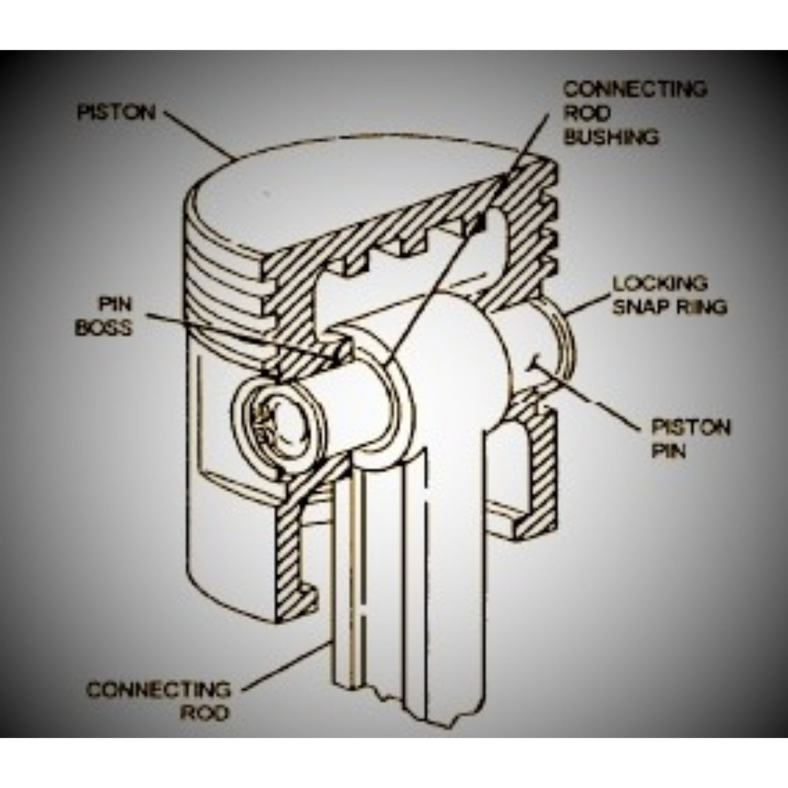
A gudgeon pin, which is also known as a wrist pin, is an important component of an internal combustion engine ( IC ). It establishes a link between the connecting rod and the piston. Gudgeon pins are also useful with connecting rods, wheels, and cranks.

Gudgeon Pin (Piston Pin)

This pin is located in a sliding crosshead that is usually connected to the piston via a rod in most engine arrangements, including steam-powered engines, large stationary and/or marine engines.

This pin is a forged small hollow rod that is typically made of a high-strength steel alloy. Pin design is difficult, particularly in the case of small, high-revving automotive engines. Let’s take a look at how the piston pin works.

Piston pin is made up of ( materials )

The gudgeon Pin is made of steel with a hard, polished surface of the bearing. It can be fitted to the skirt or free to float and rotate, to limit axial movement.

Lubrication of piston pin

A single sleeve bearing bush is pushed into an eye at the end of the connecting rod. During the induction stroke of the four stroke cycle, the piston load is reversed and this enables oil to spread over the lowered surface of the bearing.

Gudgeon Pin (Piston Pin)

The supply of oil in the engine is produced to the bottom by means of oil holes in the crankshaft and thus through the connecting rod.

A non return valve may be fitted in the foot of this connecting rod to prevent back -flow of oil under gravitational force at the bottom of each stroke.

Where is gudgeon pin located ?

It can be fitted to the skirt of the piston and free to float and rotate, to limit axial movement.

The gudgeon-pin must be positioned relative to the piston so that it does not rub against or damage the cylinder.

Functions of Gudgeon Pin

The gudgeon pin (wrist pin, or piston pin ) connects the piston to the connecting rod and serves as a bearing for the connecting rod to pivot on as the piston moves.

Simply, it used to connect the piston to the connecting rod.

Q) What is the function of the piston pin?

a) To connect the piston to the crankshaft
b) To connect the piston to the piston head
c) To connect cam to the piston
d) To connect the piston to the connecting rod

Answer: d
Explanation: The major function of the piston pin is to connect the piston to the connecting rod. The piston pin is also called a gudgeon pin or wrist pin.

Constructions of Gudgeon Pin

The construction of gudgeon pin is usually a forged short hollow or solid rod made of a high strength and hardness steel alloy that can be physically separated from both the connecting rod and the piston or crosshead.

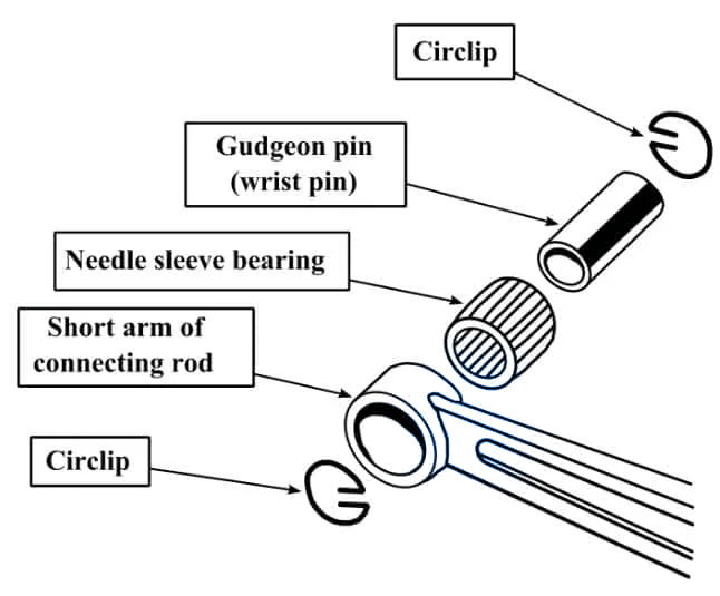
This pin’s ends are chamfered. This pin is held in place in the piston by a circular saw, and it is surrounded from the middle by the connecting rod’s small-bore end.

How gudgeon pin is designed

Designing a gudgeon pin is a quite challenging. The device used must be small and lightweight in order to not add unnecessary weight to the vehicle while also providing a comfortable fit to the often cramped quarters of the engine compartment.

It must also be strong and made of a metal that can withstand a lot of abuse. However, some manufacturers use rare metals to produce the gudgeon pins, whereas others rely on regular stainless steel that is forged under carefully controlled conditions.

The gudgeon pin is typically installed in a semi-floating or fully floating configuration, depending on the engine design. It is discovered acting as a bearing for the connecting rod, allowing rotational movement whenever the engine is running. Specialized versions are created for applications such as car racing, where engine components must be especially strong due to the engine’s high performance, which creates some unique demands.

When engines are inspected, which includes oil changes, tune-ups, and various other routine visits to the mechanic, it shows obvious signs of wear or tear on the engine’s components. If a problem is discovered within one of the components, such as a gudgeon pin, it is simple to replace. This could also indicate that there is an underlying issue with the engine that needs to be addressed properly.

It is critical to take engine problems seriously because ignoring them can lead to catastrophic failures of components or the engine itself. It is noted that the repairs are quite expensive, but it is also noted that it is less expensive to fix a problem than to wait for something else to break and incur the double expense.

Working of Gudgeon Pin

The engine’s development was quite rapid, and its performance improved significantly, resulting in a high demand for engine parts. The important parts of the engine, such as the piston, ensure the cyclic gas pressure and the inertial forces at work. However, the working conditions can be responsible for causing fatigue damage to the piston, such as a seat crack in the piston pin.

Previous research indicates that the highest stress is found on the top end of the piston pin seat, where stress concentration is one of the primary causes of fatigue failure. This is the reason that the piston’s working environment has become more complicated; on the one hand, the FEA for the piston has become more difficult.

Working of Gudgeon Pin (Piston Pin)

The gudgeon pin serves as a turning pair between the small end of the connecting rod and the piston. This can also turn the relative to the connecting rod, the piston bore, or both. The Gudgeon pin must have a sliding fit with both to cause seizure. Furthermore, because the Gudgeon pin is either a hollow or a solid steel cylinder with a length roughly five times its outer diameter and is subjected to only lateral load from the connecting rod, it should not be stressed beyond its bearing limit.

The piston pin is also used to connect the piston and connecting rods within the internal combustion engine, where the piston pin transfers gas pressure into the connecting rods. The rubbing pair is made up of a piston pin and a piston pin boss, and gas pressure is delivered to the rubbing pair via the piston pin and piston pin boss before the piston pin bends.

Types of piston pin

Design Options of Gudgeon Pin

A gudgeon pin typically comes in two design options. The design of a gudgeon pin is determined by technological and technical effectiveness.

  1. Stationery
  2. Semi floating
  3. Fully Floating


1. Stationary

The stationary pin is secured to the piston on the boss, and the connecting rod slides on the pin. Since all movement is made by the connecting rod, can occur uneven wear on the contact surfaces in this type of installation. Due to this, the use of this type of pin is not typical in diesel engines.

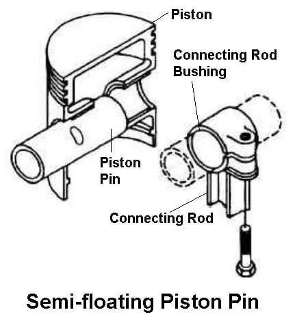
2. Semi- floating

The semi-floating pin is mostly fixed to the piston via an interference that fits with the journal in the piston. The connecting rod, which includes a small end bearing, acts as the sole bearing in this configuration, whereas the small end bearing requires only a bearing surface in this configuration.

This is accomplished through processes such as electroplating, in which the small end bearing journal is electroplated with a suitable metal, or by inserting a sleeve bearing or needle bearing into the eye of the small end, which is provided with an interference fit with an aperture of the small end. It is common practice to replace the bearing sleeve if it becomes severely worn.

Semi- floating - Types Of Piston Pin / Gudgeon Pin

Aside from this configuration, there is a reverse configuration in which the gudgeon pin is fixed to the connecting rod rather than the piston, which is implemented by using an interference installed with the small end eye instead of the gudgeon pin journals in the piston, which functions as a bearing. It has been discovered that this arrangement is quite difficult to manufacture and maintain because both the bearing surfaces and the inserted sleeves complicate the design.

Aside from that, the pin must be precisely set so that the small end eye is in the centre. Because of the thermal expansion conditions, the arrangement was more popular for single-cylinder engines than for multiple-cylinder engines with long cylinder blocks and crankcases, until accurate construction became more popular.

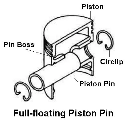
3. Full Floating

Full floating pin configuration includes a bearing surface which is created within the small end eye of the gudgeon pin and the journal in the piston. T Circlips are commonly used to secure the gudgeon pins. There is no such interference found that fits in any case, and the pin floats on the entire bearing surfaces.

Full Floating - Types Of Piston Pin / Gudgeon Pin

A gudgeon pin, also known as a wrist pin, is a critical component in an internal combustion engine. This is in charge of connecting the connecting rod and the piston. The Gudgeon pins are also accompanied by the connecting rod and the wheels or cranks. The term gudgeon pin originated in the United Kingdom, whereas it was known as a wrist pin in the United States and Canada. A variety of manufacturers produce gudgeon pins to replace worn pins.

The engine’s components include a short tube made of forged steel. During the entire running condition of an engine, the gudgeon pin is subjected to a great deal of force. It is discovered that it must successfully withstand thousands of piston firings in a very short period of time. The device is subjected to shearing and bending forces from the connecting rod as well as being subjected to an extremely high environment inside the engine.

Methods of designing of Gudgeon Pin

1.Semi-Floating Pinch-Bolt Small-End-Clamped Gudgeon-Pin

This is a method of fastening the rod to the pin in which the pin’s central portion incorporates a fully or partially formed circumferential groove. When the small end of the connecting rod is centrally aligned to this groove, the movement occurs within the gudgeon-pin and piston bosses. This method allows for the use of a narrow small-end, which increases the width of the rubbing surface within the piston and the gudgeon-pin boss.

2. Semi-Floating Force-Fit Small-End-Clamped Gudgeon-Pin

This arrangement includes the small end of the connecting rod, with its faces polished with emery cloth and heated evenly with an oxyacetylene torch at around 503 to 593 K, until there is a color difference found around the eye, ranging from pale-straw to dark-blue oxide. Following that, the gudgeon-pin is forced through both the piston and the small-end eye is centered. The small end cools the shrink over the pin while also keeping its relative rubbing movement within the pin and the piston bosses.


3. Semi-Floating Piston-Boss-Clamped Gudgeon-Pin

The gudgeon-pin is clamped to one of the piston bosses, and the connecting-small rod’s end is lined up with an interference-fit phosphor-bronze plain bush bearing. This bush aids in the location of the gudgeon-pin and thus provides a low-friction surface for it.

To avoid stripping the thread in the relatively soft alloy, take care when tightening the tapered locking bolt. When the bearing properties of the piston material are not suitable for continuous oscillatory rubbing or are not suitable as heavy-duty, this method is used.

4. Fully Floating Gudgeon-Pin End-Pads

It is recommended that the gudgeon-pins not be directly touched by the cylinder so that the very hard outer edges of the gudgeon-pins do not score the walls once they are allowed to float in their piston bosses.

There are various methods for preventing scuffing, such as spherical end-pads made of aluminum, brass, or bronze that act as a buffer between the walls and the pin. While these operations are ongoing, the gudgeon-pin is found revolving freely at both the small-end in the piston, which has a tendency to improve lubrication.

5. Fully Floating Gudgeon-Pin With Circlip Location

This gudgeon pin is constructed with fully floating Gudgeon pins that provide bearing surface area to the piston-boss bores as well as the small-end bronze bush bearing. Large pivoting angular movement and heavy thrust loads on the piston’s skirt are observed in the engines.

The fully floating pin’s double swivel action reduces the tendency of the gudgeon-pin to slide side by side under heavy-duty conditions. The clips are firmly secured in the internal circumferential grooves formed near the outer end of each gudgeon-pin-boss bore.

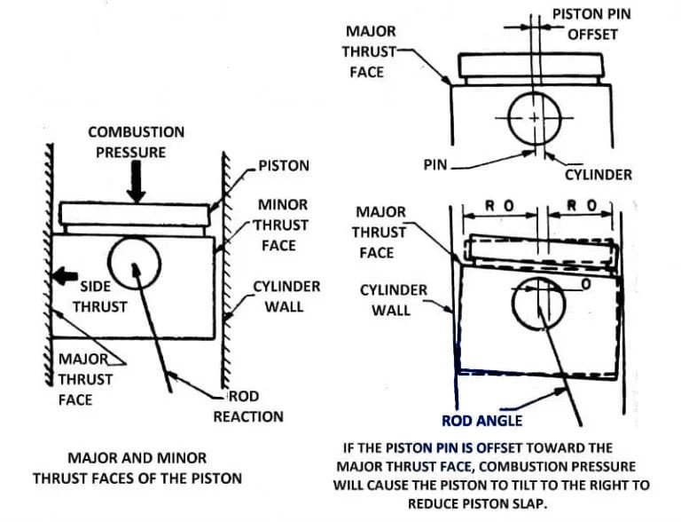
What is piston pin offset ?

This is the piston wrist pin, which is slightly offset from one side of the piston and should not be in the center of the piston. Consider the following two examples to better understand why this occurs:

piston pin offset

When the pin is in the center of the piston, the piston has arrived at TDC or BDC. The rod moves straight up and down in this position, putting a heavy load on it. To make the piston move again, the crank must move past TDC or BDC. This rods generates a significant amount of power and RPM from the engine.

With an offset pin, the piston wrist pin is slightly offset to one side of the piston, preventing the rod from moving straight up and down when the piston is at TDC or BDC. This allows the crank to rotate with less resistance, giving the engine more power and speed.

When the rod reaches the TDC or BDC, the offset pin relieves tension. The rod does not have to hit the piston both up and down. The rod moves in a more arcing motion.

Requirements of gudgeon pin

The following requirements must be met by the pin:

  1. The pin must be strong and flexible enough to withstand the load without being damaged.
  2. To achieve favorable wear behavior, a high surface hardness is required.
  3. For optimum fit with their sliding parts, piston, and connecting rod, these pins must have high surface quality and size accuracy.
  4. To keep inertia forces to a minimum, these pins must be light in weight.
  5. The pin’s rigidity should match the design of the piston to avoid overloading the piston.
  6. Regardless of what is stated above, the pin construction should be as simple and thus economical as possible.

Strength of piston pin

Pressure and tension loads act on the pin’s surface due to the impact of gas and inertial forces during working. As a result, the distribution of which is defined by the deformation of the piston pin bores, piston pins, and short end bore caused by forces.

As a result of the pressure distribution, the pin may be subjected to high bending, elliptical, and shear forces. This is compounded by a torsional load caused by the connecting rod tilting motion.

However, it is neglected due to the limited proportion of the total load. On the other hand, the pin must be as rigid and light as possible.

Stresses And Deformation Experienced By Gudgeon Pin

A Gudgeon pin experiences a high amount of deformations and stress, particularly in a reciprocating compressor used in an air braking system, as predicted scientifically whenever the pin is kept fully floating by surrounding it with lubricating oil and when starved of oil.

Both the analytical approach and the simple bending theory of beams are found in a finite element method, which is commonly used. The inadequacy of the beam approach is highlighted. The results obtained by both of them are precisely compared. The importance of clearance in the piston bore and the small end of the connecting rod, as well as the effectiveness of lubrication, is thoroughly investigated. The safety factor associated with the design of the Gudgeon pin is also closely examined.

Why is a gudgeon pin called a gudgeon pin?

The gudgeon pin is positioned in a sliding crosshead that is directly connected to the piston with a rod in previous versions of engines, such as those that were powered by steam and marine engines.
The word “gudgeon” is derived from the Middle French word “gojoun.”

What is the use of piston pin?

the use of piston pin to connect between the piston and the connecting rod.

Check Out Other Important Topics

IC EngineImportant PDFsBoilersSynergy Maritime ExamNaval ArchMEO Class 4
Interview QuestionsDifference BetweenTypes of PumpsAuxiliary MachinesTypes of ValvesHome

Brushless Alternator Working principle| Advantages, Disadvantages | Applications

This Article is all about What is Brushless Alternator ? Its Working Principle, Parts , Operations , Applications, Advantages and Disadvantages.

brushless alternator working principle

What is a Brushless Alternator ?

A Brushless Alternator is an alternator, which is used for generating the mechanical energy into electrical energy by using the two rotors fitted end to end on same shaft and transferring the induced electricity without Brushes and the slip rings.

or, we can defined as, it is an alternator which do not uses the brushes and the slip rings and consists of two alternator, main excitor and small exciter alternator which is fitted on the same shaft of main alternator with the help of the bridge rectifier.

Constructions of Brushless alternator

  1. .Stator Body
  2. Rotor assembly
  3. Bridge Rectifier

1. Stator Body :- The stator body housing includes main stator and the excitor stator at end of stator body.

2.Rotor body :- Rotor body consists of the main rotors and exciter rotor at end.

3.Bridge rectifier :- It is fitted at end of excitor rotor which is responsible for eliminating Brush and slip rings.

A brushless alternator mainly consists of two parts :-

  1. Main alternator and
  2. Excitor alternator

A Brushless alternator is made up of two alternators that are built end-to-end on a single shaft. Smaller brushless alternators may appear to be a single unit, but the two parts are easily distinguishable on larger models. The main alternator is the larger of the two sections, and the exciter is the smaller. The exciter contains stationary field coils as well as a rotating armature (power coils). The primary alternator employs the inverse configuration, with a rotating field and a stationary armature.

1.Main alternator

The main alternator which has a rotating field and a stationary armature (power generation windings). This is the part that can be confusing, so keep in mind that in this case, the armature is the stator, not the rotor.
The high current output does not have to pass through brushes and slip rings because the armature is in the stationary portion of the alternator. Although the electrical design is more complicated, it results in a very reliable alternator because the only parts subject to wear are the bearings.

2.Excitor alternator

The exciter field coils are located on the stator, while the armature is located on the rotor. The exciter armature’s alternating current output is fed through a series of diodes mounted on the rotor to produce a direct current voltage. This is fed directly to the main alternator’s field coils, which are also located on the rotor. Brushes and slip rings are not required to supply current to the rotating field coils in this configuration. In contrast, a simple automotive alternator uses brushes and slip rings to supply current to the rotating field.

Basic terminology of Alternator

stator – The stator is the stationary component of a motor or alternator, and

rotor :-the rotor is the rotating component.

Magnetic field :- The coils of wire used to generate a magnetic field are referred to as the field, and

Armature :- the coils that generate power are referred to as the armature.
This can be perplexing because most people associate the armature with the rotor. Traditionally, the armature was located on the rotor, but this is not always the case. The two terms are not interchangeable. In a typical automotive alternator, for example, the field is on the rotor and the armature is on the stator. The mechanical configuration consists of a rotor and a stator.

This is very confusing because most people associate the armature with the rotor. Traditionally, the armature was located on the rotor, but this is not always the case. The two terms are not interchangeable. In a typical automotive alternator, for example, the field is on the rotor and the armature is on the stator. The mechanical configuration consists of a rotor and a stator.

Basic working theory of alternator

A magnetic field is created when an electric current is passed through a wire coil (an electromagnet).
When a magnetic field is moved through a wire coil, a voltage is induced in the wire. When the electrons have somewhere to go, such as a battery or other load, the induced voltage becomes a current. Both of these processes occur in alternators, motors, generators, or dynamos.

When a wire coil is moved through a magnetic field, voltage or emf is produced. It makes no difference whether the coil or the magnetic field is moving. Depending on mechanical, electrical, and other objectives, either configuration works equally well and can be used separately or in combination. The old direct current (DC) generators (dynamos) had a stationary field and a rotating armature.
Alternators in automobiles use the opposite configuration, with a rotating field and a stationary armature. Both configurations are used in a brushless alternator in the same machine.

Working principle of Brushless alternator

Alternator works on the principle of faraday’s law of electromagnetic induction.

Brushless alternator Working

We understand the construction of working now let us know about working. There is a residual magnetism attach to the exciter stator. Now when main rotor starts rotating, excitor stator also rotates. Due to faradays law of electromagnetic induction ac current is produced in coils of rotor excitor ( excitor coil ).

Now this ac current is used for exciting. This AC current is passed through bridge rectifier converted into DC. This Dc supply is given to the main rotor. This Dc current produced magnetic field.

Due to rotation of main rotor, Flux of magnetic field cut and AC Current generated in the Coil of\ Stationary main stator. This DC output is used for different applications. Thus, we understand here that how brushless alternator work.

AVR

The another main components of brushless alternator is AVR, It is called automatic voltage regulator. It is used for maintaining constant voltage. In Many diagrams in parts and components and explanations will use the term “AVR” without explaining what it is. Automatic Voltage Regulator (AVR) is an abbreviation for Automatic Voltage Regulator. An AVR performs the same function as a car’s “voltage regulator” or a home power system’s “regulator” or “controller.”

Advantages of Brushless alternator

  1. Not use of Brushes and Slip rings
  2. less maintenance.
  3. The output power of this alternator is more than brushed alternator.

Disadvantages

  1. Initial cost is higher than brushed alternator.
  2. Required expert person to do maintenance.

Application Of brushless alternator

  1. It is used in the wind turbine.
  2. In the train
  3. It is used only in the Case of Alternating current.

Check Out Other Important Topics

( FAQ ) Frequently Asked Questions

Why it is called brushless alternator?

Because there is no use of Brush.

IC EngineImportant PDFsBoilersSynergy Maritime ExamNaval ArchMEO Class 4
Interview QuestionsDifference BetweenTypes of PumpsAuxiliary MachinesTypes of ValvesHome

What is Fresh water generator in ship | Working Principle , Diagram and Uses |

In this article, I am going to discuss about an equipment called Fresh water Generator which is used onboard to produce fresh water on ships. We will discuss it’s working principle, types, how it operates and it’s troubleshooting.

If you any doubt or any problems related this Topic. You are at right place. After reading this Article on this topic, I am damn sure you will not have any Doubts remaining.

In this Article, you will learn :-


What is Fresh Water Generator ?

A Fresh water generator is a Device which is used on ship for production of fresh water from ocean water for domestic and auxiliary functions , which is a vital demand aboard ships.

A considerable quantity of H2O is consumed in a ship.

The crew consumes an average 100 liter/head/day. In a steam ship (a ship whose main propulsion unit is a turbine or a ship which could be a giant tanker with turbine-driven oil pumps) the boiler consumption may be as high as thirty tons per day.

The equipment used on board to generate freshwater from seawater is known as a freshwater generator.

It is used to produce fresh water onboard for drinking,cooking, washing etc.

How pure Water produced on ship ?

Pure water produced on ship ships generally using two principles or Method ; either

  1. Distillation or
  2. Reverse Osmosis.

Reverse osmosis is normally used in passenger ships where large quantities of water is consumed .

Here I am trying to illustrate the working principle of the freshwater generator that works on the basis of the distillation principle that is very common in cargo ships.

Distillation Systems

Fresh water from sea on ship is produced mainly by Distillation process.

What is Distillation ?

  • Distillation is the method of production of pure water from sea water by evaporating and re condensing .

Distilled water is made as a results of evaporating ocean water either by a boiling or a flash process.

This evaporation enables the reduction of the 3200 parts per million of dissolved solids in sea water down-to the one or two percent in distilled water.


Boiling process

This type of evaporator boils sea water at a saturation temperature corresponding to the evaporator pressure and is known as a boiling evaporator.

In a boiling Evaporator, water is maintained continuously at its saturation temperature-in other words, Latent heat is added.

While in the flash evaporator, sensible heat is supplied.

  • Submerged tube type- Boiling Evaporator or tube type
  • Boiling Process Evaporator ( low pressure evaporator ) Alfa laval or plate type :-

This both type of generator discuss below in details.

Suggested Read: Oily Water Separator


Flash Process (Flash Evaporator )

  • This type of evaporator heats the water in one compartment before it is released into a second compartment in which the pressure is substantially lower, causing some of the water to flash into vapour .
  • This type of evaporator is known as flash evaporator .
  • In flash evaporator, sensible heat is supplied.

Types /classification

On the basis of of Working Principle ,it is classified into

  1. Distillate Type
  2. Reverse Osmosis
  • Distillation is cheaper and efficient for less quantity, but RO is expensive and used for production in a large quantity.
  • RO is used on a passenger ship, where a large amount of water is consumed.

  1. Distillation = (Evaporation + Condensation)
  2. Reverse Osmosis = (Semi permeable membrane – filter)

Distillate type is again classified based on the evaporator and condenser structure, i.e

  1. Plate type and
  2. Tube type fresh water generator
  • Tube type ,also known as the submerged type, because the steam coils are submerged.
  • Sometimes it is known as Boiling FWG.


Main or Various type of fresh water generator which are mainly used on ships are :

  1. Submerged Tube Type
  2. Plate Type
  3. Reverse Osmosis Plant

Suggested Read: Steering gear


The main body of a fresh water generator on the ship consists of

  1. Heat Exchanger,
  2. Distillate pump
  3. ejector pump,
  4. air brine eductor
  5. Salinometer
  6. demisters or mesh separator,

1.Heat exchanger

  • Evaporator :- It is used to boil off the sea water at lower temperature with the help of vacuum created inside the fresh water generator shell.
  • Condenser: It use s the sea water to cool down; and condense the steam to achieve distilled water

2.Fresh Water Pump / Distillate pump

  • It is used to supply the generated fresh water to ship’s fresh water tank by taking the suction from fresh water generator.

Normal rated capacity -3m^3/hr

3.Ejector pump

  • It is used to supply pressurised water to the eductor for creating vacuum.It also supplies cooling water to condenser(to cool the fresh water vapours)

Rated capacity–20-30m^3/hr

Pressure- 3-6 bar

4.Air brine eductor:

  • It is used to to remove accumulated brine and salts deposits from the generator and create necessary vacuum.

5.Salinometer:

  • It is connected to the distillate output just before the solenoid operated three way valve. It is used for measuring the ppm of fresh water produced which is generally (1-2ppm)

The salinometer works on the simple principle that pure water does not conduct electricity; and its conductivity increases with increased dissolved impurities and salts.

Suggested Read: Purifier


What is demisters in Fresh Water generator ?

6. Demisters:

  • This is used to separate sea water droplet from the steam vapour.
  • A demisters is a thickened layer of mesh structure; fitted in between the evaporator and the condenser element.
  • A demisters can be made of nickel, monel metals, copper, stainless steel and synthetic fibers; such as Polypropylene and PVC.
  • Typically; demisters made of monel metal are used for the generation of fresh water.
  • when the water evaporates it carry over some fine little molecules of water along with the rising steam.
  • When the source of such water is sea; it can considerably increase the salinity of output water.

So to maintain salinity as low as 5 to 15 ppm; we use demisters which restrict the passage of mist and pass dry steam.

How Fresh Water Generator Works ?

Working Principle

  • The basic principle of all low-pressure freshwater generators is that the boiling point of the water can be reduced by reducing the pressure of the surrounding atmosphere.
  • Water can be boiled at low temperatures by maintaining a low pressure, say 50 degrees Celsius.The heat source for the freshwater generator could be waste heat rejected by main engine jacket cooling water.
  • Hence,boiling can take place at about 40 to 60 degrees Celsius by using energy from a heating coil and by reducing pressure in the evaporator shell.
  • This type of single-effect plant is designed to provide a better economy than obsolete boiling evaporators.

Suggested Read: What are the uses of Filter ?


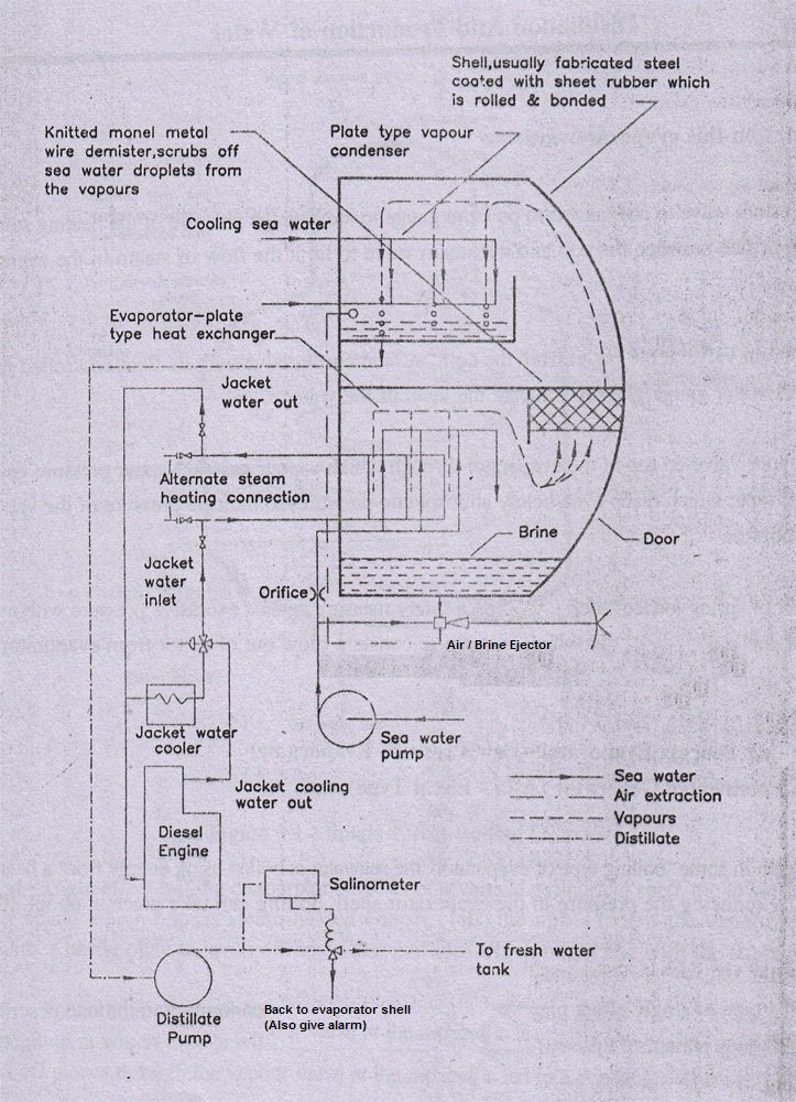
Plate Type Fresh water generator ( Alfa – level Type ) Working

  • If the condenser and evaporator Heat exchangers of a fresh water generator is composed of plates then that type of freshwater generator is called Plate type freshwater generator.
  • The main components are condenser and evaporator heat exchangers, brine air ejectors, seawater pumps, distillate pumps, salinometer, demister, water flow meters, etc.

Below You can see the line diagram.

Fresh Water Generator

Fig :- Plate Type ( Alfa – Lavel Type )

  • Fresh water generator uses heat from main engine jacket cooling system which often cooling the engine passes through evaporator to evaporate the sea water feed into it.
  • But the jacket cooling water temperatures available is about 70-80 degree celcius,whereas boiling of water is 100 degree Celsius at 1 atm.
  • so in order to evaporate sea water at 70 degree Celsius we need to reduce pressure.
  • This is done by creating vacuum inside chamber si that sea water get evaporated below 100 degree celcius and also vacuum helps to evaporate easily.
  • This vaccum is created by air or brine ejector.
  • Now,the evaporated sea water passes through demisters which scrubs off sea water droplets from water vapour.
  • Unevaporated water/ particles is discharged as brine (by means of a combined air / brine ejector).
  • This vapour passes through the condenser which condense the vapour and get collected at the bottom which is transferred to fresh water tank ,where it is passed through salinometer and controlled by three way solenoid valve.
  • The feed rate to the evaporator is fixed at the feed inlet to the evaporator by the orifice plate throughout the entire process.
  • If the salt content of the produced water is high, the solenoid valve diverts the freshwater to the shell side of the freshwater generator and emits an alarm signal.
The solenoid controlled dump valve diverts the flow back to the shell in case of fresh water salinity exceeding a predetermined value (maximum usually 10 ppm).
This prevent contamination of the made water.Excess salinity caused by so many factors including leakage of seawater at condenser or priming of evaporator or malfunctioning of demister, or many other reasons.In FWG,What cannot be condensed at the condenser Is called ‘incondensable gasses’ such as air and these gases are continuously ejected out by air/brineejector.This way, the fresh water generator shell is kept at high vacuum, which is a must to boil water at low temperatures.Suggested Read:

Tube Type Fresh Water Generator

  • Tube type FWG also, known as the submerged type, because the steam coils are submerged.
  • Sometimes it is known as Boiling FWG.
  • The working and principle of the freshwater type tube generator is the same as the plate type fwg.
  • Only difference in instead of plates, condenser and evaporators are tubes.

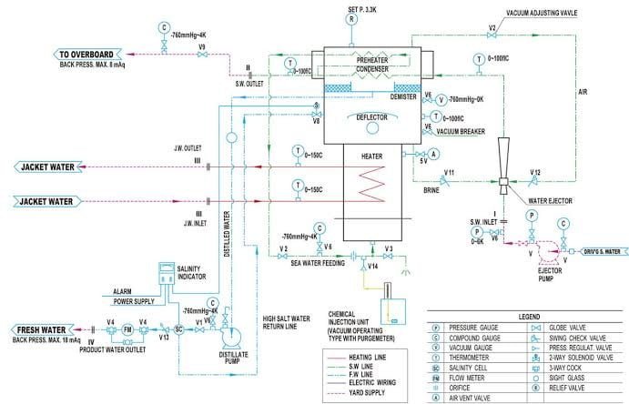
A typical freshwater generator tube-type line diagram is given below..

  • The submerged tube type fresh water generator uses heat from the main engine jacket cooling water to produce water drinkable,by evaporating seawater due to high vacuum, which allows the feed water to evaporate at a comparatively low temperature.Steam can also be used as a source of heat instead of the main engine jacket cooling water.
  • This type of freshwater generator is based on two sets of shell and tube heat exchangers, one act as an evaporator or heater and the another act as a condenser.
  • The combined air / brine ejector creates vacuum condition in the evaporator chamber by driving sea water through the air / brine ejector and sea water supplied by the ejector pump to be delivered to the ejector for taking out the brine (concentrated seawater) and air.
  • The temperature of the feed water in the evaporator chamber is about 50 degrees Celsius. The rate of supply of water to the evaporator is fixed by an orifice fitted at the feed inlet.
  • Due to the vacuum condition inside the evaporator, the feed water evaporates at this temperature.The water spray and the droplets are partly removed from the vapor by the deflector mounted on the top of the evaporator and partly by the demister.
  • The water droplets, which are separated, fall back into the brine, which is extracted by the water ejector.
  • The desalted vapor, which passes through the demister, will come into contact with the condenser, where it will be condensed by incoming cold sea water.
  • The distilled water is then removed by an integral freshwater pump (distillate pump) and controlled by a salinometer and a solenoid valve.
  • If the salt content of the water generated is high, the solenoid valve transfers the freshwater to the freshwater generator shell side and gives an alarm signal.
  • To get a better suction head, the distillate pump is placed in the freshwater generator plant at the lowest possible location.This is because the shell of the freshwater generator is at a lower pressure.

With the height of liquid column in the suction line, the distillate pump gets maximum net positive suction head.

Thermometers are installed to control the seawater to the condenser and the cooling cooling water to the evaporator .These thermometers did the work of controlling of both heating and cooling of these units.

The salinometer or salinity indicator is connected to the remote alarm, so that at the ship’s engine control room, very high salinity is immediately registered.

What are Safety device fitted on Fresh Water generator ?

  • relief valve
  • vaccum gauge
  • vent cock
  • thermometer

What are faults in fresh water generator

What happens when there is fault in FWG ?

  • Faults in the freshwater generator reduce the performance of the system, reducing the quality and quantity of freshwater produced on ships.
  • These irregularities must be identified and corrected immediately to ensure that the optimum performance of the freshwater generator is achieved.

Faults in FWG are :-

1.Loss of Vacuum or Over-pressure of Shell

What reasons may there be for vaccum losses in a fresh water generator?


The shell pressure of the freshwater generator increases and the rate of freshwater produced decreases.

The reasons are:

a) Air leaks into the evaporator shell in large quantities and air ejector cannot cope.

b) The cooling water flow through the condenser is reduced or cooling water temperature is high.

This cause saturation temperature and hence saturation pressure within the condenser to rise.

c) Malfunctioning of the air ejector.

d) Flow rate of the heating medium increased and excess water vapour produced.

Since this excess vapour can not be condensed, the pressure of the shell increases or the vacuum drops.

2.Salt Water Carry Over

During the operation of the freshwater generator salt water can be carried over in large quantities.

This is called priming.

General reasons of the priming are:

a) Level of salt water inside the shell is high.

When water level is high agitation due to boiling occurs and salt water may carry over along with the vapours.

b) When there is a high level of water agitation due to boiling and salt water may be carried along with the vapours.

c) Rate of evaporation increased.

3.Gradual Increase in Level of Brine

A constant level of brine must be maintained in the shell for the satisfactory operation of the freshwater generator.

Brine is the concentrated water of the sea after the release of water vapours.

This brine is gradually extracted from the shell. Typically, this is obtained by the combined air-brine ejector.

It extracts air as well as brine from the shell of fwg.

Any fault with the ejector or the brine extraction pump (in some models) causes the brine level to increase.

4.Increase in Salinity of Freshwater

Possible causes are:

a) Brine level inside shell too high.

b) Leaking condenser tubes or plates.

c) Operation of evaporator near shore with contaminated feed water.

d) Shell temperature and pressure too low.

e) Increased solubility of CO2 generated from the salt water due to reduced sea water temperature.

This dissolved CO2 makes water acidic and conductivity of water increases.

Salinometer therefore shows increased salinity, which is a measure of conductivity and non-salt presence.

How Scale Formation Occurs in Fresh Water Generator

Fresh water generator performance reduces with scale formation because it causes reduction in heat transfer efficiency.

In FWG three scales are normally found these are :-

Calcium Carbonate, CaCO3
Magnesium Hydroxide, Mg(OH)2
Calcium Sulphate, CaSO4

The formation of calcium carbonate and magnesium hydroxide depends mainly on the operating temperature.And,the formation of calcium sulphate depends mainly on the density of the contents of the evaporator or the brine.The reaction takes place when the sea water is heated:

Ca(HCO3)2 ————> Ca + 2HCO3

2HCO3 ————> CO3 + H2O + CO2

If it is heated up to approx. 80 degrees Celsius

CO3 + Ca ————> CaCO3

If it is heated above 80 degrees Celsius

CO3 + H2O ————> HCO3 + OH

Mg + 2OH ————> Mg(OH)2

Hence, if the sea water is heated to a temperature below 80 degrees Celsius in the freshwater generator, the calcium carbonate scale will predominate.
The magnesium hydroxide scale is deposited when sea water is heated above 80 degrees Celsius.

If the evaporator content density is greater than 96000 ppm, the calcium sulphate scales are formed.But, brine density of FWG is normally 80000 ppm and less.Hence, the formation of scales due to calcium sulphate is not a problem.

That’s why It is recommended that the freshwater generator be operated at its rated capacity, not more.More water production than the rated capacity means a higher concentration of brine and a more formation of scale.Similarly higher shell temperatures result in hard scale formation that will be hard to remove.All of these together will dramatically reduce efficiency of plant.

How to minimize scale formation

The formation of a scale in a freshwater generator can be controlled and minimized by continuous treatment of chemical.

Marine engineers prefer polysulphate compounds (such as sodium polysulphate) with anti-foam, which are commonly used on ships.

These chemicals reduce the scale formation of calcium carbonate and possibility of foaming.

The compound is

  • non toxic,
  • no-acidic,

and can be used in fresh water generator producing water for drinking purposes.

It will be continuously feed via a metering pump or by gravity to the feed line.

The quantity of chemical to be dosed depends on the capacity of the fresh water produced.

The main thing is that,this chemical doses is effective only on low pressure fresh water generators.

The temperature of the sea-water is less than 90 degrees.

In order to maintain performance of Fresh water generator chemical treatment to be religiously carried out.

What are the causes for low production of Fresh Water ?

Reasons of Low Production are following :-

  1. Ships draft is less.
  2. level of brine is too high.
  3. Filter before ejector pump is dirty .
  4. Faulty ejector pump- not developing enough pressure
  5. Faulty Ejector nozzle/ nozzle chocked
  6. Incorrect feed
  7. scale formation in evaporator
  8. shell temperature is too high
  9. scale formation in condenser
  10. condenser cooling water flow is reduced
  11. Condenser cooling water temp. too high
  12. Incorrect assembly of plates
  13. Leakage in plant like from pressure gauge, vent, distillate pump seal etc.
  14. Distillate pump faulty
  15. Faulty flow meter
  16. Faulty solenoid valve

How Do I Start a fresh water generator ?

Starting of fresh water generator

Starting the Fresh Water Generator,few important point to be noted:-

We need to check before starting the fresh water generator that the ship is not in congested water, canals and is 20 nautical miles away from the shore.This is done because the effluents from factories and sewage are discharged into the sea near the shore which can get into the FWG.

Check whether the engine runs above 50 rpm, which is because the temperature of the jacket water at low rpm is around 60 degrees and is not sufficient for water evaporation.

  1. Check the drain valve is in close position,Which is present at the bottom of the generator.
  2. Now open the sea water pump’s suction and discharge valves which provide water for evaporation, cooling, and to the eductor for vacuum formation.
  3. Open the seawater discharge valve through which the water is sent back to the sea after , circulating inside the freshwater generator.
  4. Close the vacuum valve, which is situated on top of the generator.
  5. Now, we should Start the sea-water pump and check the pump pressure. In general, the pressure is 3-4 bar.
  6. Wait until the vacuum builds up. Vacuum should be at least 90 percent, which can be clearly seen on the generator gauge ,situated on FWG . The time taken for vacuum generation is usually around 10 minutes.
  7. When vacuum is achieved, open the valve for the treatment of feed water, this is designed to prevent the formation of a scale within the plates.
  8. Now open the inlet and outlet valves of hot water (jacket water), slowly to about half.Always,First open the outlet valve and then the inlet valve. Slowly start increasing the opening of the valves to full opening.
  9. Now we can see that the boiling temperature starts to rise and the vacuum starts to fall.
  10. The vacuum drops to about 85 percent, which is an indication that evaporation begins.
  11. Open the valve for drain from the fresh water pump.
  12. Switch ON to the salinometer if it has to be started manually. Generally, it’s on the auto start mode.
  13. Now start the fresh water pump and test the water that comes out of the drain.
  14. When fresh water starts generating, it can be seen that the boiling temperature drops slightly again and that the vacuum goes back to normal value.
  15. Check that the water, which coming out of the salinometer is not salty and also check the reading of the salinometer.This is done to see whether the salinometer is working properly or not, and to avoid contamination of the entire fresh water with salt water.Salinometer values are kept below 10ppm.
  16. Open valve for tank from the pump and close drain valve after testing the taste of the water coming out of the salinometer.


Fresh water Generator Stopping Procedure

It is desirable to stop the fresh-water generator as ship approaches port, shallow water, etc.This is because the seawater may contain harmful bacteria that can enter into the produced freshwater.The operation of freshwater should be carried out in consultation with the bridge watchkeeper.

Following, procedure to stop the fresh water generator can be adopted.

  1. Open the bypass valve , slowly for main engine jacket cooling water.
  2. Ensure that the cooling water temperature of the main engine jacket is within normal limits.
  3. Close inlet and outlet valves of jacket cooling water for the freshwater generator respectively.
  4. Close the feed water chemical dosing valve.
  5. Stop the distillate pump and shut down the discharge valve.
  6. Switch off the salino meter.
  7. Close the filling valve of the freshwater tanks.
  8. Wait for the temperature of the evaporator shell to drop below 50 deg celcius.
  9. Close the evaporator feed-water valve.
  10. Stop the pump ejector. Shut down overboard valve of fresh water generator.
  11. Open the vacuum breaker valve so that the side pressure of the shell is equal to the atmospheric pressure.
  12. Open the evaporator drain valve to drain all the seawater from the freshwater generator.

Precautions for Operation of Fresh water Generator

  1. The pressure of seawater at the inlet of air ejector must be 3 bar or more.
  2. The ejector outlet pressure should not exceed 0.8 bar.
  3. The distillate pump of fresh water generator never start in dry condition.
  4. To prevent thermal shock to the main engine, operate the jacket cooling water valves slowly to the fresh water generator.
  5. Feed water to be supplied to cool down the evaporator for a few minute before stopping.
  6. Never open the evaporator drain valve before the vacuum breaker is opened. Otherwise, the atmospheric pressure causes seawater to hit the deflector insiders.

In this Article,I have written answers to all Questions arises on this Topic which I have learned from my faculty or from books.

Anything I missed ? Please write it down in the comment section and don’t forget to share it, because sharing is caring.

Wikipedia

Follow me on Twitter :- Click Here

Check Out Other Important Topics

Read More: What is the Function of Air Compressor ?

Read Here : Frequently Asked Questions in Interview

Frequently Asked Questions ( FAQ )

What are the two types of fresh water generator?

Two Types are :-
1. Submerged tube type
2. Plate type

Method of generating Fresh water on Ship

1. Fresh Water Generator…
2. Reverse Osmosis

What is the importance of fresh water generator?

It is An important part on Ship because it is used for generating fresh water. Fresh water generated is used for drinking, cooking, washing, and even powering important machinery that uses fresh water as a cooling medium.

What are the two simple working principle of fresh water generator?

1. distillation and
2. effect of pressure on boiling point.

What is condenser in fresh water generator?

The clean vapour is condensed after it has been filtered by being cooled again in the condenser.

What happens when vacuum reaches 100% in fresh water generator?

Boiling rate is very high , Salinity become high because of agitation. So,open the vacuum breaker to maintain 93% vacuum.

How does a fresh water generator work?

distillation process.

IC EngineImportant PDFsBoilersSynergy Maritime ExamNaval ArchMEO Class 4
Interview QuestionsDifference BetweenTypes of PumpsAuxiliary MachinesTypes of ValvesHome

Procedure of piston removal of 2 stroke and 4 stroke engine

Piston removal of 2 stroke and 4 stroke engine ?

To remove piston we have to prepare some documents and preparations related engine.

Always wear Protection protective equipment.

piston removal of 4 stroke engine

if you read the post Decarb of auxiliary engine, you definitely know how to remove piston. if you have not read then here written below the full information and process to remove piston. So let us start.

First tool box meeting and preparations of all the tools required for removal. Risk assasement and tell about the procedure to person involve. Go through manual.

Come to the auxiliary engine platform and start the another generator after with taking proper precautions. Wait for five minute and check all parameter are ok. after that come to ECR and take on load and shut off the generator which need to be work.

Start the priming pump and let it cool down. After half an hour stop the priming pump. Open the indicator valve. Start opening the crankcase door of all unit one by one. After opening let it cools down for some times.

Now let us start the procedure.

shut of all the line

  • Fuel oil inlet and outlet valve
  • jacket water valve
  • sea water valve
  • air starting valve

First remove all the piping system attach to the cylinder head.

  • Air scavenging manifold
  • exhaust manifold
  • fuel pipe
  • jacket water pipe
  • Air starting line

Now open the top cover and side cover of cylinder head.

  1. Start dismantling rocker arm bridge, remove the push rod.
  2. open the tightening nut of fuel injector and remove support. To remove fuel injector there is a special tool looks like crow bar in daihatsu diesl engine. If that tools is not available then we can remove fuel injector with the help of crow bar.
  3. Finally remove the cylinder head.

Now main work start

Clean the surface of piston and put some water in the hole where lifting tools fit.

Take piston on TDC. Put eye bolt or lifting tools on piston.

now open the nut of crank pin or connecting bottom end bearing.

Suggested :- Are you inetrested in knowing the procedure how to remove bottom end bearing and take its clearance.

Depending upon the engine, to remove nut of crank pin some engine require torque spanner and some engine require hydraulic tools.

In daihatsu diesel engine i used torque spanner to open nut.

For hydraulically fitted nut, put the hydraulic nut on bolt and tighten it. After tightening it loosen it by one turn in opposite directions.

purge the hydraulic hose and put the hose on hydraulic nut. Start increasing pressure on it. When pressure reaches upto 60 bar, Stop increasing the pressure. With the help of tommy bar open the nut. Release pressure and remove hydraulic hose.

Remove nut. With help of pulley ;ift the piston and take it on workshop for overhauling.

Piston removal of 2 stroke engine

Inform the company and take imobilasation certificate and inform port that main engine not ready for this hours. Risk assasement with person involve and go through manual. Prepare all tools. Also prepare enclose space entry. Shut the main lube oil pump and proper ventilation of crankacse then enter for removal of nut of foot of piston rod.

Now, shut down the engine and locked the air starting valve. Now open the indicator valve and do not forget to engage the turning gear.

Close the exhaust valve for exhaust valve if your engine is loop or cross type no need.

Now disconnect all the pipe attach with the cylinder head and protect all the openings by covering it with cloth. Close the inlet and outlet of jacket water system and drain jacket water. Fuel valve also closed and disconnect the fuel injection pipes that is high pressure pipes.

Now remove the plastic cap of cylinder head bolt and clean the bolt.

Clean the hydraulic nut and surface near it.

Install the Spacer and then tight hydraulic nut and loosen if by half turn and purge the hose of hydraulic pipe. and connect it to nut and increase pressure. Increase pressure upto 1020 bar. If pressure reaches to 1020 bar then Loose the nut with tommy bar.

Release pressure and remove hydraulic hoses and nut. Now our cylinder head is ready to lift. Put eye bolt on cylinder head. With engine room crane lift slowly. Lift it and put it on Wooden block.

Now remove the Scraper or polishing rings which is fitted in top of liner. Clean the parts of top part of piston crown and liner.

Take the caliberation of cylinder liner. Calliberation taken by template with the help of internal micrometer at port or stbd and fwd or aft. Noted down and compare the wear rate with previous one.

Now with turning gear turn the engine so that piston is at TDC.

Connect hydraulic tenstioning nut and increase pressure upto 1020 bar. Noe piston rod is free. Put distance piece on the footb of piston. This distance piece did the work of pushing gland box and also help in protecting damage of scraper rings.

Open the internal of gland box. Now put lifting tools on piston and lift the piston with the help of engine room crane. Meanwhile cover the stuffing box to protect from dirt. Lower the piston rod on hole provide on the cylinder head platform.

This is all bout removal of piston of 2 stroke engine.

Now we have to clean all the parts of piston. Remove the piston rings with the help of rings extractor . and clean the grooves and take all clearance of piston rings. If it is required to change rings then change it.

Note: – To remove piston we have to open the cylinder head and bottom connecting rod in the case of 4 stroke and piston foot in the case of 2 stroke.

This is all about removal of piston procedure. But if you have to remove the stuffing box or doing overhaul then you have to remove piston.

If you like our content do not forget to share . Thank you.

Soot Blowing in Boiler through air or steam | Operations and how it is done |

Soot Blowing in Boiler : Soot blowing in a boiler is a maintenance process designed to remove soot and ash deposits that accumulate on the heat transfer surfaces of the boiler, such as tubes and economizers. These deposits can significantly hinder the efficiency of the boiler by acting as insulators, reducing heat transfer, and potentially leading to overheating or even fires if left unchecked.

soot blowing in boiler

What is soot blowing in Boiler?

A soot blowing is a procedure of removing the soot built up on the surface of pipe when hot exhaust gas pass through it. or, we can simply define it as – the process of removal of soot deposits exhaust gas passing tubes with the help of steam or air. It is done by a device name called soot blower.

Suggested Read : Boiler gauge Glass Blow Through procedure

What is the purpose of soot blowing ?

Soot blowing is an essential maintenance procedure used in boilers, especially on ships. Its primary purpose is to remove soot and ash deposits that accumulate on heat transfer surfaces, ensuring optimal thermal efficiency and safe operation. Here are the key points regarding soot blowing:

Purpose of Soot Blowing

  1. Maintain Heat Transfer Efficiency: Soot deposits act as insulators, reducing the effective surface area available for heat transfer. Regular soot blowing helps maintain efficient heat transfer, ensuring that water converts to steam effectively.
  2. Prevent Overheating and Fires: Thick soot layers can lead to overheating of boiler tubes and, in severe cases, can cause fires, especially if the soot becomes wet and lowers its flash point.
  3. Enhance Boiler Efficiency: Regular removal of soot increases boiler efficiency, allowing the system to operate at its designed capacity and reduce fuel consumption.
  4. Reduce Emissions: A cleaner heat exchange surface can lead to more complete combustion of fuel, resulting in lower emissions of pollutants.
  5. Extend Equipment Lifespan: By preventing excessive soot build-up, soot blowing reduces the risk of corrosion and other damage, extending the life of the boiler and associated components.

Note :

  • On Ships: Soot blowing is typically performed using steam in the middle of the ship, where Economizer Gas Bypass (EGB) systems are prevalent. This method effectively dislodges soot from boiler tubes.
  • In Port: When the main engine is not in operation, air is often used for soot blowing in boilers. This method, while effective, may be less efficient than steam.
  • Modern Techniques: Some modern ships utilize chemicals combined with air to enhance soot removal, making the process more efficient and potentially reducing the frequency of mechanical soot blowing.

Regular soot blowing is crucial for the safe and efficient operation of marine boilers and heat exchangers. By removing soot deposits, it helps ensure that the systems function effectively, reducing risks of fire and improving overall operational efficiency.

Soot Blowing Procedure for Economizer through Steam

1.Notify the Bridge: Inform the bridge before starting the soot blowing operation to ensure that all personnel are aware and can monitor the situation.

2.Check Wind Direction: Assess the wind direction to avoid blowing soot towards areas where personnel or equipment may be affected.

3.Verify Boiler Parameters:

    • Steam Pressure: Check the current steam pressure of the boiler.
    • EGB Temperature: Measure the temperature of the Exhaust Gas Boiler (EGB).

    4.Adjust Boiler Pressure:

      • If the boiler pressure is below the required level (ideally around 10 bar), increase the pressure:
        • Increase Firing: Raise the fuel input to boost steam production.
        • Close Steam Lines: Close the steam lines from tanks (e.g., waste oil tanks) to redirect steam for soot blowing.

      5.Initiate Soot Blowing:

        • Once the boiler pressure reaches approximately 10 bar, begin the soot blowing operation.
        • Continue the process until the boiler pressure drops to between 6-7 bar.

        6.Post-Soot Blowing Monitoring:

          • After completing the soot blowing, monitor the following:
            • Steam Pressure Recovery: Ensure that the steam pressure of the boiler gradually increases, indicating improved efficiency.
            • EGB Temperature: Watch for a decrease in the EGB temperature, which suggests effective soot removal.

          Important Notes

          • Pressure Drop Warning: A significant drop in steam pressure may indicate that the feed pump is losing suction from the cascade tank.
          • Temperature Increase Warning: An increase in EGB temperature could signify potential EGB fire, requiring immediate investigation and action.

          By following these steps carefully, the soot blowing process can enhance boiler efficiency and safety while minimizing operational risks.

              Soot Blowing in Boiler through Air

              1.Notify the Bridge: Inform the bridge before starting the operation to ensure safety and awareness.

              2.Check Wind Direction: Assess wind direction to avoid blowing soot towards personnel or sensitive equipment, as this poses a fire hazard.

              3.Raise Boiler Pressure: if necessary, raise the boiler pressure using previously mentioned methods (e.g., increasing fuel firing or adjusting steam lines).

              4.Open the Drain Valve: Open the drain valve on the soot blow pipe and ensure that the drain runs clear of any residual water or condensate.

              5.Open the Soot Blower Valve: Open the soot blower valve to initiate air flow.

              6. Increase Air Supply: Increase the air supply to the boiler by 50% to enhance the effectiveness of soot blowing.

              7. Operate the Steam Valve: Open the steam valve by turning the wheel. Maintain this position for 20-30 seconds to allow for effective soot removal.

              8. Close the Valves: After the designated time, close the steam valve and then close the main soot blower valve.

              9. Final Drain Check: Open the drain valve once more and then close it to ensure that any residual soot or condensate is expelled.

                Important Notes

                • Wind Direction: Always check wind direction prior to commencing soot blowing to minimize fire hazards.
                • Duration: Do not engage in soot blowing for extended periods to avoid potential operational issues or equipment damage.
                • Monitor Conditions: Keep an eye on system parameters during the operation to ensure safe and efficient soot removal.

                By adhering to this procedure, you can effectively manage soot accumulation using air while prioritizing safety and operational integrity.

                Abrasive Jet Machining – Parts, Working Principle, Application

                In this article you will learn about Abrasive Jet Machining, including the working principle, parts, working, applications, advantages and disadvantages.

                Abrasive Jet Machining

                Abrasive Jet Machining is a non traditional method of removing materials by using a focused stream of abrasive grains of Al2O3 or SiC carried by high-pressure gas or air at a high velocity is made to impinge on the work surface through a nozzle of 0.3- to 0.5-mm diameter.

                In other words, Abrasive jet machining is the process of impinging a high-speed stream of abrasive particles onto a work surface via a nozzle with high-pressure gas or air, and metal removal occurs due to erosion caused by high-speed abrasive particles.

                The impact of the particles generates a concentrated force sufficient to perform operations such as cutting; the material is removed by the erosion of work material with abrasive grits at a speed of 150-300m/s. Abrasive grits are applied in a high-velocity gas stream.

                Working Principle of Abrasive Jet Machining

                The working principle of abrasive jet machining is the use of a high-speed stream of abrasive particles carried by a high-pressure gas or air on the work surface via a nozzle.

                The metal is removed due to erosion caused by abrasive particles impacting the work surface at high speeds. With each impact, small bits of material are loosened, exposing a new surface to the jet.

                This process is mainly employed for such machining works which are otherwise difficult, such as thin sections of hard metals and alloys, cutting of material which is sensitive of heat damage, producing intricate holes, deburring, etching, polishing etc.

                Abrasive Jet Machining Parts

                1. Gas Supply

                In the machining system, a gas (nitrogen, CO2, or air) is supplied under a pressure of 2 to 8 kg/cm2 . Oxygen should never be used because it causes a violent chemical reaction with workpiece chips or abrasives. This abrasive and gas mixture is ejected at a high velocity of 150 to 300 m/min from a small nozzle mounted on a fixture.

                2. Filter

                The filter cleans the fuel supply so that dirt and other impurities do not impede the process’s progress.

                3. Pressure Gauge

                The pressure gauge is used to control the compressed air pressure used in abrasive jet machining. as the pressure determines the depth of cut and the amount of force required to cut

                4. Mixing Chamber

                Abrasive powder is fed into the mixing chamber, and the amount of abrasives can be controlled using a vibrator. So that the abrasives and gases are thoroughly mixed in the mixing chamber.

                5. Nozzle

                The nozzle is used to increase the velocity of the fine abrasive jet slurry at the expense of pressure, because we know that lowering the pressure causes the velocity to increase. The jet’s velocity will be between 100 and 300 meters per second.

                The nozzle can be adjusted to achieve the desired angular cutting and the material can be removed by impact erosion.

                Because of the high wear, the nozzle is usually made of tungsten carbide. The nozzle’s diameter is approximately 0.2-0.8mm.

                The nozzle’s material should be corrosion resistant. The nozzle has a circular or rectangular cross-section, and the head can be straight or at a right angle.

                6. Abrasives

                In abrasive jet machining, silicon carbide and aluminum oxide glass beads are used as abrasives. The abrasives’ shapes can be regular or irregular. The abrasives range in size from 10 to 50 microns. The mass flow rate of the abrasives is between 2 and 20 grams per minute.

                The choice of abrasives is determined by the MRR, the type of work material, and the level of machining accuracy required.

                Aluminum oxide (Al2O3) size 12, 20, 50 microns is good for cleaning, cutting, and deburring; Dolomite size 200 mesh is used for Etching and polishing.

                Sodium bicarbonate has a particle size of 27 microns and is used for cleaning, deburring, and cutting soft materials.

                7. Workpiece

                The metal removal rate is determined by the nozzle diameter, the composition of the abrasive gas mixture, the hardness of the abrasive particles and the hardness of the work material, particle size, jet velocity, and the distance of the workpiece from the jet. In cutting glass, a typical material removal rate for abrasive jet machining is 16 mm/min.

                8. Regulator

                The regulator is used for controlling the flow of compressed air flowing through the pipe.

                Working of Abrasive Jet Machining

                In the machining system shown in Fig, a gas (nitrogen, CO2, or air)
                is supplied under a pressure of 2 to 8 kg/cm2 . Oxygen should never be used
                because it causes a violent chemical reaction with workpiece chips or
                abrasives. After filtration and regulation, the gas is passed through a mixing chamber that contains abrasive particles and vibrates at 50 Hz.

                working principle of Abrasive Jet Machining


                From the mixing chamber, the gas, along with the entrained abrasive particles (10–40 µm), passes through a 0.45 mm diameter tungsten carbide nozzle at a speed of 150 to 300 m/s. Aluminum oxide (Al2O3) and silicon
                carbide powders are used for heavy cleaning, cutting, and deburring.

                Magnesium carbonate is recommended for use in light cleaning and etching, while sodium bicarbonate is used for fine cleaning and the cut- ting of soft materials. Commercial-grade powders are not suitable because their sizes are not well classified. They may contain silica dust, which can be a health hazard.

                It is not practical to reuse the abrasive powder because contaminations and worn grit will cause a decline of the machining rate. The abrasive powder feed rate is controlled by the amplitude of vibrations in the mixing chamber. The nozzle standoff distance is 0.81 mm. The relative motion between the workpiece and the nozzle is manually or automatically controlled using cam drives, pantographs, tracer mechanisms, or using computer control according to the cut geometry required.

                Masks of copper, glass, or rubber may be used to concentrate the jet stream of abrasive particles to a confined location on the workpiece. Intricate and precise shapes can be produced by using masks with corresponding contours. Dust removal equipment is incorporated
                to protect the environment.

                Applications of Abrasive Jet Machining

                Lets discuss what is use of abrasive jet machining :

                1. Drilling holes, cutting slots, cleaning hard surfaces, deburring, and polishing

                2. Deburring of cross holes, slots, and threads in small precision parts that require a burr-free finish, such as hydraulic valves, aircraft fuel systems, and medical appliances.

                3. Machining intricate shapes or holes in sensitive, brittle, thin, or difficult-to-machine materials

                4. Insulation stripping and wire cleaning without affecting the conductor

                5. Micro-deburring of hypodermic needles

                6. Frosting glass and trimming of circuit boards, hybrid circuit resistors,
                capacitors, silicon, and gallium.

                7. Removal of films and delicate cleaning of irregular surfaces because
                the abrasive stream is able to follow contours

                8. It is used for abrading and frosting glass, ceramics, and refractories and is less expensive than etching or grinding.

                9. Cleaning of metal layering, such as resistive coating.

                10. Small casting deflashing and parting line trimming on injection molded parts and forgings

                11. It is used to engrave registration numbers on toughened glass used in automobile windows.

                12. Used to clean metallic molds and cavities.

                13. Cleaning surfaces of corrosion, paints, glues, and other contaminants.

                Advantages and Disadvantages of Abrasive Jet Machining

                Advantages

                • Because AJM is a cool machining process, it is best suited for machining brittle and heat-sensitive materials like glass, quartz, sapphire, and ceramics.
                • The process is used for machining super alloys and refractory materials.
                • It is not reactive with any workpiece material.
                • No tool changes are required.
                • Intricate parts of sharp corners can be machined.
                • The machined materials do not experience hardening.
                • No initial hole is required for starting the operation as required by
                  wire EDM.
                • Material utilization is high.
                • It can machine thin materials.
                • A high surface finish can be obtained through this process.

                Disadvantages

                1. The removal rate is slow.

                2. Stray cutting can’t be avoided (low accuracy of ±0.1 mm).

                3. The tapering effect may occur especially when drilling in metals.

                4. The abrasive may get impeded in the work surface.

                5. Suitable dust-collecting systems should be provided.

                6. Soft materials can’t be machined by the process.

                7. Silica dust may be a health hazard.

                8. Ordinary shop air should be filtered to remove moisture and oil.

                9. Process capacity is less due to a low material removal rate.

                10. While machining soft materials, abrasive becomes embedded, reducing the surface finish.

                11. The tapering of the hole caused by the unavoidable variation of an abrasive jet disturbs cutting accuracy.

                12. Because of stray cutting, accuracy is poor.

                13. Because a dust collection system is a basic requirement for preventing atmospheric pollution and health hazards, the additional cost will be present.

                14. The nozzle’s life is limited (300 hours).

                15. Because the sharp edges of abrasive powders wear down and smaller particles can clog the nozzle, they cannot be reused.

                16. A short standoff distance can cause nozzle damage.

                17. Because of the flaring effect of the abrasive jet, the process accuracy is poor.

                18. A taper will be present in deep holes.

                19. AJM The process is harmful to the environment and causes pollution.

                20. Abrasive particles in the air can create a hazardous environment.

                Effect of Grain Size And Flow Rate of Abrasives on Material Removal Rate

                At a given pressure, MRR increases with increasing abrasive flow rate and is determined by abrasive particle size.

                However, after reaching the optimum value, MRR decreases as the abrasive flow rate is increased further.

                This is because the mass flow rate of the gas decreases as the abrasive flow rate increases, and thus the mixing ratio increases, resulting in a decrease in material removal rate due to a decrease in available energy for erosion.

                Effect of Exit Gas Velocity And Abrasive Particle Density:

                The velocity of the carrier gas that transports the abrasive particles varies significantly with the density of the abrasive particles.

                When the internal gas pressure is near twice the pressure at the exit of the nozzle and the abrasive particle density is zero, the exit velocity of gas can be increased to critical velocity.

                Exit velocity will decrease for the same pressure condition if the density of abrasive particles is gradually increased.

                It is because the kinetic energy of the gas is used to move the abrasive particles.

                Effect of Mixing Ratio on Material Removal Rate:

                As the abrasive’s mass flow rate increases, its velocity decreases, reducing the available energy for erosion and, ultimately, the material removal rate.

                Effects of Nozzle Pressure on MRR

                The abrasive flow rate can be increased by increasing the carrier gas flow rate. As the internal gas pressure rises, so does the abrasive mass flow rate, and thus the MRR.

                The rate of material removal increases as the gas pressure rises. The kinetic energy of the abrasive particles is responsible for material removal during the erosion process.

                Why are abrasive particles not reused in Abrasive jet machining?

                Fine abrasive particles entrained in a gas stream are permitted to impact the work surface at high velocity (100–300m/s) to gradually degrade material in the abrasive jet machining (AJM) process. Impact erosion is the mechanism for material removal. The carrier gas transports eroded material in the form of solid small particles and utilized abrasive grits away from the machining zone. Because of the following two reasons, reusing these abrasive particles is not suggested.

                1. Wear debris contaminates abrasives (removed work material).
                2. Abrasives lose their sharp edges, reducing their cutting effectiveness.

                Frequently Asked Questions

                What is use of abrasive jet machining?

                Common applications include cutting heat-sensitive, brittle, thin, or hard materials. It is specifically used to cut intricate shapes or form specific edge shapes.

                Which gas is used in abrasive jet machining?

                Abrasive jet machining creates a jet by mixing gas with abrasive particles. The gas used is known as carrier gas. Air, carbon dioxide, and nitrogen are three of the most commonly used carrier gases. Oxygen is never used as a carrier gas because it can oxidize the work piece’s surface.

                AJM can be used for

                Abrasive jet Machining process can be used for can be used for deburring, cutting, cleaning and for many other heavy duty applications.

                In abrasive jet machining process the abrasive particles should be

                In AJM, generally, the abrasive particles of around 50 μm grit size would impinge on the work material at a velocity of 200 m/s from a nozzle of I.D. of 0.5 mm with a stand-off distance of around 2 mm.

                How is the material removed in Abrasive jet machining?

                In abrasive jet machining, a focused stream of abrasive particles is impinged on the work surface through a nozzle and work material is removed by erosion by high velocity abrasive particles carried by high pressure air or gas. Because the carrier gas acts as a coolant, the cutting process is cool. The high-velocity abrasive stream is created by transferring the pressure energy of the carrier gas or air to its kinetic energy, resulting in a high-velocity jet.

                Abrasive Jet Machining MCQ

                Q. In Abrasive jet machining, work piece material of removed by which of the following means?
                a) Vaporization
                b) Electro plating
                c) Mechanical abrasion
                d) Corrosion
                Answer: c

                Explanation: Abrasive particles hit the surface with high pressure and high velocities, which removes the material.

                Q. Metal removal rate in Abrasive jet machining increases with

                a) Increase in standoff distance but decreases beyond a certain limit
                b) Decrease in abrasive flow rate
                c) Decrease in grain size in grain size of abrasives
                d) None of the mentioned
                Answer: a
                Explanation: MRR is directly proportional to standoff distance up to certain limit. After certain limit, kinetic energy of abrasives starts decreasing.

                Q. Which type of materials can be machined using Abrasive jet machining?
                a) Glass
                b) Ceramics
                c) Hard materials
                d) All of the mentioned

                Answer: d
                Explanation: Materials like ceramics, glass, hard and super hard materials can be machined using Abrasive jet machining.

                Hope you liked this article covering all the aspects of Abrasive Jet Machining covering its working principle, advantages, disadvantages and its application.

                If you liked the article, please share it with your friends and give your feedback in the comment section.

                Check Out Other Important Topics

                Water Jet Machining – Working Principle, Applications, Advantages

                What is Process Planning | Process Planning Steps, Types, Advantages

                What is Cold Working – Methods & Working Processes

                What is Hot Working ? Methods & Processes

                Ultrasonic Machining Process – Parts Working Principle, Advantages

                Forging Operations – Types, Methods, Advantages, MCQs

                Steel Making Process – Complete Overview with Flowchart

                IC EngineImportant PDFsBoilersSynergy Maritime ExamNaval ArchMEO Class 4
                Interview QuestionsDifference BetweenTypes of PumpsAuxiliary MachinesTypes of ValvesHome

                What is COPT & Its Operation, Maintenance & Safety

                COPT = Cargo Oil Pump Turbine or Cargo Oil Pump & Turbine

                It is a combination of 2 units i.e. Pump and Turbine. Pump is for pumping action and turbine is for driving the pump or driving the pump shaft. Normally we have motor for driving the pump but here turbine (steam turbine) drives the pump.

                Steam turbine needs high pressure steam to get the desired rpm and thus we need high pressure boiler. Arrangement of the pump and turbine may be either horizontal or vertical.

                COPT is used for discharging of cargo oil. It is generally used at oil tanker and product tankers. Its initial cost of installation is high but it is quite reliable and it reduces the port stay time significantly thus brings more benefit to company. There is alternative option also i.e. FRAMO Pump but it’s not beneficial for oil tanker than COPT.

                COP (Cargo Oil Pump) is a centrifugal pump for handling huge quantity of oil. It has replaced reciprocating pumps. It requires less maintenance.

                The pump and driver is connected with the flexible couplings trough an intermediate shaft and bulkhead stuffing box.

                Components of COPT

                1. Turbine casing: It contains turbine blades.
                2. Turbine blades: These blades are responsible for energy conversion.
                3. Volute casing: It contains the impeller of the pump.
                4. Impeller: It’s a double entry impeller and
                5. Pump Shaft: It’s a connection between turbine and pump. It transmits the motion to impeller.
                6. Bearing: The rotating element is supported by ball bearing on both sides of pump casing.
                7. Bulkhead stuffing box: It is used to seal the gas from pump to engine room.
                8. Pump Stuffing Box Seal: The stuffing box is designed as to furnish mechanical seal exclusively. Therefore there is no leakage of the liquid pumped and no air leaks into the pump.
                9. Other components are Condenser, L.O cooler, L.O sump tank, Governor etc.

                Working of COPT

                Boiler produces high pressure steam and it is forced to turbine blades. Here pressure energy of steam is converted to motion (kinetic) energy. Turbine rotates the pump shaft and thus impeller of the pump to take suction.

                The main idea is to rotate the turbine blades. Generally oil tanker has 2 high pressure auxiliary boilers as COPT is driven by high pressure steam i.e. 16 kg/cm2 which provides a large force to the impeller shaft and as a result of which pump creates a suction force.

                Checks Before Starting COPT

                • Give some oil to mechanical seal.
                • Give a few turn to coupling with the turning bar and see if it turn normally.
                • Make sure the rotation direction of driver is correct.
                • Make sure the grease in bearing housing and the oil in coupling is within the limits.

                Starting of COPT

                • Close the discharge valve completely and open the suction valve fully.
                • When the liquid level in the cargo tank is above the pump, the liquid flows in the pump casing by gravity, so open the air vent valve on the top of volute casing to draw the air in the pump and close it in when the liquid begins to flow out of it.
                • When the liquid level in the tank is below the pump, draw the air in the pump and suction through the gas vent on the volute casing by means of stripping pump or some other extracting device so that liquid can fill inside the pump. In this case keep the air vent valve closed so that no air can enter the pump casing.
                • Opening of discharge valve: As if we open the valve fully can cause a surge in pressure and chances of pump trip is also there. Initially, 35% of the discharge valve are to be opened and observe the discharge pressure gauge for any rapid fall in pressure. If the revolution speed of the pump and pressure is steady, then increase the speed of the pump by increasing the flow from discharge valve.

                Precautions

                During operation of the pump: Ensure the separator is full with liquid in whole discharging process to avoid ingress of any air/vapour in casing. In case the suction valve and separator are not fully filled, can lead to heating up of the pump casing, impeller, etc. and if the pump still runs into this situation will lead to collapse and damage to the pump.

                As the level of the cargo tanks drops, suction pressure approaches the vapour pressure of the liquid and vapour develop in the suction line and pump starts to suck gas. In order to prevent this, vapour and gas coming into pump can be drawn through that vent by means of vacuum stripping or some other extracting device.

                Never operate the pump for over 3 minutes with discharge valve fully closed. Most of the power will change into heat as a result of which temperature of the liquid inside the pump will rise causing seizure of interior parts of the pump.

                When operating more than two pumps in parallel, be sure to keep the discharge pressure of each pump equal or else the low pressure pump will act to pump as discharge valve is closed and as a result of which temperature inside casing will rise.

                Alarms and Trips in COPT

                COPT system is very important as it discharges oil at very high rate. Failure of the system may lead to serious problem. There are following alarms to act during any problems:

                • Low L.O pressure
                • High L.O temperature
                • L.O Tank low level
                • High bearing temperature
                • Pump casing high temperature
                • There are some trips also for the safety of machinery and operation. Here is the some common trips in COPT system:
                • Low L.O pressure trip
                • High bearing temperature trip
                • Over-speed trip
                • Very high discharge pressure trip
                • Emergency trip

                Check Out Other Important Topics

                Parallel operation of generators

                Components of IC Engine With Functions & Images

                Classification of IC engine

                TOP 50+ Frequently Asked IC Engine Interview Questions

                Parallel operation of generators

                Diesel Generator Working Principle | Parts And Functions

                IC EngineImportant PDFsBoilersSynergy Maritime ExamNaval ArchMEO Class 4
                Interview QuestionsDifference BetweenTypes of PumpsAuxiliary MachinesTypes of ValvesHome

                Alloy Steel – Compositions, Types, Properties, Uses

                In this article we will discuss about Alloy Steel, which are very commonly used in Industries as well as in da to day life. Starting with the definition we will look into its composition, types, and uses and properties.

                What is Alloy Steel ?

                Alloy steel may be defined as steels to which elements other than carbon are added in sufficient amounts to produce improvements in properties.

                The most common alloying elements added to steel are chromium, nickel, manganese, silicon, vanadium, molybdenum, tungsten, phosphorus, copper, titanium, zirconium, cobalt, columbium, and aluminium. Each of these elements confers certain qualities upon the steels to which it is added. They may be used separately or in combination to produce desired characteristics in the steel.

                Alloy steel properties : Like carbon, a number of alloying elements are soluble to produce alloys with improved strength, ductility, and toughness. Also carbon besides forming an intermetallic compound with iron, combines with many alloying elements and form alloy carbides. These alloy carbides as well as iron-alloy carbides are usually hard and lack in toughness.

                Some alloying elements are added to prevent or restrict grain growth. Aluminium is considered the most effective in this respect. Others are zirconium, vanadium, chromium, and titanium. Structurally, the addition of alloying elements almost always affects the austenite-ferrite transformation mechanism by changing the temperature at which the transformation from gamma to alpha iron takes place. Some alloying elements lower and some raise the critical temperature.

                The compositional and structural changes produced by alloying elements change and improve the physical, mechanical and processing properties of iron and steel. In general, alloy steels can give better strength, ductility, and toughness properties that cannot be obtained in carbon steel. Consequently, the production, design engineer should consider alloy steels in designs subject to high stresses and /or impact loading.

                Almost all alloy steels are produced with fine-grained structures. Fine-grained steels have less tendency to crack during heat treatment but have better toughness and shock-resistance properties. Coarse-grained steels exhibit better machining properties and may be hardened more deeply than fine-grained steels.

                Which Alloy Steel is used to make Permanent Magnet ?

                1. Silicon steel

                2. Vanadium steel

                3. Manganese steel

                4. Cobalt steel

                Right answer is 4. Cobalt steel

                Alnico alloy, an iron alloy with aluminum, nickel and cobalt. Alnico alloys steel used to make strong permanent magnets. They are widely used in industrial and consumer electronics.

                Which Alloy Steel is used for making Precious Instruments ?

                1. Silicon steel

                2. Manganese steel

                3. Vanadium

                4. Invar steel

                Right answer is 4. Invar steel

                Alloy Steel Composition

                Alloy Steel

                Effects of Alloying Elements

                In order to select the alloy steel that is best suited for a given design, the effects of primary alloying elements must be taken into account. They are :

                Nickel provides toughness, corrosion resistance, and deep hardening.

                Chromium improves corrosion resistance, toughness and hardenability.

                Manganese deoxidizes and, contributes to strength and hardness, decreases the critical cooling rate.

                Silicon deoxidizes and promotes resistance to high temperature oxidation, raises the critical temperature for heat treatment, increases the susceptibility of steel to decarburization and graphitization.

                Molybdenum promotes hardenability, increases tensile and creep strength at high temperature.

                Vanadium deoxidizes and promotes fine-grained structure. Copper increases resistance to corrosion and acts as strengthening agent.

                Aluminium deoxidizes and, promotes fine-grained structure, and aids nitriding

                Boron increases hardenability,

                A summary of the effects of the chief alloying elements in steel is given in Table 4.6.

                Low Alloy Steel

                A low alloy steel is a metal alloy made out of steel and additional metals that have desirable qualities. About 1% to 5% of alloying elements are present in low-alloy steel. As a result, it has precise chemical compositions that provide improved mechanical qualities to resist corrosion.

                During manufacture, low alloy steels are usually heat treated, normalised, and tempered. They can also be welded. Weld heat treatment, on the other hand, is required to prevent weld cracking.

                Low-alloy steels provide a number of advantages over mild steel, including:

                • Exceptional yield strength
                • Capable of withstanding extreme temperatures
                • Good creep resistance
                • Resistance to oxidation
                • Resistance to hydrogen
                • Ductility at low temperatures

                Alloy Steel Types or Classification of Alloy Steel

                Alloy steels may be classified according to their chemical composition, structural class and purpose.

                Classification According to Chemical Composition

                In this aspect alloy steels are divided into Three-component steels, containing one alloying element in addition to iron and carbon : Four component steels, containing two alloying elements, etc.

                Classification According to Structural Class

                On the basis of the structure obtained when specimens of small cross-section are cooled in air. Alloy steels may be classified as: 1. Pearlitic 2. Martensitic 3. Austenitic 4. Ferritic and 5. Carbidic.

                Classification According to Purpose

                As to the uses for which their properties fit them alloy steels can be classified :

                1. Structural steels 2. Tool steels 3. Steels with special physical properties.

                1. Alloy Structural Steel

                They are divided into three groups : low alloy (up to 5 per cent alloying elements) , medium alloy (over 5 per cent) and high alloy (more than 10 per cent). IS : 7598-1974.

                Alloy structural steels are widely employed in engineering industry for parts that are subject to They have a more favourable set of mechanical properties than carbon both static and dynamic loads in operation. steels especially for articles of large cross-section. The alloying elements strengthen the ferrite, which is the chief constituent in the structure of these steels; increase the hardenability, refine the grain size; and increase the resistance to softening on heating to moderate temperatures.

                The principal alloying elements in structural steels are chromium, nickel, and manganese. Tungsten, molybdenum, vanadium, and titanium are not usually employed as independent additions, They are added in conjunction with chromium, nickel and manganese.

                2. Alloy Tool Steel

                They are employed in tool manufacture in cases when the tool life provide by carbon steel is insufficient.

                The tool industry is supplied with :

                1. Low alloy steels which retain high hardness at temperatures up to 250°C.

                2. Medium and high alloy steels, e.g., high speed steels which retain high hardness at temperatures up to 620°C. They acquire high cutting properties only after suitable heat treatment.

                Alloy tool steels are smelted in open-hearth and electric furnaces and belong to high quality classes.

                3. Alloy Steels with Special Physical Properties

                They may be divided into several groups as (1) Stainless steels (2) Scale and heat Resisting steels (3) Wear Resisting steels (4) Magnet steels and (5) Steels with special thermal properties such as creep resisting steels, etc.

                Special Alloy Steel

                In service situations where steels must resist high temperatures, corrosion, shock, etc. special alloy steels are invaluable. The most important groups of special alloy steels are described in the following discussions.

                Magnet Steels

                High cobait steels, when correctly heat treated, are frequently used in the making of permanent magnets for magnetos, loud speakers and other electrical machines and instruments. Steels having compositions 15 to 40 per cent cobalt 0.4 to 10 per cent tungsten possess improved magnetic properties.

                Heat Resisting Steels

                Heat resisting steels are those which are particularly suitable for working at high temperatures . Such steels must resist the influences which lead to the failure of ordinary steels when put to work under high temperature. A steel controlled (developed for the stainless series) provides a useful combination of nonscaling and strength-retaining properties together with resistance to acid corrosion comparable with that of stainless steels.

                Alloy steels containing 23 to 30 per cent chromium with the carbon less than 0.35 per cent are used principally for service at temperatures between 815°C and 1150°C. Furnace parts, annealing boxes and other equipments requiring resistance to high temperatures are often made of these steels.

                Shock Resisting Steel

                Shock resisting steels are those which resist shock and severe fatigue stresses. One grade of steel for this purpose contains 0.50 per cent carbon, 2.25 per cent tungsten, 1.50 per cent chromium and 0.25 per cent vanadium. Another grade of shock resisting steel, known as silicon manganese steels, contains 0.55 per cent carbon, 2.00 per cent silicon, 0.80 per cent manganese, and 0.30 per cent molybdenum. This kind of steel is mainly used for leaf and coil springs.

                Stainless Steel

                Stainless steels are essentially those containing chromium, together with other elements such as nickel, and are grouped as under.

                Austenitic stainless steel. Probably the most important under this group is that containing 15 to 20 per cent chromium and 7 to 10 per cent nickel. A steel containing 18 per cent chromium and 8 per cent nickel is very widely used and is commonly referred to as 18/8 stainless steels.

                Martensitic stainless steel. This group often termed plain chromium types of stainless steel, which contain 10 to 14 per cent chromium and, with the odd exception, have no other major alloying element. These steels are all hardenable by heat treatment.

                Ferritic stainless steel. This group contains mainly 14 to 18 or 23 to 30 per cent chromium again with no other major alloying element. They cannot be hardened by heat treatment.

                Maraging Steel

                They are iron based alloys containing 18 Ni 8 Co 5 Mo with small amounts of Al and Ti and less than 0.03 per cent C. The strength is maintained with increase in section thickness and also up to 350°C, These steels are used for air frame and engine components, injection moulds and dies.

                On cooling from the austenitic condition the alloy transforms to a fine lath type martensite, and precipitation hardening is induced by maraging at 480°C.

                The steels have high fracture toughness due to a combination of fine grain size of the martensite and the high dislocation density, leading to fine precipitation.

                High Speed Steel

                High-speed steels (HSS) get their name from the fact that they may be operated as cutting tools at much higher cutting speeds than is possible with plain carbon tool steels. High-speed steels operate at cutting speed 2 to 3 times higher than for carbon steels.

                When a hard material is machined at high speed with heavy cuts, sufficient heat may be developed to cause the temperature of the cutting edge to reach a red heat. This temperature would soften carbon tool steel containing even up to 1.5 per cent carbon to the extent of destroying their cutting ability. Certain highly alloyed steels, designated as high-speed steels, therefore, have been developed which must retain their cutting properties at temperatures up 600°C to 620°C.

                We have tries to cover all the details of the topic Alloy Steel to a greater extent ranging from Definition, Composition, Properties, and Uses. If you like this article, please share it with your friends and give your feedback in the comment below.

                Check Out Other Important Topics

                Different Types of Steel & Constituents of Steel

                Steel Making Process – Complete Overview with Flowchart

                Cast Iron – Properties, Types & Uses

                Recovery Recrystallization and Grain Growth – Working Process

                Constrained Motion – Definition, Types, Examples, Images

                IC EngineImportant PDFsBoilersSynergy Maritime ExamNaval ArchMEO Class 4
                Interview QuestionsDifference BetweenTypes of PumpsAuxiliary MachinesTypes of ValvesHome

                Constrained Motion – Definition, Types, Examples, Images

                What is Constrained Motion ?

                A constrained motion is a motion of any object which occurs when an object is forced to move in a restricted way.

                Or, we can say, The motion which can’t proceed arbitrarily in any manner is called constrained motion.

                In simple language, It is the motion which we want to occur or Simply the required motion is called Constrained motion.

                For example, suppose we want a straight line motion from a car but the car moves on curved path and we control it and forcefully moved in straight line.

                The straight line motion of a car is constrained motion.

                Example of Constraints motion

                • The motion of a gas molecule in a spherical container.
                • A particle moving down a rough or smooth inclined plane,
                • A particle sliding down a curve under gravity,
                • The motion of rigid body as distance between any two particles remains constant.
                • Bicycling is the best example. There the input is the couple produced due to the bicycling. The output is the rotation of a back wheel.
                • Motion of point mass of simple pendulum is constrained as it always remains at a fixed distance from point of suspension.
                • A particle tied to one end of a string and made to move in a particular way.
                • The motion of beads of an abacus is constrained in one dimension by the supporting wires.
                • Motion of a particle moving on the surface of sphere is restricted as it can move either on the surface or outside the surface of sphere.

                What is Constraints ?

                When an object is forced to move along a particularly given path under the action of external impressed forces. The restrictions act on the motion or position or both of a system of an objects are known as constraints. Constraints limit the motion of an object.

                What is Constraints Force ?

                Constraint forces are the forces that the constraining object applies to the object in order for it to follow the movement constraints. Constraint Forces are the forces that the constraining object exerts on the object to make it follow the motional constraints.

                The motion of an object is limited by constraint forces. Constrained motion is defined as a speed that cannot move arbitrarily in any direction or the motion that we want to occur, or simply the required motion. For example, if we want circular motion from a fan as an output and it moves circularly, we have constrained motion.

                TYPES OF CONSTRAINED MOTION

                1. Completely Constrained Motion

                When the motion between two elements of a pair is in a definite direction irrespective of the direction of the force applied, it is known as completely constrained motion. The constrained motion may be linear or rotary. The sliding pair of Fig. 1.3(a) and the turning pair of Fig. 1.3(b) are the examples of the completely constrained motion. In sliding pair, the inner prism can only slide inside the hollow prism. In case of a turning pair, the inner shaft applied in a can have only rotary motion due to collars at the ends. In each case the force has to particular direction for the required motion.

                For example :- In a steam engine, the piston and cylinder form a pair, and the piston’s motion is limited to a specific direction, i.e., it will only reciprocate relative to the cylinder regardless of the direction of the crank.

                Some more examples :-

                • The motion of a square bar in a square hole
                • The motion of a shaft with a collar at each end in a circular hole.

                2. Incompletely Constrained Motion

                When the motion between two elements of a pair is possible in more than one direction and depends upon the direction of the force applied, it is known as incompletely constrained motion. For example, if the turning pair of Fig. 1.4 does not have collars, the inner shaft may have sliding or rotary motion depending upon the direction of the force applied. Each motion is independent of the other.

                For example :- A circular strip or shaft in a circular hole is an example of an incomplete constrained motion because it can rotate or slide in the hole. Both motions are unrelated.

                3. Successfully Constrained Motion

                When the motion between two elements of a pair is possible in more than one direction but is made to have motion only in one direction by using some external means, it is a successfully constrained motion.

                For Footstep bearing example, a shaft in a footstep bearing may have vertical motion apart from rotary motion (Fig. 1.5). But due to load applied on the shaft it is constrained to move in Mechanisms and Machines that direction and thus is a successfully constrained motion.

                Similarly, a piston in a cylinder of an internal combustion engine is made to have only reciprocating motion and no rotary motion due to constrain of the piston pin. Also, the valve of an IC engine is kept on the seat by the force of a spring and thus has successfully constrained motion.

                For example :- motion of shaft

                When a compressive load is applied to the shaft, the motion of the shaft in a footstep bearing is successfully constrained. The shaft can move upward or rotate in a bearing. This is an example of a motion that is only partially constrained. When a load is applied to the shaft, however, it is prevented from moving axially upward. Successfully constrained motion refers to the movement of two people.

                Some more examples :-

                • The motion of an I.C. engine valve, these are kept on their seat by a spring
                • The piston reciprocating inside an engine cylinder
                • Shaft in a footstep bearing

                Frequently Asked questions ( FAQ )

                What is Constrained Motion ?

                Constrained motion are motion which occurs when an object is forced to move in a specific manner. It may have to move along a curved track, slide on a table that may accelerate upwards, maintain contact with an accelerating wedge, and so on.

                What is successfully Constrained Motion ?

                When the motion between the elements forming a pair is such that the constrained motion is completed by some other means rather than by itself, the motion is said to be successfully constrained.

                What is completely Constrained Motion ?

                When a pair’s motion is limited to a definite direction regardless of the direction of force applied, the motion is said to be completely constrained.

                What is incompletely Constrained Motion ?

                When a pair’s motion can occur in more than one direction. It is referred to as “incompletely constrained motions.” A change in the direction of the affected force can change the direction of relative motion between the pair.

                What is the difference between Constrained and Unconstrained?

                Unconstrained simply means that the choice variable can take on any value—there are no restrictions. Constrained means that the choice variable can only take on certain values within a larger range.

                These were the details of Constrained Motion and its types. We also covered the definitions of various terms associated with it. Hope you like the article. Please give your feedback in the comment below.

                Check Out Other Important Topics

                Foundry Tools And Equipment – List, Names & Images

                Sand Testing Methods – Full Process

                Types of Casting Defects – Complete Overview

                Moulding Sand – Properties, Types, Process, MCQs

                Plant Layout – Types, Objectives, Principles, Advantages

                IC EngineImportant PDFsBoilersSynergy Maritime ExamNaval ArchMEO Class 4
                Interview QuestionsDifference BetweenTypes of PumpsAuxiliary MachinesTypes of ValvesHome