Oily Water Separator : Construction, Working Principle, How it Works ?

An Oily Water Separator is machine which is used on ship for separating oil from oily water mixtures and from the emulsion.

In this article we are going to learn about Oily Water Separator, its working principle, Troubleshooting faults and very important how to solve faults.

And very important is that, this device is used on ship to separate oil from water. A small amount of oil discharged in sea water creates problems to chief engineer.
Oily Water Separator Working Principle

Must Read: Purifier

What is Oily Water Separator ?

The oily water separator (OWS) is a very important piece of equipment / device carried on board to separate the mixtures of oil and water into their separate components.

An oily water separator is used to treat the oil – water mixture from bilge spaces , oil in any compartment in the ship which has accumulated water ,before discharging into the sea.

Purpose of Oily Water Separator

Oily water separator is used on ship to prevent the discharge of oil overboard mainly when pumping out Bilges. ( When de ballasting or cleaning oil tanks ).

On Which Principle Oily Water Separator Works

Oily water separator Works on the Principle of Seperation – Gravity Differential between the oil and water.

Why we use Oily Water Separator ?

1. Because free oil and oily emulsions discharge in the water way can interfere with the natural process such as photosynthesis and re-aeration and induced the destruction of algae and plankton so essential to fish life .

2. Inshore discharge of oil can cause damage to birds life and Mass pollution of beaches .

Ships found discharging water containing more than hundred milligram per litre of why lord is charging more than 60 litre of oil for nautical mile can we have fined.

Must Read: Fresh Water Generator


Differences between Oily Water Separator and Centrifuge Purifier


-Oily water separator are required to handle large quantity of water from which usually a small amount of wall must be removed

-centrifuge are required to remove usually a small quantity of water from much larger amount of of oil

additionally the centrifuge must separate solids and it must with respect to fuel handle large quantity at the rate at which the fuel is consumed

Suggested Read: Air Compressor

Oily Water Separator Working Principle or Principle of operation :

The fundamental principle of separation by which oil / water separators work is the difference of gravity between oil and water.

The oil exists in oily water mixtures as a collection of globules of various sizes.

The force acting on such a globule which causes it to move in the water is proportional to the difference in weight between the oil particle and an equal volume water particle.

The resistance to movement of the globule depends on its size and the the fluid viscosity.

In the case of small particles moving under streamline flow conditions, the relationship between these properties can be expressed in Stoke ‘s Law.

Stroke ‘s law

Stokes law states that force that returns a sphere moving through a viscous fluid under streamline flow or laminar flow is directly proportional to the velocity of the sphere diameter of the sphere viscosity of the fluid

it is expressed as,

Fr=3πvud

Fr=resistance to movement

v= terminal velocity of particle

u= viscosity of road

d=diameter of particle

The separation of oil from oil/ water mixture only when separating force and terminal force equal.

In general , a high separation rate is encouraged by the large size of the oil globule, the elevated system temperature (which increases the specific gravity differential of oil and water and reduces the viscosity of the oil) and the use of seawater.

Turbulence or agitation should be avoided as it causes the oil to be mixed and re-entrained.
Laminar or streamlined flow is beneficial for good operation of OWS.

In addition, the heating coils provided to improve separation.

There are several other means used for improving and speeding up the operation.

The oil / water separator entrance area is large so that the flow is slow and large oil slugs can move quickly to the surface.

Suggested Read: Steering Gear

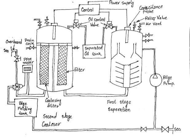
Oily Water Separator Working

How does an oily water separator work?

The complete unit is filled with clean water and after that the oil / water is pumped to the first stage of the coarse separating compartment. Here, oil with a lower density than water will rise to the surface with the aid of heating coils in this process. It’s known as a collection space.
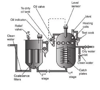
A sensor then senses the oil level and the oil is then dumped (according to ppm ) to the dirty oil tank via an oil valve.

The remaining oil – water mixture moves down to the fine separation compartment and moves slowly between the catch plates.

On the underside of these plates,more oil will separate and move outwards until it is free to rise up to the collection space.

And then ,Almost oil free water passes on to the second stage of the unit.

In the second stage, two coalesce filters are situated. The first filter removes any physical impurities present and promotes some filtration, the 2nd filter uses coalesce filter elements to achieve final filtration.

Clean water then leaves the 2nd stage on to a clean water holding tank or via a 15ppm monitor with audible and visual alarms overboard.

Coalescence :- Breakdown if surface tension between the oil droplets in an oil-water mixture which causes them to join and increase in size.

Suggested Read: filter

Working and Construction
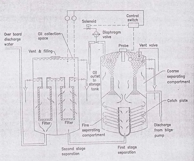
lt is the operation of an oily water separator with a fifteen ppm monitor. The separation of fine water in the separated fixed place in two stages, in the first stage of separation is by gravity whereas in the second stage the separation is by coalescing filter.

Oily water separator mainly consists of 3 units

  1. Separator unit
  2. Filter unit
  3. control unit (oil content monitoring)

A. Separator Unit

This unit consists of catch plates which are inside a coarse separating compartment and an oil collecting chamber.

The boost pump delivers clean sea water to the first stage of the separated through the inlet valve.

The vent is kept open till all the air is removed from the seperator;the oily water mixture is then pumped through the separator inlet pipe into course separating compartment .

Here, because of its lower density, some oil can separate and rise into the oil collection spaces.

The remaining oil-water mixture now flows down into the fine separating compartment and passes gradually between the catch plates.

More oil can separate on the underside of these plates and travel out until the oil-collecting space is free to rise.

Almost oil-free water passes through the central pipe and leaves the separator unit. The purity at this point will be hundred parts per million or less.

An automatically operated valve releases the oil into a storage tank.

(The oil drain valve from the top of the first stage separated is a diaphragm controlled piston valve control air and supplied to the diaphragm through for the solenoid operated pilot valve, the capacitance probe senses oil quantity in the collection space and energizes the form allied to the control switch, was a passive downwards from the first to the second phase coalesce the two central pipe)

Air is released from the Unit By A Vent valve .

Steam or electric heating coils are provided in the upper and sometimes the lower part of the separator, depending upon the type of oil to be separated. (heating reduces viscous drag of oil and thus makes separation of oil and water Easier)

where greater purity is required the almost oil free water passes to a filter unit,the water flow in turn through two filter stage and the oil removed passes to oil collecting spaces.

The first stage filter removes physical impurities present and promotes some points fine separation.

2.The Filter Unit

This is a separate unit whose input comes from the discharge of the first unit.
● The unit consists of three stages – the filter stage, the coalescer stage and the collection chamber.

● The impurities and the particles are separated by a filter and settled down to the bottom for removal.

The second stage filter uses coalescer inserts for final de-oiling.

Coalescence is the breakdown of surface tension between oil droplets in and oil water mixture which causes them to join and increase in size.

Coalscer filter

Oil content of the final discharge is the last thing ppm,in case the discharge of water after the second stage is more than fifteen ppm .

The monitor synthesis and gives an audible and visual alarm in the engine room,at the same time the monitor and the signal to a three way valve on the overboard discharge line which closes the overboard and opens to be those tanks.

The sensor reports the normal operation, once the oil content drops below fifteen between the test cocks can be used to ascertain the levels of oil and water manually.

The oil from the collecting spaces is drained manually, as is usually required, about once a week.

Filter inserts will require a change in the period of useful life, depending on the operating conditions.

3. Oil Content Monitoring Unit

Regulations on the discharge of oily water, set a concentration limit of ,up to 15 parts per million.

A monitor is required to measure these values and to provide both continuous recordings and alarms where the level allowed is exceeded.
The principle used is that of ultra-violet fluorescence.

This is the emission of light by a light-absorbing molecule.

Energy is lost during the short time between absorption and emission, and light of a longer wavelength is emitted. Oil fluoresces more readily than water, so this provides the means to detect it.
A sample is drawn off from the overboard discharge and passes through sample cell (Figure ).

The ultraviolet light is directed to the sample and the fluorescence is monitored by a photoelectric cell.

The measured value is compared to that of the maximum desired value in the controller / recorder.

When an excessive level of contamination is detected, the alarm is sounded and the diverting valve is operated.

The discharging liquid is then passed to a slop Vault.

Alarms and shutdown

If the 15 ppm oil content monitoring device detect discharge of oil content over 15 ppm,it shuts the unit down and activates the alarm. But in some cases only alarm is there.

Oily Water Separator Requirements

1.As per MEPC 107(49), a bilge alarm or an Oil Content Control unit, which provides for an internal recording of alarm conditions, must be certified by an approved organization.

2.The OCM equipped with the oily water separator must be tamper-proof.

3. When freshwater is used for cleaning or zeroing purposes, the OCM must trigger and sound an alarm.

4.Separator capable of achieving 15 ppm on type C emulsion

Reason for improper functioning of and Oily Water Separator

1. The principle of separation of Oily water separator on which the separator function is the gravity differential between oil and water.

The force acting on oil Globule to move in the water is proportional to the difference in weight between the oil particle and a particle of water of equal volume.

The resistance to the movement of globule depends on its size and viscosity of the fluids.

Thus in general, a High rate of separation is favoured by

  • large size of globule.
  • elevated temperature of the system *which affects both of specific gravity differential of the oil and water and the viscosity of the water) And the use of seawater

2. Pumping Consideration

Since the rate of separation depends on the oil Globule size it will be appreciated that any disintegration of oil globules in the oily feed to the separator should be avoided and this factor can be seriously affected by the type and rating of the pump used.

A large number of bilge pumps are centrifugal and often they are used as a supply pump for the separator.

Thus, Charan the supply and produce small oil droplets which dispersed throughout the water, which in turn ma y seriously affect the separation effectively

A positive displacement pump for example slow running double vane, screw, reciprocating or gear pump enables a much better performance to be achieved from the separator as they do not produce large quantity of a small droplets. using pump after the separator may give a discharge having less than 15 PPM concentration without using 2nd Stage filters.

From above two points it is evident that even if the separator is well maintained and correctly operated following factors can cause improper functioning of the separator.

  1. Throughput of the separator is excessive
  2. excessive rolling and pitching of the ship causing disintegration of wall globules.
  3. pump type or and rating is not matching causing too much of turbulence.
  4. Turbulence caused due to pumping rate.

Further Read:

In this Article, I have written answers to all Questions arises on the Topic Oily Water Separator which I have learned from my faculty or from books.

Anything I missed ? Please write it down in the comment section and don’t forget to share it, because sharing is caring.

FAQ ( Frequently Asked Questions )

What is the purpose of an oily water separator?

It’s Purpose is used to separate Oil from mixture of oil and water. It is used on ship to prevent from making impure sea water. Directly discharge of oily water in sea cause pollution and damage to life of birds and sea animals.

What are the types of oily water separator?

1. Coalescing plate oil water separators treat water to ~10 ppm oil content.
2. Hydrocyclone oil water separators treat water to ~5 ppm oil content.
3. Vertical gravity oil water separators water to ~50 ppm oil content.

What are the three segments of oily water separator?

1. Separator Unit
2. Filter Unit
3. Oil Monitoring Control Unit

Check Out Other Important Topics

IC EngineImportant PDFsBoilersSynergy Maritime ExamNaval ArchMEO Class 4
Interview QuestionsDifference BetweenTypes of PumpsAuxiliary MachinesTypes of ValvesHome

Wikipedia

Lubrication in 4 four stroke engine with diagram

How lubrication in 4 stroke engine Takes place ? It is done either by splash lubrication or Pressure lubrication system. In this article, I will describe step by step so that you can understand Lubrication in 4 four stroke engine ( auxiliary engine ) with diagram engine easily.

Try to understand the layout Lubricating system of 4 stroke or Auxiliary engine.It help you in visualising all the parts and how oil moves from sump to all parts and come back to sump of the engine.

Suggested Read : Types of Lubrication

Layout of Lubricating system of 4 stroke or Auxiliary engine

Here is description of the lubrication system for a four-stroke engine highlights the key processes involved in ensuring the efficient functioning of engine components. Here’s a more structured breakdown of the layout and operation of the four-stroke engine’s lubricating system:

Lubricating System Overview:

The lubricating system of a four-stroke engine typically uses a wet sump lubrication system, where oil is stored in a sump located at the bottom of the engine. A lube oil pump, powered by the engine itself, circulates the lubricating oil through the engine’s various components in a closed loop.

lubrication in 4 four stroke engine

Key Components and Process Flow:

1.Lube Oil Sump: The oil is stored in the sump located at the bottom of the engine. The sump holds the oil and acts as the source from which the lubricating oil pump draws oil.

2.Lube Oil Pump: The lube oil pump is driven by the engine and is responsible for circulating oil throughout the system. It pumps oil from the sump and directs it through the rest of the system.

3. Primary Filter: After being drawn from the sump, the oil first passes through a primary filter, which removes larger particles and impurities from the oil, ensuring cleaner oil flows through the system.

4. Oil Cooler: After filtration, the oil passes through an oil cooler, which reduces the temperature of the oil, ensuring that it can efficiently lubricate engine components while preventing overheating.

5. Main Filter: The oil then passes through the main filter for final filtration, removing any remaining impurities.

6. Oil Distribution: After passing through the cooler and main filter, the oil splits into two separate lines:

  1. Lubricating Main Bearings and Crankshaft:
    • One line directs oil to the main bearings. From there, oil passes through holes in the crankshaft, reaching the crankpin for lubrication.
    • The oil continues inside the crankshaft, moving toward the piston pin (gudgeon pin) for lubrication. The lubricated piston pin ensures the smooth movement of the piston inside the cylinder.
  2. Lubricating Cylinder Liners:
    • Through the end of the gudgeon pin, oil also lubricates the cylinder liners, ensuring minimal friction between the piston and the cylinder walls.
    • Scraper rings on the piston remove excess oil from the cylinder liner, directing it back to the sump.

7. Lubricating Gear System: The second line from the main filter goes to lubricate the engine’s gear system, which includes various pumps and components attached to the crankshaft.

  • Components like the lube oil pump, jacket water pump, governor, rocker arm pump, and fuel oil pump are all lubricated from this line to ensure smooth operation.

Key Lubricated Components:

  • Main Bearings: Support the crankshaft, allowing it to rotate smoothly.
  • Crankshaft and Crankpin: Transmit the engine’s power; lubrication is critical to reduce wear due to friction.
  • Piston Pin (Gudgeon Pin): Connects the piston to the connecting rod, needing lubrication for smooth piston movement.
  • Cylinder Liners: The inner walls of the cylinder where the piston moves up and down; lubricated to reduce friction and wear.

Piston Cooling (To be Discussed Later):

  • In addition to lubricating the engine components, the lube oil system also plays a role in piston cooling, where oil circulates through or around the piston to regulate its temperature. You plan to explain this further in a future section.

Line Diagram of 4-stroke engine lubricating system

Lubricating oil from the oil sump tank >>> Primer filter >>> The lubricating oil pump >>> lubricating oil cooler >>> lubricating oil pressure relief valve >>> lubricating oil filter >>> lubricating oil main pipe.

Now lubricating oil main pipe branched into two lines :-

1. The one line lubricates the main bearing shell, crank pin bearing shell and piston pin bush.

2. While the other line lubricates the cam shaft bearing shell, tappet surroundings, governor and idle gear bush.

Then they will come together to drop into the sole plate. In some modes of engines, the valve rocker arm is lubricated in this circulation.

Pressure Type Lubrication System

This system ensures that all critical engine parts receive continuous lubrication, minimising wear and tear, reducing friction, and preventing overheating of components.

Here, a provided an in-depth explanation of the pressure-type lubrication system in a four-stroke engine, focusing on the key parts that require lubrication to ensure smooth engine operation. Here’s a clearer breakdown of the components and their lubrication process: …

The above see that lubrication system is pressure type lubrication system. Now we see all the parts which is used for lubrication. The main parts which is lubricated are :-

  • Main Bearings
  • Crank Pin or Bottom end bearings
  • Top end bearings or Gudgeon pin Or piston pin
  • Cylinder liner lubrication
  • Camshaft
  • Crankshaft drive
  • Governor drive
  • Turbocharger
  • Rocker arm system

Components and Lubrication Details:

  1. Main Bearings:
    • The main bearings support the crankshaft and are connected to the connecting rod. Due to the heavy loads they bear, proper lubrication is critical to reduce wear and ensure smooth motion.
    • Lubrication Process: Lube oil, under pressure from the lube oil pump, passes through holes in the bearings to provide continuous lubrication.
  2. Crank Pin Bearings (Bottom End Bearings):
    • These bearings connect the crankshaft to the crank pin, allowing the conversion of reciprocating motion (up and down movement of the piston) into rotary motion.
    • Lubrication Process: The oil is transferred from the main bearing through an internal passage in the crankshaft, which delivers the oil to the crank pin bearings.
  3. Gudgeon Pin (Piston Pin) or Top End Bearings:
    • The gudgeon pin connects the piston to the connecting rod, experiencing reciprocating motion. Proper lubrication is critical to prevent friction between the piston and the connecting rod.
    • Lubrication Process: Oil is delivered to the gudgeon pin through passages inside the crankshaft, continuing the flow from the crank pin.
  4. Cylinder Liner Lubrication:
    • The cylinder liner forms the sliding surface for the piston. Lubrication here is necessary to reduce friction between the piston and the liner.
    • Lubrication Process: Oil from the gudgeon pin passes through the end of the piston pin and reaches the cylinder walls. Scraper rings on the piston distribute the oil over the liner, while excess oil is scraped back into the sump.
  5. Camshaft:
    • The camshaft drives the operation of various pumps and other engine components by controlling the timing of the valve operation (inlet and exhaust valves).
    • Lubrication Process: A nozzle is provided on top of the camshaft, where oil is sprayed to lubricate the gears involved in the camshaft’s operation.
  6. Crankshaft Drive:
    • The crankshaft drive also requires lubrication, particularly in the areas where gears are involved in transmitting power to other components.
    • Lubrication Process: A nozzle sprays oil onto the gear meshes to ensure proper lubrication and reduce friction.
  7. Governor Drive:
    • The governor controls the engine’s speed by regulating fuel delivery based on load conditions.
    • Lubrication Process: The governor mechanism is lubricated via oil delivered through a dedicated piping system to the gear mesh, ensuring smooth operation.
  8. Turbocharger:
    • Some engines use the same lube oil system to lubricate the bearings of the turbocharger. The turbocharger has two main bearings: the turbine-side bearing and the blower-side bearing.
    • Lubrication Process: A branch of the lube oil system is used to deliver oil to both bearings, ensuring proper lubrication for the high-speed rotating shaft of the turbocharger.
    • Alternative Lubrication: In some engines, splash lubrication is used for the turbocharger bearings. The bearings dip into the oil in the sump, allowing them to be lubricated as they rotate.
  9. Rocker Arm System:
    • The rocker arm controls the opening and closing of the inlet and outlet valves, and its lubrication is essential for smooth valve operation.
    • Lubrication Process: In some engines, the rocker arm system is lubricated by the same lube oil pump. After passing through the filters, one oil line branches off to lubricate the rocker arm.

Special Pump: In Daihatsu diesel engines, a special rocker arm pump (internal gear pump) is provided exclusively for lubricating the rocker arm system, offering precise control of lubrication in this area.

Line diagram of rocker arm system

Lubrication of rocker arm system are explained below :-

The Rocker arm lube oil tank >>> torchoid pump ( with safety valve ) >>> lube oil filter >>> Supply oil main pipe >>> rocker arm shaft bush >>> rocker arm end >>> returning main pipe >>> rocker arm lube oil tank

Rocker Arm Lube Oil Tank:

This tank stores the lubricating oil specifically for the rocker arm system. It is separate from the engine’s main lubrication system to ensure that the oil remains clean and free from contamination.

Torchoid Pump (with Safety Valve):

The torchoid pump is responsible for pressurizing and pumping the lubricating oil from the tank. The safety valve ensures that oil does not exceed safe pressure levels, protecting the system from damage.

Lube Oil Filter:

After the oil is pumped, it passes through a lube oil filter, which removes contaminants and impurities. This step is crucial for maintaining the quality of the oil used for lubrication.

Supply Oil Main Pipe:

The filtered oil travels through the supply oil main pipe to reach various lubrication points in the rocker arm system.

Rocker Arm Shaft Bush:

The oil first reaches the rocker arm shaft bush, providing lubrication to the bushings that support the rocker arm’s pivot point.

Rocker Arm End:

The oil then flows to the rocker arm end, where it lubricates the contact points responsible for actuating the engine’s valves.

Returning Main Pipe:

After lubricating the rocker arm, the oil returns through the returning main pipe to be recirculated back into the rocker arm lube oil tank.

Rocker Arm Lube Oil Tank (Return):

Some oil returns directly to the rocker arm lube oil tank from the oil pressure relief valve located at the end of the supply oil main pipe. This valve allows excess oil to be returned to the tank, preventing overpressure in the system.

Line Diagram of 2-stroke engine lubricating system

Lubricating oil from the oil sump tank >>> Primer filter >>> The lubricating oil pump >>> lubricating oil cooler >>> lubricating oil pressure relief valve >>> lubricating oil filter >>> lubricating oil main pipe.

Now lubricating oil main pipe branched into two lines :-

1. The one line lubricates the main bearing shell, crank pin bearing shell and piston pin bush.

2. While the other line lubricates the cam shaft bearing shell, tappet surroundings, governor and idle gear bush.

Then they will come together to drop into the sole plate. In some modes of engines, the valve rocker arm is lubricated in this circulation.

Lubricating Oil pump :- lubricating oil pump used here is external gear pump. It is located at the front of the engine and is powered by the crankshaft via a coupling or a gear wheel.

Note :- In some engine splash lubrication system is used. In this lubrication system, lube oil is submerged partially. when crankshaft rotates, it splash the lube oil on surfaces.

How piston cooling is done in 4 stroke engine ?

As piston get hot too much because it is directly in contact with combustion. So, we need to to cool it working properly. Otherwise failure of Piston. Piston cooling is done by the Nozzle provided near the under space of piston.

This is all about lubrication of 4 stroke engine or auxiliary engine.

FAQ ( Frequently Asked Questions )

Which type of lubrication system is used in stroke engine?

 type of lubrication system used as a dry-sump type, wet-sump type, force-feed type, or splash type.

Check Out Other Important Topics

IC EngineImportant PDFsBoilersSynergy Maritime ExamNaval ArchMEO Class 4
Interview QuestionsDifference BetweenTypes of PumpsAuxiliary MachinesTypes of ValvesHome

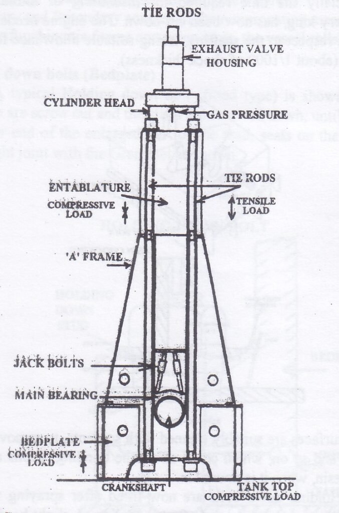
A-frame of IC Engine

An A-frame in the context of an internal combustion (IC) engine typically refers to a structural component used in the engine’s assembly or installation, often related to mounting or support systems.

A frame in IC Engine

Key Features of A-Frames in Large Crosshead Engines:

  1. Support for Cylinder Block: A-frames are essential for stabilizing the cylinder block, being fitted to transverse girders and ensuring the block remains firmly secured during operation.
  2. Assembly Design:
    • Tie-bolts pass through these A-frames, enhancing strength and resilience.
    • In some designs, multiple A-frames are combined with the crankcase casing to form a rigid box structure, which is attached to the engine.
  3. Construction:
    • A-frames are fabricated from flat steel plates that are welded together, creating a robust component that provides necessary support.
    • These frames serve as mounting points for several key engine components, including:
      • Crosshead guides
      • Main crankcase covers
      • Piston cooling supply pumps and return drains
  4. Alignment and Rigidity:
  • A-frames are precisely aligned on the bed plate to ensure the correct positioning of all mounted components, forming a rigid structure that maintains alignment.
  • This assembly helps accommodate the higher lateral forces introduced by long and super long stroke engines, which use relatively short connecting rods. These rods, despite lowering the engine’s overall height, increase the angle and consequently, the lateral force component.

Construction:

  • Materials: Commonly made from steel or aluminum to ensure strength while keeping weight manageable.
  • Design: The triangular shape of the A-frame (like a capital A) provides excellent load-bearing capabilities.

Advantages of A-Frame

  • Greater Structural Rigidity: Provides enhanced strength and stability to withstand operational stresses.
  • More Accurate Alignment: Ensures precise alignment of the crosshead, which is crucial for engine efficiency and longevity.
  • Uniform Force Distribution: The design allows for a more uniform distribution of forces, leading to a lighter structure without compromising strength.
  • Improved Oil Tightness: The robust construction helps maintain seals and improve oil retention, enhancing engine performance and reducing leaks.

UMS REQUIREMENTS

What are UMS Requirement ?

The UMS (Unmanned Machinery Space) requirements, as outlined in the SOLAS (Safety of Life at Sea) regulations from 1977, are essential for ensuring the safety and functionality of vessel machinery while minimizing the need for crew presence in machinery spaces.

Here’s a concise summary of the UMS requirements you mentioned:

UMS Requirements

1.Bridge Control of Propulsion Machinery:

  • The watchkeeping officer must have the ability to take emergency control actions.
  • Control systems should be simple and user-friendly.

2.Centralized Control and Instrumentation:

  • Centralized controls in the machinery space must allow for quick access in emergencies.
  • Controls must be comprehensive and easily reachable.

3.Automatic Fire Detection System:

  • Alarms and detection devices should operate rapidly.
  • Multiple well-partitioned detectors must be installed for quick response.

4.Fire Extinguishing System:

  • In addition to hand-held extinguishers, a remote control fire station is essential.
  • The station should provide control over pumps, generators, quick-closing valves, ventilation, and extinguishing media.

5.Alarm System:

  • A comprehensive alarm system must be established for the control of the accommodation area.

6.Automatic Bilge High-Level Fluid Alarm and Pumping Units:

  • Bilge sensing devices must have alarms and automatic pump activation/deactivation.

7.Automatic Start of Emergency Generator:

  • Emergency generators should be connected to a separate busbar and primarily serve to prevent blackouts.

8.Local Planned Control of Essential Machinery:

  • Controls should be significantly localized for immediate access and management.

9.Adequate Settling Tank Storage Capacity:

  • Properly designed storage systems must be in place for pollutant management and system efficiency.

10.Designed Safety Systems:

  • Systems should automatically isolate malfunctioning segments and restore control.

11.Steering Gear Operations:

  • Features should allow for shutdown in case of serious malfunctions.
  • Stand-off options and load-sharing mechanisms should be implemented for auxiliary engines.

12.Deadman Alarm:

  • An alarm system to ensure that vessels can detect operator incapacitation or emergencies.

These requirements help ensure that the vessel can operate safely and efficiently without the constant presence of crew members in the machinery space, while also preparing for emergencies where human intervention is necessary. If you have further specific queries regarding these requirements, feel free to ask!

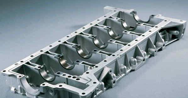
Bed Plate – Functions And Structure of IC engine

What is a Bedplate of Diesel Engine ?

The bed plate forms the foundation of the engine (or constructions )on which the other structural component such as A-frame, all column, and Guides are mounted and it can withstand heavy fluctuating stresses from working parts.

Bedplate supports the Load of the Engine and it’s other Constructional parts and provide a base for the large mass.

Bed Plate

What are the Functions of a Bed Plate ?

The functions of a bed plate, particularly in the context of marine or industrial engines, are critical for ensuring proper operation, stability, and efficiency. Here’s a consolidated overview based on your points:

  1. Load Transmission: The bed plate transmits the engine’s load, including the propeller thrust, to the ship’s structure. It distributes this load over an adequate area, ensuring that the crankshaft remains aligned for optimal performance.
  2. Oil Management: It collects crankcase lubrication oil and facilitates its return to the drain tank for recirculation, maintaining proper lubrication and cooling of engine components.
  3. Structural Integrity: The bed plate is bolted to the tank top, which is reinforced with thicker plates and girders to provide additional strength and stability, ensuring it can support significant forces during engine operation.
  4. Support Base: Acting as a foundational element, the bed plate provides essential support to the entire engine structure, contributing to the overall stability of the system.
  5. Static Weight Support: It bears the static weight of the entire engine and its components, ensuring that forces are effectively transferred to the ship or structure.
  6. Dynamic Load Support: The bed plate also supports the dynamic loads generated by the engine’s running gear, absorbing vibrations and shocks that occur during operation.
  7. Crankshaft Alignment: The crankshaft fits into the bed plate via main journal bearings, ensuring the crankshaft is held in perfect alignment for efficient functioning and reduced wear.

These functions collectively ensure that the engine operates smoothly, safely, and efficiently, which is crucial for the overall performance of marine vessels or industrial machinery.

What are the fundamental requirements of Bed plate ?

The fundamental requirements of a bed plate in an engine are essential to ensure its structural integrity, functionality, and efficiency. Here’s a breakdown of each requirement:

  1. Strength
    The bed plate must have sufficient strength to bear the static and dynamic loads of the engine, including the weight of the engine components and the forces generated during operation.
  2. Lightness
    While maintaining strength, the bed plate should be designed to be as light as possible to avoid adding unnecessary weight to the overall engine structure, especially in marine and automotive applications where weight efficiency is crucial.
  3. Toughness
    Toughness is necessary to withstand impact and fatigue stresses. The bed plate must endure repeated cycles of mechanical loads without cracking or deforming, ensuring long-term durability.
  4. Simple Design
    A simple design facilitates ease of manufacturing, assembly, and maintenance. Simplicity also ensures that the bed plate remains reliable while minimizing potential points of failure.
  5. Seal
    The bed plate must be able to seal off the crankcase to prevent oil leaks and ensure that the lubrication system operates effectively, keeping contaminants out of the engine.
  6. Access
    Access points should be provided in the bed plate for inspection, maintenance, and repairs of internal components like the crankshaft and bearings, ensuring efficient engine servicing.
  7. Dimensions
    The dimensions of the bed plate must be precise, fitting the engine structure perfectly to ensure proper alignment of components like the crankshaft, and ensuring compatibility with the overall design of the engine and surrounding structure.
  8. Rigidity
    The bed plate must maintain rigidity to prevent deformation under load, ensuring that the engine structure remains aligned and that mechanical stresses are distributed evenly.

These requirements ensure that the bed plate can provide the necessary support, alignment, and durability for efficient engine operation.

Read About : Difference between two Cross head and Trunk type piston engine

Construction

Sure! Here’s a simpler breakdown of the construction of bed plates:

1. Small Engine Bed Plates

  • Material: Small engines generally have bed plates made from one solid piece of cast iron.
  • Design: This design is a single casting, meaning it’s all one part, making it strong and stable.
  • Vibration Dampening: Cast iron helps absorb vibrations, making the engine run more smoothly.

2. Large Engine Bed Plates

  • Material and Structure: Large engines use fabricated mild steel for their bed plates.
  • Configuration: These have:
  • Longitudinal girders: These are long beams that run the length of the bed plate.
  • Cast steel transverse girders: These are shorter beams that support the crankshaft bearings, helping share the load evenly.

3. Material Requirements

  • Carbon Content: For large marine diesel engines, the materials used should have low carbon content (up to 0.23%). This helps the metal stay strong and easy to work with during construction.

4. Key Points in Bed Plate Construction

  • Strength and Rigidity: Bed plates must be strong enough to hold the engine without bending or breaking.
  • Vibration Control: Small bed plates use cast iron to help manage vibrations; larger bed plates may need special designs to do this.
  • Easy Maintenance: The bed plate should be designed so that engine parts can be easily reached for checking and repairs.

In short, the construction of bed plates is important for keeping engines stable and running smoothly, with different designs for small and large engines.

What are the forces act on bed plate

The forces are :-

  • Firing pressure (Cylinder gas pressure )
  • Forces of inertia of moving masses
  • Side thrust due to movement of connecting rod.
  • Whole weight of engine act on the bed plate.
  • Torque due to rotation of propeller.
  • Hull deflection.
  • Vibrations forces (It is generated due to fluctuations in torque,shock loading and thermal stress )
  • Rough weather (Forces due to ship’s movement in heavy seas).

Materials use

◆ Cast iron

Hybrid: fabricated mild steel for longitudinal Cast steel for transverse.

Maintenance / What are the checks to be carried on the bed plate during inspections

Since Bedplate is the base of the Engine it should be in proper order for the proper functioning of the Engine. And for that it should be regularly checked and maintenance should be carried out.

Maintaining the bed plate is crucial for the proper functioning of the engine. Regular inspections are essential to ensure its integrity and performance. Below are key checks to perform during inspections:

1. Cracks

  • Common Issue: Cracks often develop over time due to prolonged use and heavy loading.
  • Areas to Inspect:
  • Welded Joints: Examine the areas where transverse girders connect to longitudinal girders.
  • Bearing Pockets: Check under the bearing pockets for radial cracks or cracks along the pocket line.
  • Tie Bolt and Bolt Holes: Look for radial cracks at tie bolts and around the holes for frame bolts.
  • Lightening Holes: Inspect around the lightening holes in the bed plates and girders.
  • Main Bearing Keeps: Inspect the base of the main bearing keeps for any signs of cracking.

2. Welding

  • Inspection: Check the condition of welding joints, especially if recent welding has been done, ensuring there are no defects.

3. Faulty Casting

  • New Deliveries: Newly delivered engines with cast components should be tested for defects in casting.

4. Corrosion

  • Vulnerability: Since the bed plate is located at the lowest part of the engine, it is prone to corrosion. Inspect it for any signs of rust or degradation.

5. Loose Frame

  • Impact of Loading: Loose frames can occur due to excessive loading or issues with tie rods.
  • Check Tie Rods: Ensure that tie rods connecting the bed plate to the A-frame and engine entablature are tight and that no part of the bed plate is loose.

6. Faulty Holding Down Bolts

  • Inspection for Tightness: The holding down bolts secure the bed plate to the ship’s bottom structure. Regularly check these bolts to ensure they are secure.

7. Oil Leaks

  • Lubrication System: The bed plate is involved in storing and transferring lube oil. Inspect the bed plate and joints for any oil leaks, which can indicate issues with seals or connections.

Regular checks on cracks, welding, casting quality, corrosion, frame integrity, bolt tightness, and oil leaks are critical for maintaining the bed plate’s health and ensuring optimal engine performance.

What are the cause of breaking of bed plate ?

The breaking of a bed plate can occur due to several factors, including:

  1. Overloading: Excessive weight or force beyond the bed plate’s designed capacity can lead to fractures or failures.
  2. Uneven Loading: If engine loads are not evenly distributed, it can create stress concentrations that weaken the bed plate and cause breaking.
  3. Faulty Maneuvering Techniques: Incorrect handling or operation of the engine, such as abrupt changes in speed or direction, can apply undue stress on the bed plate.
  4. Loosened Tie Bolts: If the bolts securing the bed plate become loose, it can lead to misalignment and increased stress in certain areas, making the bed plate susceptible to breaking.

Addressing these issues through proper design, maintenance, and operation can help prevent bed plate failures.

Faults in Bedplate

Faults in a bed plate can lead to operational issues and may affect the performance of the engine. Here are some common faults:

1.Cracks: Cracks can develop due to overloading, fatigue, or manufacturing defects, compromising the structural integrity of the bed plate.

2.Oil Leaks: Oil leaks can occur from damaged seals or joints, leading to lubrication issues and potential engine damage. This can often be caused by wear or improper installation.

3.Loose Chocks: Chocks are used to secure the bed plate in position. If they become loose, they can lead to misalignment of the engine components, causing vibrations and further mechanical issues.

    Regular inspections and maintenance can help identify and address these faults before they lead to serious problems.

    Source : https://www.wartsila.com/encyclopedia/term/bedplate

    Also Read : Fresh Water Generator On ships

    Read more : Boiler Mountings

    Check Out Other Important Topics

    IC EngineImportant PDFsBoilersSynergy Maritime ExamNaval ArchMEO Class 4
    Interview QuestionsDifference BetweenTypes of PumpsAuxiliary MachinesTypes of ValvesHome

    Difference Between Crosshead And Trunk Type Piston engine

    Difference between Crosshead and Trunk type Piston engine

    Difference between crosshead and trunk type Piston engine are as follows :-

    Difference between Crosshead and Trunk type Piston engine

    Crosshead Type Engine

    It looks like you’d like the crosshead type engine section expanded with the details you provided. Here’s a refined version in a formal tone that aligns with the earlier structure of the blog post:


    Crosshead Type Engine: Design and Features

    1. Connecting Rod and Piston Rod
      A defining feature of the crosshead type engine is the presence of both a connecting rod and a piston rod. The piston rod connects the piston to the crosshead assembly, which in turn is connected to the connecting rod. This distinction separates crosshead engines from trunk type engines, which lack a piston rod.
    2. Diaphragm Separation
      Crosshead engines are equipped with a diaphragm that separates the cylinder space from the crankcase. This feature prevents the mixing of lubricants, allowing for different lubrication systems to be used in the cylinder and the crankcase, thus enhancing overall engine performance and longevity.
    3. Bearing Assembly at the Upper Part
      In the upper part of the crosshead engine, the connecting rod is linked to the crosshead assembly. This assembly, which consists of a crosshead block, pins, and slippers, plays a critical role in ensuring smooth movement and transferring forces efficiently. The crosshead assembly connects to the lower part of the piston rod, which is rigidly fixed to the piston, creating a solid structure that minimizes stress and wear.
    4. Separate Cylinder Lubrication
      One of the key features of the crosshead engine is its separate lubrication system for the cylinder and the crankcase. The cylinder uses a distinct oil from the crankcase, tailored specifically for the high-temperature environment of the cylinder. This system enhances the engine’s efficiency and prolongs its lifespan.
    5. Transverse Force Management
      The transverse forces generated by the oscillation of the connecting rod are managed by the crosshead and its guides. These forces are transmitted through the crosshead guides to the engine structure, reducing wear on the piston and piston rod assembly.
    6. Crosshead Assembly as a Connecting Mechanism
      The crosshead assembly is a critical connecting mechanism between the piston rod and the connecting rod. The piston is rigidly fixed to the piston rod, and this rigid connection ensures that forces are efficiently transmitted from the piston to the connecting rod via the crosshead assembly.
    7. Higher Torque at Low Speeds
      Crosshead engines are capable of generating higher torque at lower speeds, making them ideal for applications requiring heavy-duty, low-speed performance. This is a key advantage in marine propulsion systems and other industrial applications where low-speed operation is crucial.
    8. Increased Height Requirements
      Due to the complexity of the crosshead assembly and the inclusion of both a piston rod and a connecting rod, crosshead engines require more vertical space. For the same power and speed, a crosshead engine will have a taller profile than a trunk type engine.
    9. Transverse Thrust Transmission
      The transverse thrust generated within the engine is effectively transmitted to the engine structure through the crosshead guides, which absorb and manage these forces. This ensures that the engine operates smoothly without excessive stress on the moving parts.
    10. Higher Manufacturing Costs
      The complexity of the crosshead assembly and the need for separate lubrication systems contribute to higher manufacturing costs. The additional components and engineering precision required make these engines more expensive to produce, though they offer superior durability and performance under demanding conditions.
    11. More Height for Same Power and Speed
      As mentioned earlier, due to their complex structure, crosshead engines require greater height for the same power and speed when compared to trunk type engines. This can be a limitation in applications where space is a critical factor.
    12. Efficient Use of Low-Grade Fuel
      Crosshead engines are designed to handle low-grade fuels efficiently, as their operation at lower speeds allows more time for complete combustion. This ability makes them ideal for applications where fuel cost savings are a priority.

    Trunk type engine

    It looks like you’re reiterating the details of the trunk type engine. Here’s a refined version in formal tone that incorporates your points:


    Trunk Type Engine: Design and Features

    1. Absence of a Piston Rod
      In a trunk type engine, only the connecting rod is present, directly connecting the piston to the crankshaft. There is no piston rod, which simplifies the engine design. This contrasts with crosshead engines, which have both a connecting rod and a piston rod.
    2. No Diaphragm
      Unlike crosshead engines, the trunk type engine has no diaphragm separating the cylinder from the crankcase. As a result, there is no physical barrier between the two, which allows for a unified lubrication system.
    3. Direct Connection to Piston via Gudgeon Bearing Assembly
      The upper part of the connecting rod in a trunk type engine is connected directly to the piston through a gudgeon bearing assembly. This eliminates the need for additional components like a crosshead, simplifying the engine structure.
    4. Unified Lubrication System
      In trunk type engines, the same lubrication oil is used for both the cylinder and the crankcase. While this simplifies maintenance, it can potentially result in increased wear due to the mixed operating conditions.
    5. Piston Skirt Absorbs Transverse Thrust
      The piston skirt in trunk type engines absorbs the transverse thrust caused by the oscillation of the connecting rod. This function, performed by the crosshead assembly in crosshead engines, is managed by the piston skirt in trunk engines.
    6. No Crosshead Assembly
      In trunk type engines, the connecting rod is attached to the piston via a gudgeon pin, and there is no crosshead assembly. This significantly reduces the complexity of the engine compared to the crosshead type.
    7. High Power at Medium or High Speeds
      Trunk type engines are designed to operate efficiently at medium to high speeds, where they produce high power output. This makes them suitable for applications where speed is a critical factor.
    8. Compact Design and Reduced Headroom
      One of the advantages of trunk type engines is their compact design. They require less headroom compared to crosshead engines because there is no piston rod or crosshead assembly. This makes them ideal for installations where space is limited.
    9. Piston Skirt Handles Side Thrust
      The side thrust created by the movement of the crankshaft and connecting rod is absorbed by the piston skirt in trunk type engines. This design concentrates the mechanical stress on the piston, requiring the skirt to be strong enough to withstand these forces.
    10. Lower Manufacturing Costs
      Trunk type engines have lower manufacturing costs due to their simpler design and fewer components. The absence of a crosshead assembly and diaphragm reduces the complexity of the engine, making it more cost-effective to produce.
    11. Less Height for Same Power and Speed
      Due to the simplified design, trunk type engines require less vertical space for the same power output and speed compared to crosshead engines. This reduction in height is a significant advantage in applications where space constraints are a factor.
    12. Efficient Use of Low-Grade Fuel
      Trunk type engines can efficiently use low-grade fuels, making them cost-effective in operations where fuel quality is variable. The engine’s ability to run efficiently on such fuels provides flexibility in fuel choices depending on operational requirements.

    Here a Very Easy table comparing crosshead type engines and trunk type engines based on the information you’ve provided:

    FeatureCrosshead Type EngineTrunk Type Engine
    Piston RodHas both a connecting rod and a piston rod.Only the connecting rod; no piston rod.
    DiaphragmHas a diaphragm separating the cylinder from the crankcase.No diaphragm.
    Upper Part ConnectionConnecting rod is connected to the piston rod via a crosshead assembly.Connecting rod is directly connected to the piston via a gudgeon bearing assembly.
    Lubrication SystemSeparate oils for cylinder and crankcase.Same lube oil used for both the cylinder and crankcase.
    Transverse Thrust AbsorptionTransverse thrust is absorbed by the crosshead and its guide.Transverse thrust is absorbed by the piston skirt.
    Crosshead AssemblyHas a crosshead assembly connecting the piston rod to the connecting rod.No crosshead assembly; uses a gudgeon pin to connect the connecting rod to piston.
    PerformanceDevelops high torque at low speeds.Produces high power at medium or higher speeds.
    Space RequirementsRequires more height due to complex structure.Requires less headroom; more compact design.
    Transverse Thrust HandlingThrust is transmitted to engine structure through crosshead guides.The piston skirt handles the side thrust.
    Manufacturing CostsHigher due to complexity and additional components.Lower due to simpler construction.
    Height for Same Power and SpeedMore height needed for the same power and speed.Requires less height for the same power and speed.
    Fuel EfficiencyCan efficiently use low-grade fuel over time due to longer combustion.Can also use low-grade fuel efficiently, suitable for various applications.

    This table provides a clear and easy comparison between the two engine types. Let me know if you’d like to adjust or add more details!

    Follow us on Twitter

    People also ask

    What is trunk type engine ?

    A type of an internal combustion engine in which the connecting rod is directly connected to the piston by Gudgeon pin (also called piston pin ).

    Advantage of crosshead type engine ?

    Advantage are :-

    1. The Cross head type engine are able to devlop higher power at lower rotational speed of the engine than trunk type engines.It is because the space available for the crosshead bearing is greater than the space within the piston for gudgeon bearing assembly.
    2. The combustion product contamination of crankcase lube oil is less than the trunk type engine.
    3. Total costs of lubricants of crosshead engine is less than the trunk type engine having same power.

    What is a cross head engine ?

    Why do pistons have skirt ?

    Skrt do two functions

    1.The piston skirt consists of spaces for gudgeon pin which transmits power to the con. rod

    2.The skirt also help in transmitting the side thrust produced by the connecting rod.

    What is the name the portion below the piston boss?

    Ans :- Skirt
    ring belt: is the upper-middle part of the piston when the piston rings are located.

    pin

    boss: is the lower-middle part of the piston which contains the piston pin.


    What are the 3 types of piston rings?


    Why crosshead lubrication is difficult?


    What is the largest diesel engine in the world?


    What is a cross head type diesel engine?


    What is a crosshead bearing?
    a sliding member of a reciprocating engine for keeping the motion of the joint between a piston rod and a connecting rod in a straight line.

    Can you use a piston with a broken skirt?


    Nope, no good, never, shouldn’t even think about it, NOT IN ANY ENGINE. That’s just asking for more damage or destruction.

    Can you reuse old Pistons?


    TOP 50+ Frequently Asked IC Engine Interview Questions

    IC Engine Interview Questions are one of the most asked questions while facing an interview.

    If you have done Mechanical Engineering or Equivalent ( Marine Engineering ) and on the basis of that you are applying for any job, then definitely you will be asked questions related to your Degree.

     IC Engine Interview Questions

    In such case if you are trying to find out what are the possible questions that can be asked in an interview. So here are the list of Interview Questions mostly asked in interviews related to IC Engine.

    Frequently Asked IC Engine Interview Questions

    1. What do you mean by IC Engine and how it operates ?

    2. Why it is called IC Engine?

    3. What are the types of IC Engine? Click To Read Answer

    # Discuss Spark Ignition (SI) and Compression Ignition (CI) engines.

    4. What is a 2 Stroke Engine?

    5. What is a 4 Stroke Engine?

    6. What do you mean by Stroke of an Engine?

    7. What is difference between 2 Stroke Engine and 4 Stroke Engine? Click To Read Answer

    8. What is Clearance Volume?

    9. What are the four processes of Combustion in an Engine?

    10. What is an Idle stroke?

    11. What is Bumping Clearance?

    12. How do you Calculate Mechanical efficiency of an IC Engine?

    14. What is Scavenging?

    15. Why Scavenging is required?

    17. What are the types of Scavenging?

    18. What is Super charging?

    19. What is Bed Plate? Click To Read Answer

    20. What is A-Frame?

    21. What is Crankshaft?

    22. How crankshaft are constructed?

    23. How crankshafts are Lubricated ?

    22. How Cylinder Lubrication is done in 2 Stroke Engine?

    23. How Cylinder Lubrication is done in 4 Stroke Engine?

    24. What are Piston Rings? Click To Read Answer

    25. What is the function of Piston Skirt? Click To Read Answer

    26. What are the functions of Piston Rings? Click To Read Answer

    27. What is the position of Piston When cylinder Oil is released?

    28. What is Cross head Assembly?

    29. What are gudgeon Pins?

    30. What is the function of Camshaft?

    31. What is the function of Flywheel?

    32. Which type of Engine has larger Flywheel and why?

    33. In a Naturally Aspirated Engine which valve has larger size ( Inlet or Exhaust )? Why?

    34. What is the function of O Ring and where it is fitted?

    35. What do you mean by blowpast?

    36. What is the use of Turning Gear?

    37. What is a turbocharger?

    38. What is the effect of using turbocharger?

    40. What is Brake Power and Indicated Power? Click To Read Answer

    41. What is Octane number and Cetane Number?

    42. Why spark plug is not needed in Diesel Engine?

    43. What is the Compression Ratio ?

    44. What do you mean by Volumetric efficiency?

    45. What is the importance of Lubrication in an IC Engine?

    46. What are the qualities of a good Lubricants?

    47. What are the types of Lubricants?

    48. What is Viscosity? And what is it’s SI unit?

    49. What are the types of IC Engine on the basis of arrangement of Cylinder?

    50. What is Ignition delay?

    51. What is After Burning?

    52. What is the cause of After Burning and how it can be avoided?

    53. What is meant by Variable Injection timing?

    54. How VIT is achieved in an Engine?

    55. What are the advantages of VIT?

    56. What is atomisation?

    57. What is penetration of Fuel?

    58. What do you mean by Diesel Knock?

    59. How does a fuel injector work?

    60. What are intelligent Engines?

    62. What is the use of reduction gears?

    63. How Sox and Nox emissions are controlled in an Engine?

    64. What is CCAI?

    65. What do you mean by Calorific Value of a Fuel?

    66. What are the advantages of IC engine?

    67. On which thermodynamic cycle does Diesel Engine operate?

    68. What is an Indicator Diagram?

    69. What are the Applications of IC Engine?

    70. What is the difference between petrol Engine and Diesel Engine?

    71. How many types of Cylinder Liner are there?

    72. What cylinder head is cooled?

    73. What is Bore cooling?

    74. How Pistons are cooled?

    75. What are the different types of Piston Crown?

    76. What is Bottom end Bearing?

    77. What is a Journal Bearing? Click To Read Answer

    78. What is a Crank web?

    79. What is a Crank throw?

    80. What is the use of Balancing mass in crankshaft?

    81. What is the use of Tie Rods in large Engines?

    82. What is Tappet Clearance? Click To Read Answer

    83. What is a RotoCap?

    84. What do you mean by Exhaust Muffling?

    85. What is the advantage of using Air cooler for air entering into the Cylinder

    If you have faced an Interview and had faced Questions which are not mentioned here, Please let us know in the Comments so that other aspirants can get benefit and prepare for it.

    Also if you Know answers to these Questions you may answer it in the Comment Section mentioning the Question or the question number ( If you wish to help others ). Sharing improves Knowledge.

    For More Details You Can Read More Questions Of Ic Engine Interview Questions.

    Check Out Other Important Topics
    Home IC Engine Electrical Important PDFs Boilers Synergy Maritime Exam Naval Arch Interview Questions Difference Between Types of Pumps Types of Valves MEO Class 4 Auxiliary Machines

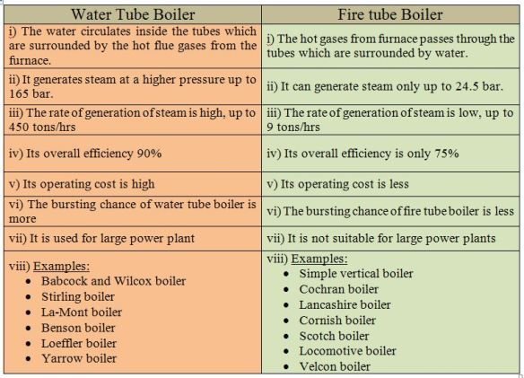
    Difference Between Water Tube Boiler And Fire Tube Boiler

    Difference between Water Tube Boiler and Fire Tube Boiler

    In today’s article we are going to learn about the difference between water tube boiler and fire tube boiler or in simple words Fire Tube Boiler Vs Water Tube Boiler

    We know that boiler is used onboard for power generation and it is one of the most important thing on ship.

    Boiler is broadly categorised into water tube boiler and fire tube boiler. And since they are categorised differently this means that there must be some differences between them either in functioning, maintaining, running or economical differences. This article is all about their differences.

    Difference between water tube and fire tube boiler

    Fire Tube Boiler Vs Water Tube Boiler

    Water Tube Boiler Fire Tube Boiler
    1. The water flows inside the tube and the hot combustion gases flows outside the tube.1. The hot gases flows inside the tube and the water is outside the tube.
    2. These are generally high pressure boiler ranging up to 70-100 Bar.2. These are generally low or medium pressure boiler up to 25 Bar.
    3. Faster rate of steam Production.3. Lower rate of steam Production.
    4. More efficient4. Less efficient
    5. These boilers are mostly externally fired.5. These are internally fired. The furnace is placed at one end of the Fire tube.
    6. Suitable for large scale power plants.6. Suitable for small scale power plants.
    7. Since the operating pressure is high, the risk of explosion is also high.7. Risk of explosion is less, as less operating pressure.
    8. Occupies less floor space.8. Occupies large floor space.
    9. Because of complexity, skilled person is required to operate.9. Less complex, less skill required.
    10. Easy to clean as it is externally fired10. Difficult to clean as internally fired.
    11. The shell diameter is less.11. The diameter of shell is more.
    12. Easy to carry out maintenance.12. Difficult to carry out maintenance
    13. Since water flows inside the tube, treatment of water is necessary to prevent deposit formation.13. Treatment of water is not necessary.
    14. More environment friendly14. Less environment friendly
    15. Operating cost is high15. Operating Cost is less.
    16. Examples: Babcock and Wilcox Boiler, Stirling Boiler, La-mont Boiler, Benson Boiler, Loeffler Boiler, Yarrow Boiler16. Examples: Simple Vertical Boiler, coachran boiler, Lancashire Boiler, Cornish Boiler, Scotch Boiler, Locomotive Boiler, Velcon Boiler.

    Difference between water tube boiler and fire tube boiler in a descriptive format | Fire Tube Boiler Vs Water Tube Boiler

    Fire Tube Boiler

    In fire tube boiler, as the name suggest Fire Tube (i.e Fire in Tube) the hot combustion gases ( flue gases) are passed through the tubes which are arranged inside the cylindrical drum and the outside of the tubes are surrounded by the water.

    The heat transfer takes place between the hot gases and the surrounded water through the tubes. This heats up the water and convert it into steam.
    Fire Tube boilers are simple in construction as compared water tube boilers and are used as their alternative because of being cheaper.

    These are generally used in small scale industries as the operating pressure of fire tube boilers are low.

    Other advantages of fire tube boilers are that they have compact size and have the ability to handle the fluctuations in steam demand more efficiently.
    There are also certain disadvantages of Fire tube boiler like it’s efficiency is low, it takes longer time to convert that amount of water into the steam, not able to cope up with sudden increase in load.

    Water Tube Boiler

    Now coming to the water tube boiler (i.e water in the tube), the water runs inside the tube and the hot gases are passed over the outer surface of the tube.

    The heat is transferred from the hot gases to the water in the tubes and it gets converted into steam.

    Since the steam is generated in the tubes , the water tube boilers can operate at higher pressure than the fire tube boilers and hence they are used in large scale production that requires high pressure and high steam output.

    Advantages

    Water tube boilers are generally provided with more than one burner and we can use these burner either individually or in parallel combination for a single furnace.

    This provides a way to have controlled shutdowns so that maintenance can be carried out without shutting off the boiler entirely.

    Also the burners can be used to operate at different loads.
    Water tube boilers are also provided with Programmable Logic Controller for controlling and maintaining proper functioning of the burners provided.

    They also control the super heater and feed water systems.
    As the volume of area of production of steam is less in water tube boiler the water tube boilers are able to produce high pressure steam and at a faster rate than the fire tube boiler.

    They can also produce super heated or saturated steam according to the design and the place where they are required. They are able to operate at higher pressure.
    The water tube boiler can be constructed to use high-ash fuels in conjunction with the soot blowers and proper Ash handling and flue gas cleanup equipment to maintain environmental regulations.

    Disadvantages

    Though we have seen the various advantages of the water tube boiler but there are certain disadvantages also.

    The capital cost of water tube boiler is very high and the size of the water tube boiler is large as compared to fire tube boiler which bring it to a point that it is mostly constructed on the site where it has to be used.
    Because of the use of control systems the complexity and it’s cost increases more.

    And for working on it a proper training is required.
    Now that we have seen the descriptive difference between water tube boiler and fire tube boiler.

    Now it is more easy to remember in point form rather than the description, though the description gives you a better understanding of the differences.

    People also ask

    Which is better fire tube boiler or water tube boiler?

    Between the two types of boiler, Water tube boilers are more significantly more efficient than fire tube.

    It will be clear you after reading following reasons :-

    1.Water converts into steam very Quickly. When the water flow through the tubes ,it is only surrounded by heat rather than the other way around.

    Since the tube holds less water than the tank of fire tube boiler so ,it takes less time to convert that water into steam and thus less consumption of fuel.

    The water tube boiler did the work of producing steam in as little as five minutes, compared to an hour or more for the fire tube boilers. As a result, fuel savings costs can be significant over time

    2.Water tube boilers require less water. By heating water in the tube via a once-through design, water tube boilers don’t need to store as much water to produce steam, making them more environmentally friendly by design.

    3.Water-tube boilers can adapt to change loads more easily. Water tube boilers can respond more quickly to changes in demand for steam, by heating less water at one time.

    Individual units configured modularly can power up or down as required. This means we only use fuel and water as needed, greatly reducing energy waste in the process.

    4.Water tube boilers seem to last longer. The ability to operate more effectively also ensures that boilers for water tubes have a longer life expectancy than their counterparts for fire tubes.


    Where are water tube boiler used ?

    Water tube boilers are most commonly used where high pressures of steam are required and may exceed 3,000 psi.

    Water tube boilers can generate saturated or superheated steam that is useful for applications such as steam turbine power generation. In addition, such boilers are commonly used in process industries, including chemical, refining and pulp and paper manufacturing.

    Why water tube boiler is more efficient than fire tube boiler ?

    In fire tube boilers, flue gases need to heat up a large amount of water and are therefore slow and inefficient.

    Because of their slow operation, more heat is lost to the surroundings. In the water tube boilers, flue gases pass through the water tubes and deal with less water.

    They’re fast in operation, therefore, and less heat is wasted in the surroundings.

    So, They’re more efficient.

    Why can’t a fire tube boiler be made with a high capacity as a water tube boiler ?

    Fire tube boilers are used for small capacity & less pressure boilers because the heat is explored to evaporate the water is less available also the heat is less available. But in the water tube Boilers area available to heat the water is more because the flue gas flows around the tubes. It is therefore used for higher capacity and high pressure of approximately 127 Kg/cm2 or more.

    What are the differences between a tank boiler and a water tube boiler?

    You may be referring to “Fire-tube” vs. “Water tube” In the former, the entire tank is filled with pressurized water and steam with fire flowing through the tank in pipes. This form is no longer used except in historic installations.

    Excessive pressure due to technological malfunction or operator error may cause the entire tank to burst, killing people nearby. The sort of water pipe will never explode because all the pressure is in the pipes and the tank has hot gases. If the tube splits, the steam spills harmlessly into the firebox.

    So these were some of the basic difference between Water tube Boiler and Fire tube Boiler which are covered in this article in tabular as well as descriptive form. Fire Tube Boiler Vs Water Tube Boiler is one of the common things that people generally ask. If You liked this article, please share it with your friends and give your feedback in the comment below.

    Check Out Other Important Topics

    Home

    IC Engine

    Electrical

    Important PDFs

    Boilers

    Synergy Maritime Exam

    Naval Arch

    Interview Questions

    Difference Between

    Types of Pumps

    Types of Valves

    MEO Class 4

    Auxiliary Machines

    What is Difference between pressure relief valve and pressure safety valve

    Difference between pressure relief valve and pressure safety valve: When discussing pressure in process industries, two important safety devices often come up: Pressure Safety Valves (PSVs) and Pressure Relief Valves (PRVs). While these terms are commonly used interchangeably, it’s important to understand that they have distinct differences, despite serving similar functions.

    Must Read: Difference between safety valve and relief

    Difference between Pressure Relief Valve and Pressure Safety Valve

    Here’s the information in a simple table format that compares the Pressure Safety Valve (PSV) and Pressure Relief Valve (PRV):

    CriteriaPressure Safety Valve (PSV)Pressure Relief Valve (PRV)
    Primary ApplicationUsed for compressible fluids or gasesUsed for liquids
    Opening MechanismOpens suddenly and completely when set pressure is reachedOpens gradually, proportional to the increase in pressure
    Manual OperationCan be opened manually with an easing gearCannot be opened manually
    Set PressureTypically just above working pressure (not more than 3% above)Generally 10% above working pressure
    Activation TypeInstantaneous full openingGradual opening
    UsageProtects gas-filled or compressible fluid vesselsProtects liquid-filled vessels

    This table format provides a clear, side-by-side comparison of the two types of valves.

    Pressure Safety Valves (PSV) vs. Pressure Relief Valves (PRV)

    If you’re interested in the detailed differences between these two, keep reading!

    Pressure Safety Valve (PSV)

    • Direct Activation: Opens instantly when the set pressure is reached.
    • Manual Operation: Can be opened manually using an easing gear.
    • Set Pressure: Typically just above the working pressure, not exceeding 3% above the approved working pressure.

    Pressure Relief Valve (PRV)

    • Proportional Activation: Opens gradually, in proportion to the increase in pressure.
    • No Manual Operation: Cannot be opened manually.
    • Set Pressure: Usually 10% above the working pressure.

    Key Differences Based on Operation

    • Pressure Safety Valve (PSV):
    • Primarily used for systems containing compressible fluids or gases.
    • Opens suddenly and completely once the set pressure is reached.
    • Pressure Relief Valve (PRV):
    • Typically used for systems containing liquids.
    • Opens gradually, in proportion to the increase in pressure.

    By understanding these differences, you can choose the right valve for your system and ensure optimal safety.

    Source; https://valvulasfevisa.com/know-the-difference-between-a-pressure-relief-valve-prv-vs-a-pressure-safety-valve-psv/


    Check Out Other Important Topics
    Home

    IC Engine

    Electrical

    Important PDFs

    Boilers

    Synergy Maritime Exam

    Naval Arch

    Interview Questions

    Difference Between

    Types of Pumps

    Types of Valves

    MEO Class 4

    Auxiliary Machines

    Difference between pv valve and pv breaker in tanker

    Difference between PV Valve and PV Breaker : The Pressure Vacuum (PV) Valve and the Pressure Vacuum (PV) Breaker are critical safety devices used on ships, especially on oil tankers, to regulate and maintain safe pressure levels within cargo tanks. While both devices play a role in preventing overpressure or vacuum conditions, they operate under different circumstances and serve different purposes.

    What is pressure vacuum (PV Valve ) and pressure vacuum (PV ) Breaker ?

    Pressure Vacuum (PV) Valve:
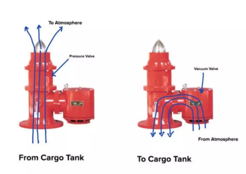
    A Pressure Vacuum Valve (PV Valve) is a device used to maintain a balanced pressure in a cargo tank during loading, discharging, or transportation of cargo. It ensures that the tank does not experience dangerous overpressure or underpressure conditions, which could potentially lead to ruptures or implosions. The PV valve opens when the tank pressure exceeds the safe limit or falls below a certain threshold, allowing gases to escape or air to enter, keeping the tank safe and intact.

    Pressure Vacuum (PV) Breaker:
    A Pressure Vacuum Breaker (PV Breaker) is a safety device installed in the inert gas (IG) line on a ship’s deck. It ensures that the pressure in the system stays within safe limits, preventing the buildup of excessive pressure or creating a vacuum condition in the IG line. This is important for protecting the cargo tanks and the ship’s structure from potential damage. The PV Breaker acts as a backup for the PV Valve, ensuring additional safety by breaking any excessive vacuum or pressure in the system.It is a safety devices which is used in IG Line on Deck.

    Function of pv valve and Pv breaker

    Here are the functions of both the Pressure Vacuum (PV) Valve and the Pressure Vacuum (PV) Breaker:

    Functions of PV Valve:

    1. Maintaining Pressure and Vacuum: The PV valve ensures that the cargo tank maintains a balanced pressure during loading and unloading operations.
    2. Preventing Overpressure: It releases excess pressure from the tank to prevent overpressure conditions, which could damage the tank.
    3. Preventing Underpressure: It allows air or gas to enter the tank to prevent underpressure (vacuum) conditions that could collapse the tank.

    Functions of PV Breaker:

    1. Handling Abnormal Pressure Increases During Loading: The PV breaker opens to relieve abnormal pressure increases when the gas outlet rate from the tank is insufficient during cargo loading.
    2. Handling Abnormal Pressure Increases During Discharge: When cargo is discharged at a higher rate than the inert gas blower can replace, the PV breaker prevents pressure buildup in the tank.
    3. Dealing with Breather Valve Malfunction: In case the breather valve fails to operate due to pressure fluctuations (caused by changes in atmospheric or seawater temperatures), the PV breaker steps in to stabilize the tank’s pressure, either releasing or admitting gas as necessary.

    Both devices are crucial for maintaining safe operating conditions within cargo tanks.

    Difference Between PV Valve and PV Breaker

    Let’s break down the key differences between the PV Valve and the PV Breaker from various points of comparison.

    Overview:

    The Pressure Vacuum (PV) Valve and the Pressure Vacuum (PV) Breaker are critical safety devices used on ships, especially on oil tankers, to regulate and maintain safe pressure levels within cargo tanks. While both devices play a role in preventing overpressure or vacuum conditions, they operate under different circumstances and serve different purposes. Let’s break down the key differences between the PV Valve and the PV Breaker from various points of comparison.


    Difference between PV Valve and PV Breaker:

    Point of ComparisonPV ValvePV Breaker
    FunctionMaintains safe pressure and vacuum in individual cargo tanks during normal operations such as loading and unloading.Handles abnormal increases in pressure or vacuum when the PV valve is unable to cope, providing backup for excessive pressure surges.
    LocationInstalled on each cargo tank individually.Installed on the inert gas (IG) line on the deck, serving all cargo tanks.
    Operating PressureOperates at 1400 mm of water column (0.14 bar) and vacuum of -250 mm of water column (-0.025 bar).Operates at 1600 to 1800 mm of water column (0.16 to 0.18 bar) and vacuum of 400 mm of water column (-0.04 bar).
    Primary RoleEnsures normal pressure control in the cargo tank during loading, discharging, and transportation.Acts as a safety backup when pressure or vacuum exceeds the PV valve’s capacity, preventing dangerous tank conditions.
    Handling Rate of LoadingHandles pressure adjustments during normal cargo loading and discharging rates.Handles rapid and abnormal increases in pressure due to fast loading rates or equipment failure.
    Response to VacuumOpens to let air into the tank if vacuum conditions occur, ensuring the tank doesn’t collapse.Operates when the vacuum exceeds the PV valve’s limits to protect the system from extreme vacuum conditions.
    Number of DevicesTypically, one PV valve per cargo tank.Typically, only one PV breaker per system, serving all tanks via the IG line.
    Design ObjectivePrimarily designed for normal operational safety.Designed to handle emergency situations when the pressure exceeds normal levels or when equipment (like the breather valve) malfunctions.

    On basis of operating pressure

    Based on the operating pressures measured in terms of water column (mm of water column):

    Pressure Vacuum (PV) Valve:

    • Operating Pressure:
    • The PV valve operates at 1400 mm of water column (which is approximately 0.14 bar).
    • It also operates at a vacuum of -250 mm of water column (approximately -0.025 bar). This means the valve opens to relieve pressure when it reaches 1400 mm water column and allows air in when the vacuum reaches -250 mm.

    Pressure Vacuum (PV) Breaker:

    • Operating Pressure:
    • The PV breaker operates between 1600 mm to 1800 mm of water column (which is approximately 0.16 to 0.18 bar).
    • It operates at a vacuum of 400 mm of water column (approximately -0.04 bar). The PV breaker is designed to activate when the pressure or vacuum exceeds the capacity of the PV valve, handling higher pressure surges or stronger vacuum conditions.

    Conversion Note:

    As a reference:

    • 1000 mm of water column ≈ 0.1 bar

    This helps in converting between pressure in mm of water column and bar as needed.Image

    Difference between PV Valve and PV Breaker

    When and where Pv breaker and pv valve is used

    Where and When PV Valve is Used:

    • Location: An individual PV Valve is installed on each cargo tank. It directly controls the pressure and vacuum within that specific tank.
    • Usage:
    • During loading and unloading operations, where pressure fluctuations can occur.
    • The PV valve automatically responds to minor pressure or vacuum changes in the tank. If the internal pressure drops below a certain level, the valve opens downward, allowing external air or gas to enter the tank. If the pressure inside the tank exceeds a certain limit, the valve opens upward, allowing gases to escape.
    • It works under normal operating conditions to maintain the balance between internal and external pressure.

    Where and When PV Breaker is Used:

    • Location: Typically, only one PV breaker is fitted in the inert gas (IG) line on the deck of the ship, servicing all cargo tanks through the IG system.
    • Usage:
    • The PV breaker is used in situations where there is an abnormal pressure increase that exceeds the handling capacity of the PV valve.
    • This occurs when cargo is loaded at a high rate, causing a rapid increase in pressure that could lead to an explosion if not relieved.
    • The PV breaker opens to relieve the excess pressure when the loading rate or inert gas blower is beyond the specified limit.
    • It also activates if there is a malfunction in the PV valve or breather valve, ensuring the safety of the cargo tanks.

    In essence, PV valves handle normal operational pressure adjustments, while the PV breaker acts as a safety backup for extreme pressure surges.

    What pressure it maintains

    The pressure ranges maintained by the PV Valve and PV Breaker are as follows:

    PV Valve:

    • Pressure Range:
    • For large oil tankers, the PV valve typically maintains the tank pressure between 0.07 to 0.20 bar.
    • It ensures that minor pressure fluctuations are controlled, keeping the tank pressure within this range during normal operations like loading and unloading.

    PV Breaker:

    • Pressure Handling:
    • The PV breaker is designed to handle pressure surges beyond the capacity of the PV valve.
    • It activates if the pressure rises to 0.24 bar (maximum), relieving the excess pressure and preventing any damage to the cargo tanks.

    In summary, the PV valve handles normal pressure regulation, while the PV breaker comes into play when the pressure rises abnormally, ensuring safety beyond the operational limits of the PV valve.

    Summary

    • The PV valve manages everyday pressure and vacuum conditions within each cargo tank, ensuring safe operations during cargo loading and unloading.
    • The PV breaker steps in during emergency situations when pressure or vacuum conditions become abnormal, acting as a secondary safeguard for the entire cargo system.

    Also Read : Bearing Temperature Detector

    You Can Read More About It On, https://www.quora.com/unanswered/What-is-the-difference-between-a-PV-breaker-and-a-deck-seal-on-a-tanker-vessel

    Check Out Other Important Topics

    Home

    IC Engine

    Electrical

    Important PDFs

    Boilers

    Synergy Maritime Exam

    Naval Arch

    Interview Questions

    Difference Between

    Types of Pumps

    Types of Valves

    MEO Class 4

    Auxiliary Machines