Bevel gears are a special types of gears that have been used to transfer rotational motion between intersecting shafts for many years. From automobiles to industrial machinery, they are frequently used in a variety of applications.
We will go deep into the world of bevel gears in this comprehensive guide, looking at their characteristics, varieties, uses, applications, advantages and disadvantages. This article is for everyone who is interested in the fascinating world of gears, whether they are mechanical engineers, hobbyists, or just plain curious.
What Is Bevel Gears
A Bevel Gears are types of gears used for transferring shaft power or mechanical energy between shafts which are intersecting, either at an angle or perpendicular.
The simple definitions of a Bevel Gear is a cone-shaped gear which is used for transmitting power between 2 intersecting axels.
These gears are gears in which the axes of the two shafts intersect and the gears’ tooth-bearing faces are conically shaped. These gears are mostly fitted or mounted on shafts which are perpendicular or 90 degree to each other, but it can be designed to use at other angles as well.
These gears are used to transfer mechanical energy from linear to vertical shafts.
Bevel Gear Examples
Geometry And terminology
To better understand gears and gear systems, one must first understand the vocabulary. The following are some of the terminology used to describe gears and their tooth profiles. These are relevant to all sorts of gears, not only bevel gears.
Pinion :
When meshing pair of gears, the smaller gear is called a pinion gear.
Gear
When meshing pair of gears, the larger gear is called a gear.
pitch
Pitch, often known as circular pitch, is the distance between one point on a tooth and the equivalent point on the adjacent tooth on the same gear.
Pitch diameter
The pitch circle’s diameter. This is a predetermined design parameter that determines other gear properties including tooth thickness, pressure angles, and helix angles.
Diametral pitch
The ratio of the number of teeth and the pitch diameter.
Pitch angle
It is angle between the face of the pitch surface and the shaft axis.
pitch surface
The imaginary truncated cone wherein the base diameter is the pitch circle.
Pressure Angle
A preset value described by the angle between the meshing teeth’s line of force and the pitch circle’s line at the contact point. To mesh, gears must have the same pressure angle. For straight bevel gears, the ideal pressure angle is 20°.
Shaft angle
It is the angle between driven and driver shaft.
Addendum
It is defined as the upper outline of the gear teeth.
Dedendum
The bottom outline of the gear teeth.
Addendum angle
It is the angle between the pitch surface and the face of the teeth’s upper surface, or top land.
Dedendum angle
the angle between the pitch surface and the bottom of the teeth, also known as the bottom land.
Space with taper
The change of the space width along the face, measured on the pitch surface.
Thickness Taper
The change of tooth thickness measured on the pitch surface
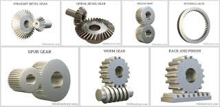
Bevel Gear Types
On the basis of teeth of gears , it is classified as straight, spiral or “zerol”.
- Straight
- spiral
- Zerol
- Hypoid
- Miter
Read More : Types of Bevel gear
Straight bevel gear
These are types of gear which have teeth that are straight and parallel to the cone’s generators. As the name suggests, they have straight teeth and resemble a spur gear, except that they are conical rather than cylindrical. The teeth are in a straight line that intersects at the axis of the gear when extended.
Spiral
The teeth of this types of gears are spiral in shape, i.e curved or oblique. Due to curved and oblique orientation of teeth, cause more overlap between teeth, it promote gradual engagement and disengagement upon tooth contact. This helps in smoothness. This improves smoothness, minimal vibration and noise produced during operation. Also, because of higher load sharing from more teeth in contact, spiral bevel gears have better load capacities. This allows them to be smaller compared to straight bevel gears with the same capacity.
The advantages of this gears is the larger thrust load exerted, which requires more expensive bearings.
Zerol Bevel Gear
It has teeth that curve longitudinally. In terms of profile, these gears are similar to spiral bevel gears. The spiral angle distinguishes them; Zerol kinds have 0° spiral angles, while spiral types have 35°.
Hypoid Bevel Gears
This is the type of gear in which the axes of the shafts are not intersecting nor parallel.
The offset is defined as the distance between the two gear axes. Hypoid bevel gear teeth are helical, comparable to spiral bevel gear teeth. A helical bevel gear is a hypoid bevel gear with no offset. Hypoid gears are manufactured and shaped similarly to spiral bevel gears.
Miter Bevel Gear
This is a bevel gear with a 1:1 gear ratio, which means that the driver and driven gears have the same number of teeth. Because a mitre gear provides no mechanical benefit, its function is confined to shifting the axis or rotation. Mitre gears often have axes that intersect perpendicularly. The shafts in some assemblies are oriented to intersect at any angle. These are referred to as angular mitre bevel gears. Angular mitre bevel gear shaft angles can range from 45° to 120°. Straight, spiral, or Zerol mitre bevel gear tooth cuts are available.
bevel Gear Characteristics
Bevel gears use two conical forms of toothed wheels to transfer energy between axes that are cut inside the same space; hypoid gears, on the other hand, can transmit energy between two axes that cross each other.
A bevel gear’s teeth can be spiralled or straight, which is also known as a conical helix. Several types of gears can be defined not only by the width of their teeth, but also by the width of the tooth face or the circular pitch of the centre.
Bevel gear features includes:
1. Strong chemical resistance and corrosion resistance
2. Noise reduction and shock absorption
3. Long life, high load bearing capacity
4. Light weight and low cost
5. Easy to mold, good lubricity
Some of advantages discussed below:
Advantages Of Bevel Gears
These gears are a common choice in many industries because they have many advantages over other types of gear mechanisms. Let’s look into a few of the major Advantages:
- Efficient Power Transmission: These types of gears are superb at transmitting power between intersecting shafts, ensuring minimal power loss and high efficiency in the gear assembly.
- Compact Design: Their conical shape allows this types of gears to operate in tight spaces, making them suitable for applications with limited room for gear mechanisms.
- Versatility: It can be manufactured in a wide range of sizes, ratios, and configurations, enabling their use in diverse applications and machinery.
- Smooth Operation: Spiral bevel gears, in particular, offer exceptionally smooth and precise operation, minimizing noise, vibrations, and wear on the gear assembly.
- High Load Capacity: These are designed to withstand heavy loads, making them ideal for demanding applications that require robust and durable gear mechanisms.
- Easy Installation and Maintenance: These are relatively easy to install and maintain, allowing for efficient operation and reduced downtime in industrial settings.
Disadvantages of bevel Gears
- Complex Manufacturing Process: The manufacturing process of bevel gears is more complex compared to other gear types. The conical shape of the gears requires precise cutting and machining techniques, which can increase production time and costs.
- Higher Cost: Due to the complexity of their manufacturing process, These gears tend to be more expensive than other gear types. The additional machining steps and specialized equipment required contribute to the higher cost.
- Limited Load-Carrying Capacity: It has a lower load-carrying capacity compared to some other gear types, such as spur gears. The tooth engagement area is limited to the outer edge of the gear, reducing the amount of contact and load distribution.
- Efficiency Losses: It can experience higher friction and efficiency losses compared to other gear types. The sliding contact between the gear teeth can result in energy losses through heat and vibration, reducing overall efficiency.
- Sensitive to Misalignment: These are sensitive to misalignment between the input and output shafts. Even slight misalignment can lead to increased wear, noise, and decreased performance. Proper alignment and regular maintenance are crucial to mitigate this issue.
- Limited Ratios: These gears are not as versatile in terms of gear ratios compared to some other gear types. The available gear ratios may be limited, particularly for certain applications requiring specific speed and torque requirements.
- Increased Noise and Vibration: Bevel gears, especially straight bevel gears, can generate higher noise and vibration levels compared to other gear types. The sliding contact between the teeth can produce noise, which may require additional measures for noise reduction in certain applications.
Applications of Bevel Gears
Bevel gears are widely used in various industries and applications due to their versatility and efficiency in transmitting power between intersecting shafts. Some of the important applications of bevel gears are ;
- Automotive Industry: These are extensively used in the automotive industry for power transmission in differentials, axle drives, and steering systems. They enable the transfer of power and torque smoothly and efficiently, ensuring the proper functioning of the vehicle.
- Aerospace: These are utilized in aerospace applications, such as aircraft engines and landing gear systems. They help control and transmit power in complex mechanical systems, ensuring precise movements and reliable operation.
- Marine Industry: These are essential components in marine propulsion systems, including ship engines and thrusters. They allow for the efficient transfer of power from the engine to the propeller, enabling smooth and controlled vessel movements.
- Industrial Machinery: These find extensive use in various industrial machinery, such as machine tools, printing presses, and textile machinery. They play a vital role in transmitting power and controlling speed, ensuring the proper functioning of these machines.
- Power Generation: These are employed in power generation applications, including wind turbines and hydroelectric plants. They help transfer power from the rotor to the generator, enabling the conversion of mechanical energy into electrical energy.
- Mining and Construction: These are utilized in heavy machinery used in mining and construction, such as excavators, loaders, and cranes. They provide the necessary torque and power transmission required for these demanding applications.
- Medical Equipment: These are employed in various medical equipment, including surgical robots, imaging systems, and prosthetic devices. They enable precise movements and efficient power transmission in these critical healthcare applications.
- Defense and Military: These types of gears find applications in defense and military equipment, such as tanks, artillery systems, and naval vessels. They play a crucial role in transmitting power and controlling movements in these high-stakes scenarios.
- Robotics: These are widely used in robotics for joint mechanisms and motion control systems. They allow for smooth and precise movement of robot arms and other robotic components, ensuring accurate and efficient operation.
- Home Appliances: These are utilized in various home appliances, including washing machines, mixers, and food processors. They help transfer power from the motor to the rotating components, enabling the desired functions of these appliances.
Reference :