Oily Water Separator : Construction, Working Principle, How it Works ?

An Oily Water Separator is machine which is used on ship for separating oil from oily water mixtures and from the emulsion.

In this article we are going to learn about Oily Water Separator, its working principle, Troubleshooting faults and very important how to solve faults.

And very important is that, this device is used on ship to separate oil from water. A small amount of oil discharged in sea water creates problems to chief engineer.

Oily Water Separator Working Principle

Must Read: Purifier

What is Oily Water Separator ?

The oily water separator (OWS) is a very important piece of equipment / device carried on board to separate the mixtures of oil and water into their separate components.

An oily water separator is used to treat the oil – water mixture from bilge spaces , oil in any compartment in the ship which has accumulated water ,before discharging into the sea.

Purpose of Oily Water Separator

Oily water separator is used on ship to prevent the discharge of oil overboard mainly when pumping out Bilges. ( When de ballasting or cleaning oil tanks ).

On Which Principle Oily Water Separator Works

Oily water separator Works on the Principle of Seperation – Gravity Differential between the oil and water.

Why we use Oily Water Separator ?

1. Because free oil and oily emulsions discharge in the water way can interfere with the natural process such as photosynthesis and re-aeration and induced the destruction of algae and plankton so essential to fish life .

2. Inshore discharge of oil can cause damage to birds life and Mass pollution of beaches .

Ships found discharging water containing more than hundred milligram per litre of why lord is charging more than 60 litre of oil for nautical mile can we have fined.

Must Read: Fresh Water Generator


Differences between Oily Water Separator and Centrifuge Purifier


-Oily water separator are required to handle large quantity of water from which usually a small amount of wall must be removed

-centrifuge are required to remove usually a small quantity of water from much larger amount of of oil

additionally the centrifuge must separate solids and it must with respect to fuel handle large quantity at the rate at which the fuel is consumed

Suggested Read: Air Compressor

Oily Water Separator Working Principle or Principle of operation :

The fundamental principle of separation by which oil / water separators work is the difference of gravity between oil and water.

The oil exists in oily water mixtures as a collection of globules of various sizes.

The force acting on such a globule which causes it to move in the water is proportional to the difference in weight between the oil particle and an equal volume water particle.

The resistance to movement of the globule depends on its size and the the fluid viscosity.

In the case of small particles moving under streamline flow conditions, the relationship between these properties can be expressed in Stoke ‘s Law.

Stroke ‘s law

Stokes law states that force that returns a sphere moving through a viscous fluid under streamline flow or laminar flow is directly proportional to the velocity of the sphere diameter of the sphere viscosity of the fluid

it is expressed as,

Fr=3πvud

Fr=resistance to movement

v= terminal velocity of particle

u= viscosity of road

d=diameter of particle

The separation of oil from oil/ water mixture only when separating force and terminal force equal.

In general , a high separation rate is encouraged by the large size of the oil globule, the elevated system temperature (which increases the specific gravity differential of oil and water and reduces the viscosity of the oil) and the use of seawater.

Turbulence or agitation should be avoided as it causes the oil to be mixed and re-entrained.
Laminar or streamlined flow is beneficial for good operation of OWS.

In addition, the heating coils provided to improve separation.

There are several other means used for improving and speeding up the operation.

The oil / water separator entrance area is large so that the flow is slow and large oil slugs can move quickly to the surface.

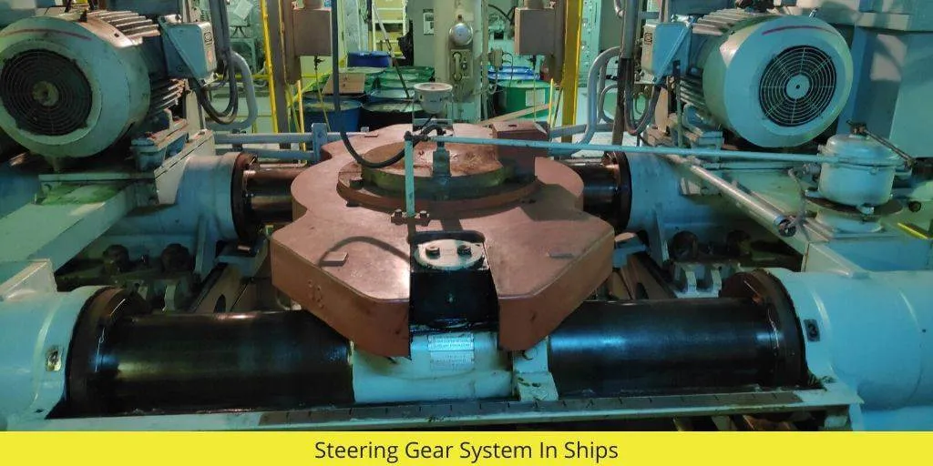
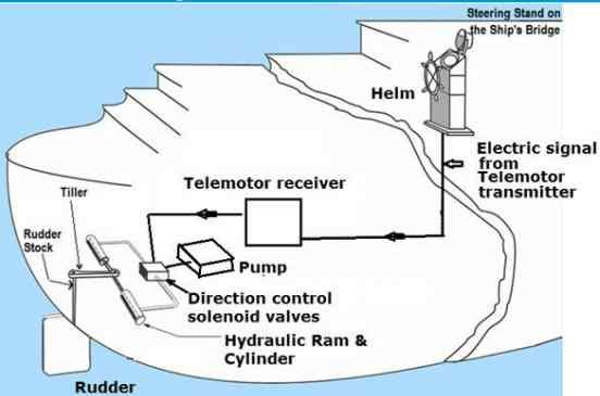
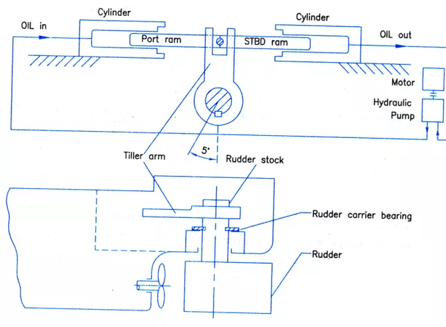
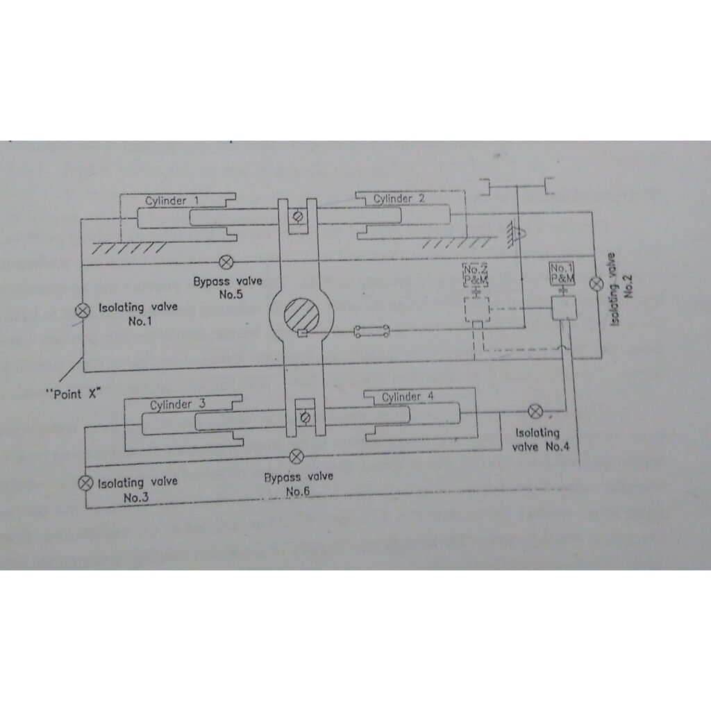
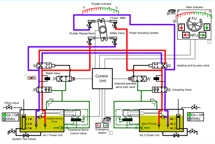
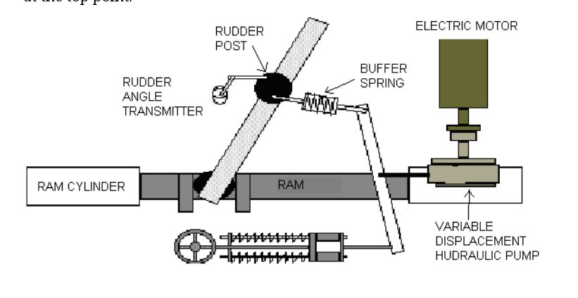
Suggested Read: Steering Gear

Oily Water Separator Working

How does an oily water separator work?

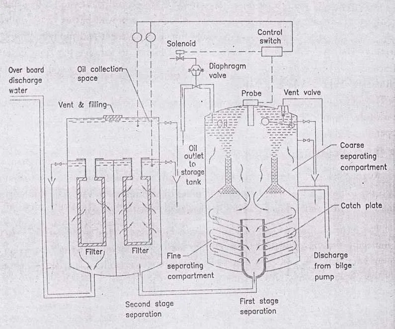
The complete unit is filled with clean water and after that the oil / water is pumped to the first stage of the coarse separating compartment. Here, oil with a lower density than water will rise to the surface with the aid of heating coils in this process. It’s known as a collection space.

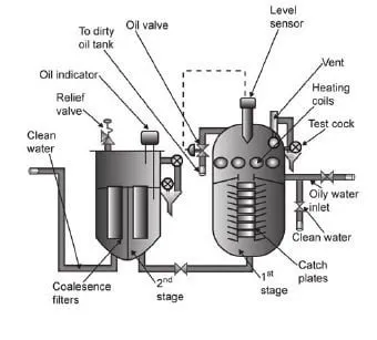
A sensor then senses the oil level and the oil is then dumped (according to ppm ) to the dirty oil tank via an oil valve.

The remaining oil – water mixture moves down to the fine separation compartment and moves slowly between the catch plates.

On the underside of these plates,more oil will separate and move outwards until it is free to rise up to the collection space.

And then ,Almost oil free water passes on to the second stage of the unit.

In the second stage, two coalesce filters are situated. The first filter removes any physical impurities present and promotes some filtration, the 2nd filter uses coalesce filter elements to achieve final filtration.

Clean water then leaves the 2nd stage on to a clean water holding tank or via a 15ppm monitor with audible and visual alarms overboard.

Coalescence :- Breakdown if surface tension between the oil droplets in an oil-water mixture which causes them to join and increase in size.

Suggested Read: filter

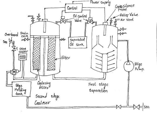
Working and Construction

lt is the operation of an oily water separator with a fifteen ppm monitor. The separation of fine water in the separated fixed place in two stages, in the first stage of separation is by gravity whereas in the second stage the separation is by coalescing filter.

Oily water separator mainly consists of 3 units

  1. Separator unit
  2. Filter unit
  3. control unit (oil content monitoring)

A. Separator Unit

This unit consists of catch plates which are inside a coarse separating compartment and an oil collecting chamber.

The boost pump delivers clean sea water to the first stage of the separated through the inlet valve.

The vent is kept open till all the air is removed from the seperator;the oily water mixture is then pumped through the separator inlet pipe into course separating compartment .

Here, because of its lower density, some oil can separate and rise into the oil collection spaces.

The remaining oil-water mixture now flows down into the fine separating compartment and passes gradually between the catch plates.

More oil can separate on the underside of these plates and travel out until the oil-collecting space is free to rise.

Almost oil-free water passes through the central pipe and leaves the separator unit. The purity at this point will be hundred parts per million or less.

An automatically operated valve releases the oil into a storage tank.

(The oil drain valve from the top of the first stage separated is a diaphragm controlled piston valve control air and supplied to the diaphragm through for the solenoid operated pilot valve, the capacitance probe senses oil quantity in the collection space and energizes the form allied to the control switch, was a passive downwards from the first to the second phase coalesce the two central pipe)

Air is released from the Unit By A Vent valve .

Steam or electric heating coils are provided in the upper and sometimes the lower part of the separator, depending upon the type of oil to be separated. (heating reduces viscous drag of oil and thus makes separation of oil and water Easier)

where greater purity is required the almost oil free water passes to a filter unit,the water flow in turn through two filter stage and the oil removed passes to oil collecting spaces.

The first stage filter removes physical impurities present and promotes some points fine separation.

2.The Filter Unit

This is a separate unit whose input comes from the discharge of the first unit.
● The unit consists of three stages – the filter stage, the coalescer stage and the collection chamber.

● The impurities and the particles are separated by a filter and settled down to the bottom for removal.

The second stage filter uses coalescer inserts for final de-oiling.

Coalescence is the breakdown of surface tension between oil droplets in and oil water mixture which causes them to join and increase in size.

Coalscer filter

Oil content of the final discharge is the last thing ppm,in case the discharge of water after the second stage is more than fifteen ppm .

The monitor synthesis and gives an audible and visual alarm in the engine room,at the same time the monitor and the signal to a three way valve on the overboard discharge line which closes the overboard and opens to be those tanks.

The sensor reports the normal operation, once the oil content drops below fifteen between the test cocks can be used to ascertain the levels of oil and water manually.

The oil from the collecting spaces is drained manually, as is usually required, about once a week.

Filter inserts will require a change in the period of useful life, depending on the operating conditions.

3. Oil Content Monitoring Unit

Regulations on the discharge of oily water, set a concentration limit of ,up to 15 parts per million.

A monitor is required to measure these values and to provide both continuous recordings and alarms where the level allowed is exceeded.
The principle used is that of ultra-violet fluorescence.

This is the emission of light by a light-absorbing molecule.

Energy is lost during the short time between absorption and emission, and light of a longer wavelength is emitted. Oil fluoresces more readily than water, so this provides the means to detect it.
A sample is drawn off from the overboard discharge and passes through sample cell (Figure ).

The ultraviolet light is directed to the sample and the fluorescence is monitored by a photoelectric cell.

The measured value is compared to that of the maximum desired value in the controller / recorder.

When an excessive level of contamination is detected, the alarm is sounded and the diverting valve is operated.

The discharging liquid is then passed to a slop Vault.

Alarms and shutdown

If the 15 ppm oil content monitoring device detect discharge of oil content over 15 ppm,it shuts the unit down and activates the alarm. But in some cases only alarm is there.

Oily Water Separator Requirements

1.As per MEPC 107(49), a bilge alarm or an Oil Content Control unit, which provides for an internal recording of alarm conditions, must be certified by an approved organization.

2.The OCM equipped with the oily water separator must be tamper-proof.

3. When freshwater is used for cleaning or zeroing purposes, the OCM must trigger and sound an alarm.

4.Separator capable of achieving 15 ppm on type C emulsion

Reason for improper functioning of and Oily Water Separator

1. The principle of separation of Oily water separator on which the separator function is the gravity differential between oil and water.

The force acting on oil Globule to move in the water is proportional to the difference in weight between the oil particle and a particle of water of equal volume.

The resistance to the movement of globule depends on its size and viscosity of the fluids.

Thus in general, a High rate of separation is favoured by

  • large size of globule.
  • elevated temperature of the system *which affects both of specific gravity differential of the oil and water and the viscosity of the water) And the use of seawater

2. Pumping Consideration

Since the rate of separation depends on the oil Globule size it will be appreciated that any disintegration of oil globules in the oily feed to the separator should be avoided and this factor can be seriously affected by the type and rating of the pump used.

A large number of bilge pumps are centrifugal and often they are used as a supply pump for the separator.

Thus, Charan the supply and produce small oil droplets which dispersed throughout the water, which in turn ma y seriously affect the separation effectively

A positive displacement pump for example slow running double vane, screw, reciprocating or gear pump enables a much better performance to be achieved from the separator as they do not produce large quantity of a small droplets. using pump after the separator may give a discharge having less than 15 PPM concentration without using 2nd Stage filters.

From above two points it is evident that even if the separator is well maintained and correctly operated following factors can cause improper functioning of the separator.

  1. Throughput of the separator is excessive
  2. excessive rolling and pitching of the ship causing disintegration of wall globules.
  3. pump type or and rating is not matching causing too much of turbulence.
  4. Turbulence caused due to pumping rate.

Further Read:

In this Article, I have written answers to all Questions arises on the Topic Oily Water Separator which I have learned from my faculty or from books.

Anything I missed ? Please write it down in the comment section and don’t forget to share it, because sharing is caring.

FAQ ( Frequently Asked Questions )

What is the purpose of an oily water separator?

It’s Purpose is used to separate Oil from mixture of oil and water. It is used on ship to prevent from making impure sea water. Directly discharge of oily water in sea cause pollution and damage to life of birds and sea animals.

What are the types of oily water separator?

1. Coalescing plate oil water separators treat water to ~10 ppm oil content.
2. Hydrocyclone oil water separators treat water to ~5 ppm oil content.
3. Vertical gravity oil water separators water to ~50 ppm oil content.

What are the three segments of oily water separator?

1. Separator Unit
2. Filter Unit
3. Oil Monitoring Control Unit

Check Out Other Important Topics

IC EngineImportant PDFsBoilersSynergy Maritime ExamNaval ArchMEO Class 4
Interview QuestionsDifference BetweenTypes of PumpsAuxiliary MachinesTypes of ValvesHome

Wikipedia

Lubrication in 4 four stroke engine with diagram

How lubrication in 4 stroke engine Takes place ? It is done either by splash lubrication or Pressure lubrication system. In this article, I will describe step by step so that you can understand Lubrication in 4 four stroke engine ( auxiliary engine ) with diagram engine easily.

Try to understand the layout Lubricating system of 4 stroke or Auxiliary engine.It help you in visualising all the parts and how oil moves from sump to all parts and come back to sump of the engine.

Suggested Read : Types of Lubrication

Layout of Lubricating system of 4 stroke or Auxiliary engine

Here is description of the lubrication system for a four-stroke engine highlights the key processes involved in ensuring the efficient functioning of engine components. Here’s a more structured breakdown of the layout and operation of the four-stroke engine’s lubricating system:

Lubricating System Overview:

The lubricating system of a four-stroke engine typically uses a wet sump lubrication system, where oil is stored in a sump located at the bottom of the engine. A lube oil pump, powered by the engine itself, circulates the lubricating oil through the engine’s various components in a closed loop.

lubrication in 4 four stroke engine

Key Components and Process Flow:

1.Lube Oil Sump: The oil is stored in the sump located at the bottom of the engine. The sump holds the oil and acts as the source from which the lubricating oil pump draws oil.

2.Lube Oil Pump: The lube oil pump is driven by the engine and is responsible for circulating oil throughout the system. It pumps oil from the sump and directs it through the rest of the system.

3. Primary Filter: After being drawn from the sump, the oil first passes through a primary filter, which removes larger particles and impurities from the oil, ensuring cleaner oil flows through the system.

4. Oil Cooler: After filtration, the oil passes through an oil cooler, which reduces the temperature of the oil, ensuring that it can efficiently lubricate engine components while preventing overheating.

5. Main Filter: The oil then passes through the main filter for final filtration, removing any remaining impurities.

6. Oil Distribution: After passing through the cooler and main filter, the oil splits into two separate lines:

  1. Lubricating Main Bearings and Crankshaft:
    • One line directs oil to the main bearings. From there, oil passes through holes in the crankshaft, reaching the crankpin for lubrication.
    • The oil continues inside the crankshaft, moving toward the piston pin (gudgeon pin) for lubrication. The lubricated piston pin ensures the smooth movement of the piston inside the cylinder.
  2. Lubricating Cylinder Liners:
    • Through the end of the gudgeon pin, oil also lubricates the cylinder liners, ensuring minimal friction between the piston and the cylinder walls.
    • Scraper rings on the piston remove excess oil from the cylinder liner, directing it back to the sump.

7. Lubricating Gear System: The second line from the main filter goes to lubricate the engine’s gear system, which includes various pumps and components attached to the crankshaft.

  • Components like the lube oil pump, jacket water pump, governor, rocker arm pump, and fuel oil pump are all lubricated from this line to ensure smooth operation.

Key Lubricated Components:

  • Main Bearings: Support the crankshaft, allowing it to rotate smoothly.
  • Crankshaft and Crankpin: Transmit the engine’s power; lubrication is critical to reduce wear due to friction.
  • Piston Pin (Gudgeon Pin): Connects the piston to the connecting rod, needing lubrication for smooth piston movement.
  • Cylinder Liners: The inner walls of the cylinder where the piston moves up and down; lubricated to reduce friction and wear.

Piston Cooling (To be Discussed Later):

  • In addition to lubricating the engine components, the lube oil system also plays a role in piston cooling, where oil circulates through or around the piston to regulate its temperature. You plan to explain this further in a future section.

Line Diagram of 4-stroke engine lubricating system

Lubricating oil from the oil sump tank >>> Primer filter >>> The lubricating oil pump >>> lubricating oil cooler >>> lubricating oil pressure relief valve >>> lubricating oil filter >>> lubricating oil main pipe.

Now lubricating oil main pipe branched into two lines :-

1. The one line lubricates the main bearing shell, crank pin bearing shell and piston pin bush.

2. While the other line lubricates the cam shaft bearing shell, tappet surroundings, governor and idle gear bush.

Then they will come together to drop into the sole plate. In some modes of engines, the valve rocker arm is lubricated in this circulation.

Pressure Type Lubrication System

This system ensures that all critical engine parts receive continuous lubrication, minimising wear and tear, reducing friction, and preventing overheating of components.

Here, a provided an in-depth explanation of the pressure-type lubrication system in a four-stroke engine, focusing on the key parts that require lubrication to ensure smooth engine operation. Here’s a clearer breakdown of the components and their lubrication process: …

The above see that lubrication system is pressure type lubrication system. Now we see all the parts which is used for lubrication. The main parts which is lubricated are :-

  • Main Bearings
  • Crank Pin or Bottom end bearings
  • Top end bearings or Gudgeon pin Or piston pin
  • Cylinder liner lubrication
  • Camshaft
  • Crankshaft drive
  • Governor drive
  • Turbocharger
  • Rocker arm system

Components and Lubrication Details:

  1. Main Bearings:
    • The main bearings support the crankshaft and are connected to the connecting rod. Due to the heavy loads they bear, proper lubrication is critical to reduce wear and ensure smooth motion.
    • Lubrication Process: Lube oil, under pressure from the lube oil pump, passes through holes in the bearings to provide continuous lubrication.
  2. Crank Pin Bearings (Bottom End Bearings):
    • These bearings connect the crankshaft to the crank pin, allowing the conversion of reciprocating motion (up and down movement of the piston) into rotary motion.
    • Lubrication Process: The oil is transferred from the main bearing through an internal passage in the crankshaft, which delivers the oil to the crank pin bearings.
  3. Gudgeon Pin (Piston Pin) or Top End Bearings:
    • The gudgeon pin connects the piston to the connecting rod, experiencing reciprocating motion. Proper lubrication is critical to prevent friction between the piston and the connecting rod.
    • Lubrication Process: Oil is delivered to the gudgeon pin through passages inside the crankshaft, continuing the flow from the crank pin.
  4. Cylinder Liner Lubrication:
    • The cylinder liner forms the sliding surface for the piston. Lubrication here is necessary to reduce friction between the piston and the liner.
    • Lubrication Process: Oil from the gudgeon pin passes through the end of the piston pin and reaches the cylinder walls. Scraper rings on the piston distribute the oil over the liner, while excess oil is scraped back into the sump.
  5. Camshaft:
    • The camshaft drives the operation of various pumps and other engine components by controlling the timing of the valve operation (inlet and exhaust valves).
    • Lubrication Process: A nozzle is provided on top of the camshaft, where oil is sprayed to lubricate the gears involved in the camshaft’s operation.
  6. Crankshaft Drive:
    • The crankshaft drive also requires lubrication, particularly in the areas where gears are involved in transmitting power to other components.
    • Lubrication Process: A nozzle sprays oil onto the gear meshes to ensure proper lubrication and reduce friction.
  7. Governor Drive:
    • The governor controls the engine’s speed by regulating fuel delivery based on load conditions.
    • Lubrication Process: The governor mechanism is lubricated via oil delivered through a dedicated piping system to the gear mesh, ensuring smooth operation.
  8. Turbocharger:
    • Some engines use the same lube oil system to lubricate the bearings of the turbocharger. The turbocharger has two main bearings: the turbine-side bearing and the blower-side bearing.
    • Lubrication Process: A branch of the lube oil system is used to deliver oil to both bearings, ensuring proper lubrication for the high-speed rotating shaft of the turbocharger.
    • Alternative Lubrication: In some engines, splash lubrication is used for the turbocharger bearings. The bearings dip into the oil in the sump, allowing them to be lubricated as they rotate.
  9. Rocker Arm System:
    • The rocker arm controls the opening and closing of the inlet and outlet valves, and its lubrication is essential for smooth valve operation.
    • Lubrication Process: In some engines, the rocker arm system is lubricated by the same lube oil pump. After passing through the filters, one oil line branches off to lubricate the rocker arm.

Special Pump: In Daihatsu diesel engines, a special rocker arm pump (internal gear pump) is provided exclusively for lubricating the rocker arm system, offering precise control of lubrication in this area.

Line diagram of rocker arm system

Lubrication of rocker arm system are explained below :-

The Rocker arm lube oil tank >>> torchoid pump ( with safety valve ) >>> lube oil filter >>> Supply oil main pipe >>> rocker arm shaft bush >>> rocker arm end >>> returning main pipe >>> rocker arm lube oil tank

Rocker Arm Lube Oil Tank:

This tank stores the lubricating oil specifically for the rocker arm system. It is separate from the engine’s main lubrication system to ensure that the oil remains clean and free from contamination.

Torchoid Pump (with Safety Valve):

The torchoid pump is responsible for pressurizing and pumping the lubricating oil from the tank. The safety valve ensures that oil does not exceed safe pressure levels, protecting the system from damage.

Lube Oil Filter:

After the oil is pumped, it passes through a lube oil filter, which removes contaminants and impurities. This step is crucial for maintaining the quality of the oil used for lubrication.

Supply Oil Main Pipe:

The filtered oil travels through the supply oil main pipe to reach various lubrication points in the rocker arm system.

Rocker Arm Shaft Bush:

The oil first reaches the rocker arm shaft bush, providing lubrication to the bushings that support the rocker arm’s pivot point.

Rocker Arm End:

The oil then flows to the rocker arm end, where it lubricates the contact points responsible for actuating the engine’s valves.

Returning Main Pipe:

After lubricating the rocker arm, the oil returns through the returning main pipe to be recirculated back into the rocker arm lube oil tank.

Rocker Arm Lube Oil Tank (Return):

Some oil returns directly to the rocker arm lube oil tank from the oil pressure relief valve located at the end of the supply oil main pipe. This valve allows excess oil to be returned to the tank, preventing overpressure in the system.

Line Diagram of 2-stroke engine lubricating system

Lubricating oil from the oil sump tank >>> Primer filter >>> The lubricating oil pump >>> lubricating oil cooler >>> lubricating oil pressure relief valve >>> lubricating oil filter >>> lubricating oil main pipe.

Now lubricating oil main pipe branched into two lines :-

1. The one line lubricates the main bearing shell, crank pin bearing shell and piston pin bush.

2. While the other line lubricates the cam shaft bearing shell, tappet surroundings, governor and idle gear bush.

Then they will come together to drop into the sole plate. In some modes of engines, the valve rocker arm is lubricated in this circulation.

Lubricating Oil pump :- lubricating oil pump used here is external gear pump. It is located at the front of the engine and is powered by the crankshaft via a coupling or a gear wheel.

Note :- In some engine splash lubrication system is used. In this lubrication system, lube oil is submerged partially. when crankshaft rotates, it splash the lube oil on surfaces.

How piston cooling is done in 4 stroke engine ?

As piston get hot too much because it is directly in contact with combustion. So, we need to to cool it working properly. Otherwise failure of Piston. Piston cooling is done by the Nozzle provided near the under space of piston.

This is all about lubrication of 4 stroke engine or auxiliary engine.

FAQ ( Frequently Asked Questions )

Which type of lubrication system is used in stroke engine?

 type of lubrication system used as a dry-sump type, wet-sump type, force-feed type, or splash type.

Check Out Other Important Topics

IC EngineImportant PDFsBoilersSynergy Maritime ExamNaval ArchMEO Class 4
Interview QuestionsDifference BetweenTypes of PumpsAuxiliary MachinesTypes of ValvesHome

Steering Gear in Ship Working, Types, Diagram, Regulations

What is Steering Gear ?

Steering gear is the system used on ships to control the direction of the vessel. It allows the ship to turn from port (the left side) to starboard (the right side), or from starboard to port, while it is moving during sailing.

Important Note: The steering gear only works when the ship is in motion. It does not function when the ship is stationary.

Steering Gear In Ship

Capacity

For optimal performance, a steering gear system must have the capacity to rotate the rudder from 35° port to 35° starboard. Additionally, it should be able to transition the rudder from 30° on one side to 35° on the other side within 28 seconds. This ensures quick and efficient maneuvering of the ship.

Limitations and Efficiency of Steering Gear
One important limitation to note is that the steering gear operates effectively only when the ship is in motion. When stationary, the system will not function properly, making it crucial for navigation during active sailing.

Must Read : Fresh Water Generator

Main Parts of Steering Gear

The main components of a ship’s steering gear system are crucial for controlling the rudder and, by extension, the ship’s direction. Here are the key components:

1. Rudder: The rudder is the primary component responsible for changing the ship’s direction. It is mounted at the stern and moves side-to-side to steer the vessel.

2. Steering Gear Motor : This motor powers the entire steering system, providing the necessary force to move the rudder. It can be hydraulic or electro-hydraulic.

3. Hydraulic Pump: In hydraulic systems, the pump generates pressure to actuate the rudder’s movement. It is essential for providing smooth and controlled rudder operations.

4. Control Unit : The control unit is responsible for receiving signals from the bridge (via the steering wheel or autopilot) and converting them into actions for the steering gear.

5. Ram (Actuator) : The ram or actuator converts the hydraulic or mechanical force from the steering gear motor into movement to turn the rudder.

6. Telemotor : The telemotor transmits steering commands from the ship’s bridge to the steering gear unit, using hydraulic or electrical signals.

7. Steering Gear Transmission Linkages : These mechanical linkages connect the control unit to the rudder stock, ensuring precise movement of the rudder as commanded by the bridge.

8. Rudder Stock : The rudder stock is the shaft that connects the rudder to the steering gear. It transmits the movement from the steering gear to the rudder.

9. Hunting Gear : A feedback device that monitors the position of the rudder and ensures it aligns with the helm’s position, helping to correct any deviations automatically.

10. Relief Valve : A safety component that prevents excessive pressure build-up in the hydraulic system, protecting the system from damage.

These components work together to ensure the ship can steer effectively and safely.

Main Components of Steering Gear System

Main Components of Steering Gear System

In the steering system, the steering gear provides a movement of the rudder In response to a signal from the bridge.

3 main parts of steering gear system

a) Control Equipment :- Control equipment convey a signal of desired rudder angle from the steering flat where it is received to activate the power unit and transmission system until the desired angle is reached.

b) Power Unit :- power unit provides the force when required & with immediate effort to move the rudder to the desired angle.

c) Transmission Unit to the Rudder Stock :- Transmission system (steering gear) is the means by which the movement of the rudder is accomplished.

Note :- Control equipment can be hydraulic control equipment ( known as telemotor ) or an electrical electronic control equipment.

The steering control (Tele-motor transmitter) on the navigation bridge which sends electrical signals to the Tele-motor receiver in the ship’s steering gear room.

This Tele-motor receiver in the steering gear room sends electrical signals to the Direction control solenoid valves.

What are the Types of Steering Gear used on Ship?

1) Electro-hydraulic system

a) Ram type system ( 2 ram or 4 ram)

b) Vane type system

2) All electric system a) Ward Leonard system b) Single motor system

Types of Hydraulic Powered Transmission Unit or Steering Gears

It is of two types :-

a) Ram type ( may be 2 ram or 4 ram )

b) Rotary vane type

Here we will Discuss About Ram Type Steering Gear System

Ram Type Steering Gear System Working

Working

If the oil is pumped into the LHS (port) hydraulic cylinder and drawn from RHS ( starboard) hydraulic cylinder, there will be a left to right sliding movement of the rams. Through the RAM cross head, the tiller arm will move towards starboard and the rudder towards port .

The instant pumping is stooped , movement of tiller arm will stop and rudder will be hydraulically locked in this new position as oil now has no way to leak and is fully blocked within the ram cylinders and vice – versa.

Two Ram Steering Gear Working

Sketch shows the arrangement of a 2 Ram the steering gear.

Two Ram Steering Gear System

When the steering wheel is turned signal goes to telemotor receiver through the telemotor transmitter which operates the hunting gear.

Hunting gear int urn Moves the variable delivery pump (hele shaw or swash plate type ) operating spindle from neutral position.

Thus pump start pumping to one hydraulic cylinder and from the other hydraulic cylinder, oil is sucked to pump. And the Ram starts moving and this movement is transmitted through the tiller to the rudder stock and rudder.

The movement of rudder cause the hunting gear to move in such a way that once the desired angle of rudder is reached the pumps operating spindle comes back to neutral positions, and no further pumping & rudder remains in desired angular position.

4 Ram Steering Gear Working

Above Diagram shows the arrangement of a four ram steering gear.

4 Ram Steering Gear System in Ship

Working

As the signal from the telemotor system operates the hunting gear it actuates the variable delivery pumps to pumping position,thus oil flows to two numbers diagonally opposite cylinder ( say 1 and 4 ) from other two cylinder (two and three ) oil is sucked into the pump.

This causes the rudder to turn in clockwise direction. If due to the action of telemotor system hunting gear is moved to other direction then oil will be supplied to cylinder 2&3 and from 1& 4 oil will flow into the pump and thus the rudder turns in anticlockwise directions.

Turning of the rudder will move the hunting gear in such a way that so that once the desired position is reached , pump operating Lever will bring the pump into neutral position and the desired rudder position will be maintained.

Each cylinder is fitted with cylinder isolating valve. There are two bypass valve and relief valve connecting cylinder 1 and 2 & cylinder 3 and 4.

In case of excessive pressure in the cylinder ( which may occur due to shock on the rudder )

The spring loaded bypass valve will open automatically causes the connected cylinder to bypass.

Replenishing tank is provided into the system to make up any loss of Hydraulic oil .

Safety Arrangements in a Steering Gear System on Ship

A) Isolating valve :- isolating valves are provided at each cylinder & Rotary vane number which when closed it will hold the rudder by trapping the oil in the Chambers.Pumps are also equipped with an isolating valves so that the pump can be totally shut off from the circuit and removed for servicing while the steering is continued with the other pumps.


B) Bypass valve:-. Bypass valves are normally closed but can be opened on two cylinder gear to allow for the use of emergency steering.One pair of cylinder can be bypassed on a four cylinders – gears while the other pair of cylinders provide emergency steering at reduced torque.


C) Relief valves :- relief valves are provided between complementary pair of cylinder or Chambers of vane gears. They are set to lift at pressure above the normal maximum.


D) Shock valves are fitted in pipework of the system between cylinders to prevent excessive shock load from the rudder due to heavy seas being transmitted to the hydraulic system.

What are the Safety Devices for Steering System

Safety Devices are

  1. Hunting gear
  2. Buffer spring
  3. Angle adjusting stop (Hand over position limit switch)
  4. Double shock valve
  5. Relief valve
  6. Tank level alarm (oil)
  7. Over load alarm

How does a ship steering gear work ?

The ‘control force’ for turning is triggered off the wheel at the helm, which reaches the steering system. The steering system generates a torsional force at a certain scale, which is then, in turn, transmitted to the steering gear that rotates the steering wheel.

What is Emergency Steering ?

The emergency steering system, as the name suggests, is a system that is used during the failure of the ship’s main steering system.
A situation can occur in which the remote control operation may fail to work and their can be a sudden loss of steering control from the bridge. This can be due to sudden power failure, any electrical fault in the system or the control system which includes faulty tele-motor or servo motor which is used for transferring the signal from bridge to the steering unit.

An emergency steering system is used to control the steering of the ship in such an emergency situation by manually measuring it from inside the steering gear room.

Steering Gear in Ship


Wikipedia

Frequently Asked Questions ( FAQ )

What is the purpose of steering gear?

Its purpose to turn the ship from port to starboard and Vice-versa. Its purpose in car to turn the wheel.

What are the 3 main parts of steering gear system?

The main parts are Transmission , power unit and Control Unit.

What are the 2 types of steering systems?

1.Hydraulic and 2. Electrohydraulic

What is Steering Ram ?

The steering ram, also known as the steering cylinder, is the most important part of a hydraulic steering system. To ensure proper and precise operation, choose an appropriate steering ram for your application.

What is Follow up and Non follow up Steering system ?

Follow up : – This is the standard steering method, which includes steering angle feedback to the helm. This can be operated manually or automatically.
The ship’s heading can be programmed into the autopilot, which can then compare it to the desired heading and adjust the rudder angle accordingly.

Non Follow Up– Normally used only for backup purposes. Each steering gear unit has a single lever; by moving the lever in one direction, the rudder begins to turn; the rudder continues to turn until the lever is released or it reaches the limit of its operation.

What Do You Call Someone who Steers a Ship ?

A helmsman or helm is a person who steers a ship, sailboat, submarine, other type of maritime vessel, or spacecraft.

Why is Steering Test rudder angle 35 Degree to 30 degree ?

It is because the point at which it is reached can be exactly judged as it crosses 30 degree. And As hunting gear puts pump stroke to zero, the rudder movement slows down progressively as it approaches 35 degree.

Steering gear safeties

What are Steering Gear Safeties ?

Steering gear safeties are mechanisms integrated into the steering gear system to protect the vessel’s steering mechanism from potential damage, ensure safe operation, and alert the crew to any issues. These safeties are critical for both hydraulic and electrical systems, ensuring the steering gear operates within safe limits.

Categories of Steering Gear Safeties:

  1. Hydraulic Safeties
  2. Electrical Safeties

Hydraulic Safeties:

  1. Level Switch: Monitors the hydraulic oil level in the tank, triggering low-level and low-low-level alarms.
  2. Relief Valve: Prevents overpressure in the hydraulic system by releasing excess pressure.
  3. Manual Bypass Valve: Allows manual override or bypass of the hydraulic system in case of failure.
  4. Low-Pressure Valve: Alerts if hydraulic pressure drops below safe operating levels.
  5. High Lube Oil Temperature Cut-Out: Shuts down the system if lubrication oil temperature exceeds safe limits.
  6. Low-Level Cut-Out: Shuts down the hydraulic system if the oil level falls below a critical point.

Electrical Safeties:

  1. Electrical and Mechanical Stopper for Rudder: Prevents the rudder from moving beyond safe limits.
  2. Electrical Motor Overload Alarm: Warns if the steering motor is drawing excessive current.
  3. Power Failure Alarm: Alerts the crew in case of a loss of power to the steering system.
  4. High Temperature Alarm: Triggers if electrical components overheat.
  5. Self-Starting after Power Failure: Automatically restarts the steering gear after a power outage.
  6. Short-Circuit Trip: Cuts power to the system in the event of a short circuit.
  7. Phase Failure Alarm: Detects loss of one or more phases in a three-phase electrical supply.
  8. 200% Insulation in Motor: Ensures the motor has double insulation for added protection.

Other Safety Devices for the Steering System:

  • Hunting Gear: Used to reduce oscillations in the steering gear system.
  • Buffer Spring: Helps to absorb shock and prevent mechanical damage.
  • Angle Adjusting Stop (Hand Over Position Limit Switch): Limits rudder movement to prevent damage.
  • Double Shock Valve: Provides protection against hydraulic shock in the system.
  • Relief Valve: Prevents overpressure in the hydraulic system.
  • Tank Level Alarm (Oil): Alerts when oil levels in the hydraulic tank drop.
  • Overload Alarm: Warns of excessive load on the steering gear system.

These devices work together to ensure the safe and efficient operation of the steering system, helping prevent malfunctions and protecting the vessel from potential hazards.

Follow me on Twitter

Tappet Clearance Inlet and Exhaust Pdf, Tool, Adjustment

Tappet clearance is a crucial aspect of vehicle engine maintenance that should not be ignored. It refers to the clearance or gap between the camshaft and valve in an engine. It plays a significant role in ensuring optimal engine performance and longevity. Regular tappet clearance adjustment can prevent engine damage, increase fuel efficiency, and reduce engine noise.

Without adequate tappet clearance, there is a risk of valve damage and potential harm to the engine. Therefore, it is necessary to maintain the appropriate clearance to keep the vehicle running smoothly. In this article, we will provide you with a comprehensive guide on tappet clearance, its purpose, and the importance of regular maintenance. We will also discuss how to check and adjust the valve tappet -clearance and the common signs of tappet- clearance issues.

What is Tappet clearance?

Tappet clearance is the small gap between the rocker arm and the top of the valve stem (Yoke).  It is an important factor in determining the timing and duration of valve opening and closing, which affects engine performance and efficiency.

Tappet Clearance

Some Other Definitions are mention below :

It is nothing but a gap between the rocker arms and the point where they rest on the stem of valves. These Both surfaces are flat.

Note :- It is also known as valve lash (in some book ).

Conditions for Tappet clearance?

It can be only adjusted when the valves are closed and the engine is cooled during the compression stroke. It is taken when the inlet and outlet valves are in closed position & engine at the cooled condition at the compression stroke.

When Tappet Clearance of Inlet and exhaust Valve is taken ?

As with any engine maintenance task, checking tappet clearance should be done at particular intervals or when certain conditions arise. To ensure that the engine valve mechanism performs optimally, tappet clearance must be inspected and adjusted according to the following conditions:

  • According to running hours mentioned in the engine manual. Running hours depend on the types of engine. , model or size: Checking tappet clearance after every running is recommended. This interval can vary depending on the make and model of the vehicle, so it’s essential to consult the owner’s manual to determine the right maintenance schedule. Regular inspections can prevent significant damage and expense down the line.
  • Unusual engine noise: Abnormal engine noises, such as clicking or ticking sounds, can indicate that the tappet clearance is not correct. A quick inspection can help diagnose the problem before it becomes more serious.
  • Engine overheating: If the engine overheats frequently, it can cause wear and tear on the engine’s components, including the valve mechanism. In such cases, it’s wise to check the tappet clearance and adjust it if necessary.
  • Low engine compression: Low engine compression can lead to poor acceleration, fuel economy, and other performance issues. It’s essential to check the tappet clearance in such cases as incorrect clearance can cause compression loss.

By keeping an eye out for these conditions and adhering to the set maintenance schedule, you can ensure proper tappet clearance and optimal engine performance.

Tappet Clearance Purpose ?

The purpose of Tappet Clearance is to allow some mechanical expansion and lengthening of the valve stem and push rods when the engine warms up.

The primary function of tappet clearance is to allow for a small expansion gap between the valve stem and pushrods to accommodate the effects of a heated engine.

If this is not done, the valve will not sit properly as the engine heats up. As previously stated, this could eventually result in power loss, engine irregularities, and other issues.

why tappet clearance is required ? Why it is Required ?

The requirement of clearance is answered as, to maintain correct timing ( change in clearance will lead to an early or delayed opening of the inlet or exhaust valves ).

Note :- It needs to be adjusted for proper opening and closing of valves of the diesel engine.

The valve is one of the most critical parts of the engine. It controls the flow of air and fuel into the engine and the exhaust gases out of the engine. The valve opens and closes by the movement of the rocker arm, which is connected to the camshaft. Tappet clearance affects the valve operation by controlling the timing and duration of valve opening and closing.

  • Timing: Tappet clearance plays a crucial role in determining the timing of valve opening and closing. The correct tappet clearance ensures that the valve opens and closes at the right time, allowing the engine to operate efficiently.
  • Duration: The duration of the valve opening and closing is also affected by tappet clearance. The appropriate clearance ensures that the valve stays open for the right amount of time, allowing enough air and fuel to enter the engine.

Therefore, maintaining the correct tappet clearance is essential for optimal engine performance and longevity. It helps ensure that the engine runs smoothly, efficiently, and with minimal wear and tear.

In simple, it is required to maintain proper timing of opening and closing of valve without any delay or early inlet opening.

Effect of Incorrect Tappet Clearance of Exhaust Valve

Having incorrect tappet clearance in a vehicle’s engine can lead to a host of issues affecting the overall performance and longevity of the engine. Let’s take a look at some of the effects that can result from improper tappet clearance:

  • Valve Damage: Insufficient tappet clearance can cause the valves to remain partially open, leading to overheating and ultimately damaging the valves.
  • Decreased Engine Performance: Incorrect tappet clearance can reduce engine power and torque output, resulting in poorer overall performance.
  • Increased Fuel Consumption: When tappet clearance is too tight, the engine has to work harder to operate, resulting in increased fuel consumption and higher expenses for the vehicle owner.
  • Noisy Engine: When tappet clearance is too loose, it can cause the engine to produce a knocking or ticking sound, which can be annoying and an indication of a more severe underlying problem.

It is essential to maintain the correct tappet clearance to avoid these issues and ensure that your vehicle’s engine operates smoothly and efficiently for as long as possible.

What Will Happen if Tappet Clearance Less :-

If the clearance decreases– The valve will open early and close late.

The valve will open sooner and close later if the clearance decreases. This is due to the rocker arm remaining connected to the valve for an extended period of time. We get a larger contact area between the valve stem and rocker arm with less clearance. As a result, the rocker arm pushes the valve down for a longer period of time, keeping the valve open for longer.

  1. Valve will open early and close lately.
  2. Air induced in combustion chamber for combustion through an inlet valve may leak out. So, less air will be available for combustion.
  3. Power of the engine will be reduced.
  4. Fuel consumption by engine will increase, and engine may become unbalanced and the exhaust temperature will be very high.
  5. The valve may remain open, in worst conditions, resulting in loss of compression pressure of the engine, burning of the exhaust valve and increase in turbocharger fouling.

What will happen if Tappet clearance is more :-

If the clearance increases– The valve will open late and close early.

If the clearance increases, the valve will open slowly and close quickly. Because there is more clearance, the contact area between the valve stem and rocker arm is smaller. As a result, the valve remains open for a shorter period of time but closed for a longer period of time (which explains the delayed opening).

  1. The valve will open lately and close early.
  2. It reduces the maximum lift of the valve.
  3. Less heat energy to the turbocharger of engine, cause reduction in the scavenge air and hence power decrease.
  4. There is no proper removal of the exhaust gas.
  5. Hammering of the v/v stem cause damage to the valve stem.
  6. It causes noise and eventually damage the working surface.

How to check Tappet clearance ?

Tappet Clearance is checked by using feeler gauge by putting in between the space of rocker arm and the Space where valve stem sit.

Checking the tappet clearance is a crucial part of engine maintenance. It ensures that the valve is opening and closing at the correct time, and the engine is running smoothly. Here is a step-by-step guide on how to check the tappet clearance:

  1. First, make sure the engine is cool before checking the tappet clearance. This will prevent any damage to the components.
  2. Locate the valve cover and remove it from the engine.
  3. Locate the camshaft, which is responsible for opening and closing the valves, and the rocker arm, which pushes on the valve stem to open and close the valve.
  4. Identify the valve that needs to be checked and find the corresponding rocker arm. Use a wrench to loosen the lock nut on the rocker arm.
  5. Insert a feeler gauge between the rocker arm and the valve stem. The feeler gauge should be a tight fit but not too tight that it cannot be inserted. Measure the clearance by noting the thickness of the feeler gauge.
  6. If the clearance is too tight or too loose, adjust it by tightening or loosening the lock nut on the rocker arm. Recheck the clearance to ensure it is within the manufacturer’s recommended specifications.
  7. Repeat the process for each valve in the engine.
  8. Once all the valves have been checked, replace the valve cover and start the engine. Listen for any abnormal noises or vibrations. If everything sounds normal, you have successfully checked the tappet clearance!

Regularly checking the tappet clearance can prevent issues such as valve damage and poor engine performance. It is recommended to check the tappet clearance every 10,000 miles or as specified by the manufacturer.

How to Know Which Unit is at TDC?

To check clearance, first sure that the unit you are going to check should be in Top Dead Centre ( TDC ).

The position of piston is At TDC checked by

  • The flywheel marking 
  • The fuel pump mark 
  • The checking the camshaft fuel 
  • The valve cam position.

If it is not at TDC then we use turning gear to make that unit at TDC. ( Note :- During turning make sure that indicator cock is open ).

Usually, there are 6-8 units in four stroke engines. So at the same time, the flywheel will show two units at TDC.

To make sure that particular unit is on the compression stroke and not at the power stroke, you can turn the push rods of both units by hands to check.

The one with free push rods is the one which is at compression stroke and the one with tight push rods is at power stroke.

So avoid the one which is at power stroke.

Now you need good filler gauges of different thickness.

Now gently try to push these filler gauges between the clearance of valve and rocker arm.

You may have to try different thickness. Just check in the manufacturer manual as for how much standard clearance should be.

Now you know that your clearance is less or more

How to Adjust Valve Tappet clearance / Adjustment Procedure

Prepare the following tools for Checking and Adjusting Tappet clearance of Valve :-

Feeler gauge of different thicknesses.

Tappet clearance inlet and exhaust valve
Valve head clearance adjusting the procedure

Adjusting the valve tappet clearance requires precision and careful attention. Here are the steps to follow:

  1. Start by removing the valve cover from the engine. This will expose the valves and valve springs.
  2. Rotate the engine until the camshaft lobe for the valve you wish to adjust is facing upwards.
  3. Insert a feeler gauge between the valve stem and the rocker arm. You should feel a slight drag when sliding the gauge back and forth.
  4. If the clearance needs adjustment, use an appropriate wrench to loosen the lock nut on the rocker arm and turn the adjustment screw until you achieve the desired clearance. Typically, the clearance specs can be found in the vehicle owner’s manual.
  5. Once the clearance is set, hold the adjustment screw in place and tighten the lock nut to secure the adjustment. Double-check the clearance with the feeler gauge to ensure it matches the desired specification.
  6. Repeat these steps for all the valves you need to adjust.
  7. Once you finish the adjustment, replace the valve cover and all other components you removed earlier.

Remember, precise measurements and adjustments are essential for optimal engine performance. If you are unsure or lack experience, it is best to consult a professional mechanic to perform tappet clearance adjustments.

Note:- When you move filler gauges while adjusting for particular clearance, you should be able to slide it smoothly (not too tight and not too loose ).

Importance of Regular Tappet Clearance Maintenance

Maintaining the proper tappet clearance is essential for the optimal performance and longevity of a vehicle’s engine. Regular maintenance of the tappet clearance should be a part of every vehicle’s maintenance schedule. Neglecting this maintenance can lead to numerous issues, such as decreased engine performance and fuel efficiency, increased engine noise, and in severe cases, valve damage or engine failure.

By incorporating tappet clearance maintenance into your regular vehicle maintenance routine, you can prevent these issues and ensure your engine runs smoothly. Periodic tappet clearance adjustments and inspections can help to optimize fuel efficiency, reduce engine noise, and extend your engine’s lifespan. Additionally, regular maintenance can save you money in the long run by preventing costly repairs due to engine damage resulting from neglected maintenance.

Make sure to consult your vehicle’s owner manual for the recommended tappet clearance maintenance schedule. Regular maintenance will keep your engine running smoothly, protect your investment, and provide a more enjoyable driving experience.

Common Signs of Tappet Clearance Issues

Regular maintenance of tappet clearance is crucial for optimal engine performance. Failure to maintain the correct clearance can lead to various engine problems. Here are some common signs that may indicate tappet clearance issues:

  • Excessively loud or unusual engine noises, especially when accelerating or idling
  • Inconsistent or rough engine performance, including misfires or hesitation
  • Decreased fuel efficiency
  • Increased engine vibrations or shaking

If you observe any of these signs, it is important to check the tappet clearance as soon as possible. Ignoring these symptoms can lead to more severe engine damage and costly repairs. Regular inspection and adjustment of tappet clearance can prevent these issues from occurring in the first place, ensuring smooth engine operation and prolonged engine life.

Tools and Equipment for Tappet Clearance Adjustment

Adjusting the tappet clearance in a vehicle’s engine requires specific tools and equipment to ensure accurate measurements and adjustments are made. Here are some of the essential items needed:

  • Feeler Gauges: These are used to measure the tappet clearance accurately. They come in different thicknesses, depending on the clearance required for a particular engine.
  • Wrenches: Different types of wrenches, such as a socket wrench or an adjustable wrench, may be needed to access and adjust the tappets.
  • Screwdriver: A flat-head screwdriver may be necessary to adjust the tappets, depending on the engine’s design.
  • Valve Cover Gasket: The valve cover gasket must be removed to access the tappets, and a new gasket is essential when reassembling the engine.
  • Shop Towels: It is crucial to keep the engine clean during the adjustment process. Shop towels can be used to wipe any excess oil or debris that may be present.

When performing tappet clearance adjustment, it is essential to follow the manufacturer’s instructions and guidelines carefully. It is also important to take necessary safety precautions, such as wearing gloves and protective eyewear.

Overall, having the right tools and equipment for tappet clearance adjustment is crucial in maintaining a vehicle’s engine performance and longevity. Regular maintenance and adjustments can prevent costly repairs and ensure optimal engine efficiency.

Tappet Clearance Tool

The valve tappet clearance is measured by

A. Vernier Calliper

B. Feeler gauge

C. Screw Pitch Gauge

D. Engineering Scale

Ans :- B. Feeler gauge

what is Tappet clearance

Tappet clearance refers to the small gap or space between the engine valve and the tappet, which is a component that helps control the valve operation. It is an essential adjustment that ensures smooth and efficient engine performance.

How much is tappet clearance?

It’s value is such that does not affect the the engine performance. The clearance taken is typically between 0.2mm and 0.6mm, depending on the inlet and exhaust valves and engine manufacturer.

Why is tappet clearance important?

Tappet clearance is necessary to prevent valve damage, optimize fuel efficiency, and reduce engine noise. Incorrect tappet clearance can lead to various engine problems, which can be costly to repair.

What is the purpose of tappet clearance?

The purpose of tappet clearance is to control the timing and duration of valve opening and closing. It allows for proper fuel combustion, optimal power delivery, and helps prevent valve damage. Maintaining the correct clearance ensures efficient engine operation and prolongs the engine’s lifespan.

Why is tappet clearance necessary?

Tappet clearance is necessary for several reasons. It helps prevent valve damage by ensuring the valve closes completely and does not contact the piston. Correct clearance also optimizes fuel efficiency by promoting proper combustion. Additionally, it reduces engine noise by preventing valve striking and improves overall engine performance.

When should tappet clearance be checked?

Tappet clearance should be checked under specific conditions or situations. It is recommended to check it during routine engine maintenance, after a significant change in engine temperature, if abnormal engine noise is detected, or after certain running hours. Checking tappet clearance regularly helps identify any necessary adjustments.

What are the effects of incorrect tappet clearance?

Incorrect tappet clearance can lead to various issues. If the clearance is too tight, the valve may not fully close, resulting in poor compression and power loss. On the other hand, too much clearance can cause noisy valve operation, reduced engine performance, and increased fuel consumption. It is crucial to maintain the correct clearance for optimal engine function.

How do I check tappet clearance?

To check tappet clearance, you will need a feeler gauge and a service manual for your specific vehicle. Start by removing the valve cover, locate the tappets and valves, and follow the manual’s instructions to measure the clearance using the appropriate gauge. It is important to perform this task with the engine at the correct temperature and in the recommended sequence outlined in the manual.

How do I adjust valve tappet clearance?

Adjusting valve tappet clearance requires precision and following the manufacturer’s guidelines. Typically, it involves loosening the locknut and using a wrench or screwdriver to adjust the clearance to the recommended specification. After adjustment, tighten the locknut to secure the setting. It is crucial to recheck the clearance after completing the adjustment.

What are the common signs of tappet clearance issues?

Common signs of tappet clearance issues include excessive engine noise, ticking or clicking sounds, decreased power, rough idling, and poor fuel economy. If you notice any of these symptoms, it is advisable to have your tappet clearance checked and adjusted if necessary to avoid further engine complications.

What tools and equipment are needed for tappet clearance adjustment?

To adjust tappet clearance, you will typically need a feeler gauge, a wrench or screwdriver for locknut adjustment, and a service manual specific to your vehicle. It is also recommended to have a clean workspace, gloves, and safety glasses for protection during the adjustment process.

Check Out Other Important Topics

IC EngineImportant PDFsBoilersSynergy Maritime ExamNaval ArchMEO Class 4
Interview QuestionsDifference BetweenTypes of PumpsAuxiliary MachinesTypes of ValvesHome

Also Read : Bearing Temperature Detector

Wikipedia

Understanding the Various Parts of a Ship: A Detailed Guide

Ships, whether for transporting goods or people, are intricate machines requiring a sophisticated combination of design, engineering, and construction. Understanding the various parts of a ship is crucial to ensuring smooth navigation and safe transport.

The anatomy of a ship consists of multiple parts, each with its distinct purpose and function. These parts include the hull, superstructure, propulsion system, navigation and communication equipment, cargo handling equipment, safety equipment, electrical systems, and plumbing and sanitation systems. Knowing how each of these components works is essential in comprehending the ship’s anatomy, construction, and systems.

From the bow to the stern, ships’ parts come in various shapes, sizes, and materials. The design and construction of the vessel must consider its purpose, route, and intended use. Every component plays a vital role in the ship’s overall functionality, stability, and efficiency.

As we explore these ship parts and systems in detail, you will gain a better understanding of how they work together to ensure smooth maritime navigation and efficient transport of goods and people. So, let’s dive into the fascinating world of ship anatomy and construction!

Parts of Ship

Ship Hull

The ship hull is the main body of the vessel that provides buoyancy and stability. It is the outermost layer and is responsible for withstanding the forces of the sea. The hull is made up of several components that work together to form a rigid and durable structure.

Hull Structure

The hull structure is made up of the bottom, sides, and deck of the ship. The bottom of the hull is called the keel, which runs the length of the ship and provides support and stability. The sides of the hull are called the plating or shell and are made of steel or aluminum to withstand the harsh marine environment. The deck is the top of the ship and provides a surface for crew and cargo.

Hull Components

The bow of the ship is the front and is designed to cut through the water efficiently. The stern is the back of the ship and provides propulsion and steering. The rudder, which is attached to the stern, provides directional control. The propeller is also attached to the stern and provides the force needed for movement. The hull also contains various openings such as hatches, vents, and portholes for access and ventilation.

Ship Superstructure: The Brain and Housing of the Vessel

A ship’s superstructure is the upper part of the ship above the main deck, which includes the bridgedeckhouse, and accommodations for the crew and passengers. It serves as the brain and housing of the vessel, containing essential systems and equipment necessary for safe and efficient navigation.

The Bridge

The bridge is the command center of the ship and is located at the front of the superstructure. It provides a panoramic view of the ship’s surroundings and serves as the primary control station for navigation, communication, and maneuvering. The bridge is equipped with essential instruments such as radarGPS, and compasses, which provide real-time data on the ship’s position, speed, and direction.

The Deckhouse

The deckhouse is the main living quarters for the crew and is located behind the bridge. It provides sleeping quarters, a galley, mess hall, and other amenities necessary for the crew’s comfort and well-being during long voyages. The deckhouse may also house other equipment and systems, such as the ship’s fire control center and emergency equipment storage.

Accommodations

The accommodations area is located towards the rear of the superstructure and includes cabins or living quarters for the crew and passengers. These quarters can range from shared rooms to private suites with en-suite bathrooms. The area also includes common areas such as lounges, recreational areas, and medical facilities.

The ship’s superstructure is critical in providing a safe and comfortable environment for the crew and passengers during long voyages. It is also responsible for housing and protecting the essential systems and equipment necessary for navigation, communication, and other ship operations.

Propulsion System

One of the most essential systems onboard a ship is the propulsion system, which provides the necessary power to move the vessel through the water. The propulsion system consists of various components, including the engine roompropellers, and engines.

Engine Room

The engine room is typically located in the lower part of the ship and houses the ship’s engines, generators, and other machinery. It is a critical area that requires constant monitoring and maintenance to ensure the ship’s smooth operation. The engine room is also where the crew can perform repairs and maintenance on the ship’s machinery.

Propellers

Propellers are essential components of a ship’s propulsion system, generating the force that moves the vessel forward or backward. The number and size of the propellers vary depending on the ship’s size and design, and they are typically located at the stern of the ship.

Engines

The type of engine used in a ship depends on the ship’s size, speed, and power requirements. Common types of engines include diesel engines, steam turbines, and gas turbines. They are typically located in the engine room and are responsible for generating the power to turn the propellers and move the ship through the water.

Parts of a ship Diagram

Navigation and Communication Equipment

Navigation and communication equipment are critical systems on any ship, ensuring safe navigation and effective communication with other vessels and shore.

One of the most important pieces of navigation equipment on a ship is radar, which uses radio waves to detect nearby objects. The radar system consists of a transmitter, receiver, and display screen, and it is used to detect and track other vessels and obstacles on the water.

GPS (Global Positioning System) is another essential tool for navigation. It uses satellites to determine a ship’s exact location and provides information such as speed, direction, and distance to other locations.

Communication equipment on a ship includes radios, which allow for communication with other vessels and shore stations. In addition, a ship’s communication system may include satellite phones, email, and other forms of electronic communication.

Most ships also have a bridge navigation system, which integrates radar, GPS, and other navigation tools into a centralized display. This allows for easier navigation and better situational awareness for the ship’s crew.

Risk Management

Effective navigation and communication are critical components of risk management on a ship. By using radar, GPS, and other tools, a ship’s crew can avoid collisions with other vessels and hazards such as reefs and rocks. In addition, effective communication can be the key to obtaining assistance during an emergency.

For these reasons, navigation and communication equipment are among the most important systems on any vessel, and they require careful maintenance and attention to ensure their proper functioning.

Cargo Handling Equipment

The cargo handling equipment on a ship is an essential component of its operations. It allows for the efficient loading, unloading, and securing of cargo, ensuring the timely delivery of goods. The main components of a cargo handling system include cranes and cargo holds.

Cranes

Cranes are used to hoist cargo on and off the ship. They are typically mounted on the ship’s deck and come in various sizes and types. Some cranes are designed to lift heavy loads, while others are more suitable for lighter cargo. Cranes can also be operated manually or electronically, depending on the ship’s specifications.

Modern cargo handling cranes use hydraulic or electric power for their operation. Hydraulic cranes rely on fluid pressure to lift and move heavy loads, making them ideal for handling heavy cargo. Electric cranes use electric motors for movement and are best suited for lighter loads.

Cargo Holds

The cargo hold is the area where the cargo is stored during transportation. It is typically located below the main deck and can be accessed through large doors on the ship’s hull. Cargo holds must be designed to accommodate various types of cargo while ensuring the safety of crew members and the ship.

The cargo hold must also be equipped with various systems to ensure the safety of the cargo during transportation. This includes systems for securing the cargo, monitoring its temperature and humidity, and preventing damage during rough seas.

In summary, the cargo handling equipment on a ship is vital to its operations. The cranes and cargo holds work together to ensure the timely delivery of cargo while maintaining the safety of the crew and the ship.

Safety Equipment

While ships are designed with safety in mind, accidents can still happen at sea. That’s why it’s crucial for ships to have appropriate safety equipment on board. Let’s take a look at some of the most important safety equipment found on ships:

Lifeboats and Life Rafts

Lifeboats and life rafts are essential pieces of safety equipment that are designed to keep passengers and crew members safe in the event of an emergency. Lifeboats can be launched from the deck of the ship and are typically equipped with oars and a motor to help them maneuver in the water. Life rafts are inflatable rafts that can be stored on deck and deployed when needed.

Fire Suppression Systems

Fires can be extremely dangerous on board a ship. That’s why many ships are equipped with fire suppression systems that can help to quickly extinguish any flames that might break out. These systems typically use water, foam, or gases to put out fires.

Emergency Position Indicating Radio Beacons (EPIRBs)

If a ship goes down or becomes stranded at sea, it’s essential for rescuers to be able to locate the ship and its passengers quickly. EPIRBs are small devices that can be activated in an emergency, sending out a distress signal that can be picked up by rescue teams. These devices are typically waterproof and can be attached to life jackets or other safety equipment.

Personal Flotation Devices (PFDs)

Whenever someone is on board a ship, it’s important for them to have a PFD readily available. PFDs are designed to keep a person afloat in the water and can be used to help someone stay safe while waiting for rescue. PFDs come in many different styles, including vests and inflatable devices.

These are just a few of the many safety features that can be found on modern ships. By ensuring that a ship is equipped with the appropriate safety equipment, crew members and passengers can sail with confidence and peace of mind.

All Parts of ship

Electrical Systems

Ship electrical systems are crucial for powering various components and systems on board, ranging from navigation and communication equipment to cargo handling mechanisms and safety systems. These systems are responsible for generating and distributing electricity throughout the vessel, ensuring that all areas receive the power necessary to operate effectively.

Power Generation

The power generation process begins in the engine room, where generators are used to convert mechanical energy into electrical energy. The size and number of generators depend on the ship’s size and power requirements.

On most vessels, generators are powered by diesel engines, although some ships may also use gas turbines or other alternative fuel sources. Once generated, electricity is distributed to different parts of the ship through a network of wires and cables.

Wiring and Distribution

Ship electrical systems rely on a complex network of wiring and distribution panels to transport electricity throughout the vessel. These wiring systems are designed to handle high levels of power and must be able to withstand the harsh marine environment without corroding or degrading.

Electrical distribution panels are used to regulate the flow of electricity to different parts of the ship, ensuring that each system receives the appropriate amount of power. These panels are often located in the engine room or other central locations on the vessel.

Lighting

Ship lighting is an essential component of the vessel’s electrical systems. Adequate lighting is necessary for maintaining safe navigation, ensuring that crew members can see and operate machinery and equipment effectively.

LED lighting fixtures are becoming increasingly popular in ship design due to their energy efficiency and longer lifespan compared to traditional lighting sources. Some vessels may also use colored lighting to assist with nighttime navigation or signaling.

Plumbing and Sanitation Systems

The plumbing and sanitation systems on board a ship are crucial for ensuring the health and wellbeing of the crew members. Proper maintenance and operation of these systems are essential for the efficient and safe operation of the vessel.

The ship’s plumbing system is responsible for supplying fresh water to all areas of the vessel. It includes various pipes, pumps, and valves that must be maintained and inspected regularly. Any leaks or malfunctions in the plumbing system can lead to water damage, loss of fresh water supply, or even flooding.

In addition to supplying fresh water, the ship’s plumbing system also handles wastewater and sewage. Sanitation systems on board the vessel are crucial for managing this waste and preventing pollution of the surrounding environment. Wastewater treatment systems are used to filter and treat sewage, ensuring that it is safe to discharge into the ocean.

Proper hygiene practices on board the ship are also essential for preventing the spread of disease and maintaining a healthy living environment for crew members. Sanitation systems play a critical role in preventing the spread of germs and illnesses. Regular cleaning and maintenance of these systems help to ensure that they are operating effectively.

Overall, the plumbing and sanitation systems on board a ship are critical components that must be maintained and operated properly. Failure to do so can result in serious consequences for the crew members and the environment. By adhering to proper maintenance and operating procedures, ship operators can ensure that these vital systems operate effectively and safely.

Conclusion

In conclusion, understanding the various parts of a ship is crucial for maritime navigation and safety. Ship parts such as the hull, superstructure, propulsion system, navigation and communication equipment, cargo handling equipment, safety equipment, electrical systems, and plumbing and sanitation systems all play essential roles in ensuring a ship operates efficiently and safely.

By familiarizing oneself with vessel parts and maritime terminology, one can gain a greater appreciation for the complexity of ship structure and construction. Additionally, this can provide insight into the importance of regular maintenance and upkeep to ensure the ship’s systems are functioning optimally.

Whether one is a professional mariner or simply interested in ships and maritime travel, knowledge of ship anatomy and systems is a valuable asset. We hope this detailed guide has been informative and helpful in providing a comprehensive overview of the various parts of a ship.

FAQ

Why is it important to understand the different parts of a ship?

Understanding the different parts of a ship is important because it allows for better navigation, maintenance, and overall operation of the vessel. It helps ensure the safety of the crew, passengers, and cargo onboard.

What is the ship’s hull and what is its purpose?

The ship’s hull is the outer shell or body of the ship. It provides structural strength, buoyancy, and protection against the elements. The hull also helps to minimize water resistance and provides stability to the ship.

What components make up the ship’s hull?

The ship’s hull is made up of various components, including the bow (front), stern (rear), keel (bottom), bulkheads (internal walls), and frames (ribs). These components work together to form the overall structure of the ship.

What is the superstructure of a ship?

The superstructure of a ship includes the bridge, deckhouse, and accommodations. It is located above the main deck and houses essential equipment, navigation systems, and provides living quarters for the crew.

What is the propulsion system of a ship?

The propulsion system of a ship is responsible for generating the power needed to move the vessel through water. It typically includes engines, propellers, and various supporting systems like fuel storage and cooling.

What navigation and communication equipment are found on ships?

Ships are equipped with navigation systems such as radar, GPS, and compasses to determine their position and navigate safely. Communication equipment includes radios, satellite systems, and other technologies for effective communication with shore and other vessels.

What is cargo handling equipment on a ship?

Cargo handling equipment refers to the machinery and systems used to load, unload, and secure cargo on a ship. This includes cranes, cargo holds, conveyor belts, and other mechanisms that ensure efficient cargo operations.

What safety equipment is found on ships?

Ships are equipped with various safety measures, including lifeboatslife raftsfire suppression systems, emergency lights, and alarms. These are in place to protect the crew and passengers in case of emergencies.

What are the electrical systems on a ship?

Electrical systems on ships include power generation, distribution, wiring, and lighting. They provide power to various components and systems on board, ensuring the proper functioning of navigation equipment, communication systems, and other electrical devices.

What plumbing and sanitation systems are found on ships?

Ships have plumbing systems that provide water supply, wastewater treatment systems, and facilities for maintaining hygienic conditions onboard. These systems are essential for the well-being and comfort of the crew and passengers.

Check Out Other Important Topics

IC EngineImportant PDFsBoilersSynergy Maritime ExamNaval ArchMEO Class 4
Interview QuestionsDifference BetweenTypes of PumpsAuxiliary MachinesTypes of ValvesHome

Scrubber – Working, Types, Components & Application

What is Scrubber

A scrubber, in a general sense, is a device or system designed to cleanse or remove unwanted substances, pollutants, or contaminants from a gas, liquid, or air stream. It’s used to improve the quality of the treated medium by eliminating harmful elements. Scrubbers find applications in various industries and environmental settings to reduce pollution, ensure compliance with regulations, and enhance overall safety and cleanliness. The term “scrubber” can refer to different technologies and methods depending on the context in which it’s used.

Wet scrubber

components of scrubber

A scrubber, particularly in an industrial air pollution control context, consists of several key components that work together to remove pollutants and contaminants from gas streams. The specific components can vary depending on the type of scrubber technology used, but here are the fundamental components you might find in a typical wet scrubber system:

  1. Inlet Duct: This is the point where the contaminated gas enters the scrubber system. The inlet duct directs the gas flow into the scrubber unit.
  2. Absorption Tower or Chamber: This is the main body of the scrubber where the actual pollutant removal takes place. It contains the scrubbing medium, which can be water or a chemical solution, depending on the pollutants being targeted.
  3. Spray Nozzles: These are used to introduce the scrubbing liquid (often water) into the absorption chamber in the form of fine droplets. These droplets come into contact with the contaminated gas, promoting absorption of pollutants.
  4. Packing Material or Tray: In some scrubbers, there might be structured packing material or trays inside the absorption chamber. These increase the contact surface area between the gas and the scrubbing liquid, enhancing pollutant absorption.
  5. Mist Eliminator or Demister: After the gas has passed through the absorption chamber, it might carry small liquid droplets with it. A mist eliminator is used to capture and remove these droplets, ensuring that only cleaned gas exits the scrubber.
  6. Outlet Duct: This is where the cleaned gas exits the scrubber system and is released into the environment or further processing.
  7. Pump: In systems that use a liquid scrubbing medium, a pump is used to circulate the scrubbing solution from the bottom of the absorption chamber to the spray nozzles at the top.
  8. Blower or Fan: Depending on the system design, a blower or fan might be used to help move the gas through the scrubber unit and ensure proper gas-liquid contact.
  9. Monitoring and Control Instruments: These include sensors, gauges, and controllers that measure parameters like gas flow rate, pressure, temperature, pH levels, and pollutant concentrations. This data helps optimize the scrubber’s performance and ensure compliance with regulatory standards.
  10. Recirculation System: In some scrubbers, a recirculation loop might be present to enhance pollutant absorption. This involves circulating a portion of the scrubbed liquid back into the absorption chamber.
  11. Drain System: As pollutants are absorbed by the scrubbing liquid, a drain system is used to remove the liquid containing the pollutants from the bottom of the absorption chamber for further treatment or disposal.

The exact components and their arrangement can vary based on the type of scrubber technology being used, such as wet scrubbers, dry scrubbers, or specific variations like venturi scrubbers or packed bed scrubbers.

Scrubber Diagram

How does scrubber works

A scrubber works by using various mechanisms to remove pollutants and contaminants from gas streams. The exact working principle can vary depending on the type of scrubber being used (wet, dry, electrostatic, etc.), but here’s a general overview of how a wet scrubber, one of the most common types, works:

Wet Scrubber Working Principle:

  1. Gas Entry: The gas stream containing pollutants enters the scrubber through an inlet duct or chamber.
  2. Contact/Reaction Chamber: In this chamber, the gas stream comes into contact with a scrubbing liquid (usually water or a chemical solution). The scrubbing liquid can be sprayed, cascaded, or allowed to flow over surfaces, creating a large contact area between the gas and the liquid.
  3. Particle Capture: As the gas passes through the scrubbing liquid, various mechanisms come into play to capture pollutants:
  • Impaction: Larger particles are captured when they collide with droplets of the scrubbing liquid.
  • Adsorption: Gaseous pollutants may be absorbed into the liquid through physical or chemical processes.
  • Chemical Reactions: Some pollutants react chemically with the scrubbing liquid, forming compounds that can be collected.

4.Droplet Formation: The scrubbing liquid breaks into small droplets, increasing the surface area available for gas-liquid interaction. This maximizes the chances of pollutants being captured.

5.Packing Material (if applicable): In scrubbers that use packing material, such as packed bed scrubbers, the gas passes through a structured arrangement of materials. This increases the surface area even further, enhancing pollutant capture.

6.Mist Elimination: After the gas passes through the contact chamber, it might still carry small liquid droplets. A mist eliminator or demister removes these droplets from the gas stream, preventing liquid carryover.

7.Cleaned Gas Exit: The gas stream, now stripped of a significant portion of its pollutants, exits the scrubber through an outlet duct or stack.

8.Slurry or Liquid Collection (if applicable): In some cases, a scrubber generates a liquid slurry containing captured pollutants. This slurry needs to be collected, treated, and disposed of properly according to environmental regulations.

9.Controls and Monitoring: Modern scrubber systems often include controls and monitoring devices that adjust the flow rates of gas and liquid, maintain optimal pH levels, and ensure efficient operation.

The specific working mechanisms might differ based on the type of pollutants, scrubbing liquid, and design of the scrubber. The ultimate goal of a scrubber is to effectively remove pollutants from gas streams, reducing emissions and contributing to improved air quality and environmental compliance.

types of scrubber

There are several types of scrubbers used in various industries to remove pollutants and contaminants from gas streams. Each type of scrubber is designed to address specific types of pollutants and operating conditions. Here are some common types of scrubbers:

1. Wet Scrubbers:

  • Venturi Scrubbers: These scrubbers create a constriction in the gas stream, causing turbulence and enabling the mixing of pollutants with a scrubbing liquid. The turbulence helps capture particles and gases.
  • Packed Bed Scrubbers: These scrubbers use a packed bed of materials like structured packing or random packing to increase the contact surface area between the gas and the scrubbing liquid, enhancing pollutant absorption.
  • Spray Tower Scrubbers: In these scrubbers, the gas stream passes through a chamber where the scrubbing liquid is sprayed from nozzles. The liquid droplets capture pollutants as they come into contact with the gas.
  • Bubble Cap Tray Scrubbers: Similar to spray tower scrubbers, but instead of sprays, gas passes through bubble cap trays where scrubbing liquid flows over the trays and creates bubbles that capture pollutants.
  • Impingement Plate Scrubbers: Gas and liquid are forced to collide on impingement plates, promoting the capture of particles through impaction and subsequent liquid droplet collection.

2. Dry Scrubbers:

  • Dry Sorbent Injection (DSI) Systems: Dry sorbents like lime or sodium bicarbonate are injected into the gas stream, reacting with acidic gases to form solid byproducts that can be collected.
  • Spray Dry Scrubbers: These scrubbers use a dry sorbent sprayed into the gas stream as fine droplets. The gas-solid reactions occur as the droplets dry, capturing pollutants.
  • Fluidized Bed Scrubbers: In fluidized bed scrubbers, dry sorbents are suspended in an upward-flowing gas stream. Pollutants react with the sorbent particles as they circulate in the fluidized bed.

3. Electrostatic Precipitators (ESPs):

  • While not traditional wet or dry scrubbers, ESPs are electrostatic devices that use an electric field to charge and collect particulate matter and aerosols from gas streams.

4. Gas Absorption Scrubbers:

  • Ammonia Scrubbers: These scrubbers use a scrubbing solution to absorb and neutralize ammonia gas from industrial processes.
  • Hydrogen Sulfide Scrubbers: Scrubbers designed to remove hydrogen sulfide gas from gas streams, often used in wastewater treatment and biogas facilities.

5. Selective Catalytic Reduction (SCR):

  • SCR systems use catalysts to facilitate chemical reactions that convert nitrogen oxides (NOx) into nitrogen gas and water vapor, reducing NOx emissions.

6. Activated Carbon Adsorption:

  • Activated carbon scrubbers use adsorption to capture volatile organic compounds (VOCs) and other pollutants from gas streams.

The choice of scrubber type depends on factors such as the specific pollutants to be removed, gas flow rates, temperature, humidity, and regulatory requirements. Industries select the most suitable scrubber technology to effectively and efficiently meet their emission control needs.

Scrubber Working

application of Scrubber

Scrubbers have diverse applications across various industries and environmental contexts. Some of the key applications of scrubbers include:

  1. Industrial Emission Control: Scrubbers are extensively used in industries such as power generation, manufacturing, and chemical production to remove harmful gases like sulfur dioxide (SO2), nitrogen oxides (NOx), hydrogen chloride (HCl), and particulate matter from exhaust gases before they are released into the atmosphere.
  2. Air Quality Improvement: Scrubbers play a vital role in improving the air quality of urban and industrial areas by reducing emissions of pollutants that contribute to smog, acid rain, and respiratory illnesses.
  3. Wastewater Treatment: In water treatment facilities, scrubbers are employed to remove contaminants from wastewater and industrial effluents, ensuring that harmful substances do not contaminate natural water bodies.
  4. Marine Industry: Marine scrubbers, often referred to as exhaust gas cleaning systems (EGCS), are used in ships to remove sulfur oxides from the exhaust gases of marine engines, helping vessels comply with international emission standards.
  5. Mining Operations: Scrubbers are used to control dust emissions in mining and mineral processing operations, preventing the dispersion of harmful particles into the surrounding environment.
  6. Chemical Processing: Scrubbers are employed in chemical plants to neutralize or remove hazardous fumes and byproducts produced during various chemical reactions.
  7. Oil and Gas Industry: In oil refineries and natural gas processing plants, scrubbers help remove sulfur compounds and other pollutants from process gases to meet regulatory requirements.
  8. Food Processing: Scrubbers can be used in food processing facilities to control odors and remove airborne contaminants from cooking or production processes.
  9. Laboratories and Cleanrooms: Scrubbers help maintain sterile and controlled environments in laboratories, cleanrooms, and medical facilities by filtering out airborne particles and contaminants.
  10. Agricultural Operations: Scrubbers can be used in agricultural settings to mitigate odors and gases produced by livestock operations and waste management facilities.
  11. Nuclear Industry: Scrubbers are used in nuclear power plants to remove radioactive particles from the air, enhancing safety and preventing the release of radioactive substances.
  12. Electronics Manufacturing: In semiconductor manufacturing and electronics assembly, scrubbers help control airborne contaminants and maintain clean conditions essential for production processes.
Industrial-Scrubbers

The specific type of scrubber and its design depend on the application and the pollutants or contaminants that need to be removed. Scrubbers play a crucial role in reducing environmental impacts, improving health and safety, and ensuring compliance with regulations across a wide range of industries.

Advantages of Scrubber

Scrubbers offer several advantages in a variety of industrial and environmental settings. Some of the key advantages of using scrubbers include:

  1. Pollution Control: Scrubbers are highly effective in removing pollutants and contaminants from exhaust gases, liquids, and air streams. They contribute to reducing emissions of harmful substances, thereby mitigating air and water pollution.
  2. Compliance with Regulations: Industries are often subject to strict environmental regulations and emissions standards. Scrubbers enable companies to meet these requirements by significantly reducing emissions of pollutants, helping avoid penalties and legal issues.
  3. Improved Air Quality: By removing harmful gases and particulate matter from industrial exhausts, scrubbers play a crucial role in improving overall air quality. This is essential for protecting human health and the environment.
  4. Health and Safety: Scrubbers enhance workplace safety by reducing exposure to toxic fumes, hazardous gases, and airborne particulates. This is especially important in industries where employees are at risk of exposure to harmful substances.
  5. Preventing Acid Rain: Scrubbers that remove sulfur dioxide (SO2) and nitrogen oxides (NOx) from exhaust gases help prevent the formation of acid rain, which can damage ecosystems, soil, water bodies, and infrastructure.
  6. Odor Control: In various industries, scrubbers are used to eliminate foul odors generated during manufacturing processes, wastewater treatment, and other operations. This helps create a more pleasant environment for workers and nearby communities.
  7. Reduced Corrosion: Scrubbers can reduce the presence of corrosive gases in industrial exhaust, which helps extend the lifespan of equipment and infrastructure, leading to cost savings.
  8. Energy Recovery: Some scrubber designs allow for the recovery of energy or valuable chemicals from the captured pollutants, turning a potential waste stream into a resource.
  9. Versatility: Scrubbers can be designed to handle a wide range of pollutants, making them versatile solutions for various industries and applications.
  10. Public Relations and Reputation: Implementing effective pollution control measures, such as using scrubbers, demonstrates a company’s commitment to environmental responsibility, which can enhance its reputation among stakeholders and the public.
  11. Global Environmental Impact: Widespread use of scrubbers contributes to global efforts to mitigate climate change and reduce the release of greenhouse gases and other pollutants into the atmosphere.
  12. Customization: Scrubbers can be tailored to suit specific industrial processes and pollution control needs, ensuring optimal performance.

While scrubbers offer numerous advantages, their implementation should be carefully planned to ensure proper design, operation, and maintenance. This ensures that the desired benefits are achieved without any unintended negative consequences.

Packed Tower Scrubber

Disadvantages of Scrubber

While scrubbers offer numerous benefits, they also come with certain disadvantages and challenges that should be considered. Some of the disadvantages of scrubbers include:

  1. Initial Cost: The installation of scrubber systems can involve significant upfront costs, including equipment purchase, engineering, installation, and integration with existing processes. This cost factor can be a deterrent for some industries, especially smaller businesses.
  2. Maintenance and Operating Costs: Scrubber systems require regular maintenance, monitoring, and operational costs. This includes expenses for replacing scrubber media, cleaning components, and addressing potential technical issues.
  3. Energy Consumption: Certain types of scrubbers can consume a notable amount of energy to operate efficiently, potentially offsetting the environmental benefits gained from pollutant removal.
  4. Complexity: The design, installation, and operation of scrubber systems can be complex, requiring specialized knowledge and skilled personnel to ensure optimal performance.
  5. Space Requirements: Scrubbers may require dedicated physical space within an industrial facility, which can be challenging to accommodate, particularly in crowded or confined settings.
  6. Waste Management: Scrubber systems generate waste products, such as captured pollutants or spent scrubbing solutions, which must be properly managed and disposed of according to regulations.
  7. Chemical Usage: Some scrubber systems require the use of chemicals or reagents to facilitate pollutant removal. The handling, storage, and disposal of these chemicals can introduce additional complexities and environmental considerations.
  8. Byproduct Generation: While some scrubbers may recover valuable byproducts, others may generate waste streams that need proper treatment, potentially leading to additional costs and environmental concerns.
  9. Efficiency Trade-offs: Depending on the design and operation, certain scrubber systems might have trade-offs in terms of pollutant removal efficiency versus energy consumption or cost-effectiveness.
  10. Limited Effectiveness for Certain Pollutants: Scrubbers might not be equally effective at removing all types of pollutants. Some gaseous compounds, such as volatile organic compounds (VOCs), might require specialized scrubber technologies for effective removal.
  11. Environmental Impact: The production, maintenance, and disposal of scrubber components can have their own environmental impact, potentially offsetting some of the benefits gained from pollutant removal.
  12. Transition Period: Retrofitting existing industrial processes with scrubbers might require temporary shutdowns or adjustments, impacting production and operations during the transition.
  13. Water Usage: Wet scrubbers, which rely on water for pollutant capture, can have water usage implications in regions where water resources are scarce.
  14. Maintenance Downtime: Scheduled maintenance and occasional unexpected downtimes for maintenance or repairs can disrupt industrial operations.
  15. Specific Applications: Some industries or processes might have unique challenges that make the implementation of scrubbers less practical or effective for certain pollutants.

When considering the implementation of scrubbers, it’s important to weigh these disadvantages against the benefits and conduct a thorough cost-benefit analysis tailored to the specific industry and context.

Check Out Other Important Topics

IC EngineImportant PDFsBoilersSynergy Maritime ExamNaval ArchMEO Class 4
Interview QuestionsDifference BetweenTypes of PumpsAuxiliary MachinesTypes of ValvesHome

Flame Arrester – Introduction, Working Principle, Construction

What is a Flame Arrester ?

A flame arrester (or Arrestor) is a safety device fitted on the opening of an enclosure or to the connecting pipe work in a system of enclosure and which allow only gases and liquid etc. to pass through it but prevent the transmission of a flame in order to prevent a larger fire or explosion.

Flame Arrester

In simple language , it is a device which only allows gas to pass through it but stops the propagation of a flame.

Note :- It is also known as speller arrester, deflagration arrester, or flame trap.

Must read :-Fusible Plug

Purpose of Flame Arrester ?

The main purpose of flame arrestor is to prevent a larger fire or explosion or can be said to stop fuel combustion by extinguishing the flame.

Parts of Flame Arrestor

The main parts of flame Arrester are

1.Flame front
2.Housing
3.Flame arrester element absorbs and quenches the flame front.
4.Flange or connector for the pipe
5.Unprotected side
6.Protected side

Flame Arrester parts

Flame Arrester Working Principle

A flame arrestor operates on the principle of quenching and removing the heat from a flame front moving at subsonic speeds (through narrow passages with walls of metal or other conductive materials),  thus dropping  the temperature of the burning gas/air mixture below its auto-ignition temperature, consequently preventing the flame from continuing to burn.

The heat is absorbed through channels (passages) designed into an element. These channels are chosen and measured as the MESG (maximum experimental safe gap) of the gas for a particular installation.

These passages can be regular, like crimped metal ribbon, wire mesh, or a sheet metal plate with punched holes, or irregular, such as those in random packing.

How a Flame Arrester Works ? How it Extinguishes the flame ?

Flame arrester are designed to allow flow of gases or liquid etc and to prevent transmission of flame.

It consists of Flame filter (Flame arrester disc ) Spacers, and a Casing.

The flame filter is made up of wound crimped metal ribbon type flame cell element.

As combustion of fuel and air takes place ,the flame spreads towards the non combustible mixture.The expansion volume of the combustion mixture pre compresses the non combustible mixtures and accelerates the flame.

As flame filter is wound crimped metal like s structure creating narrow passage.

wound crimped metal ribbon type flame cell element
wound crimped metal ribbon type flame cell element.

As the flame pass through arrester ,heat dissipation takes places in the boundary layer “s” transferring into to the larger surface of the gap length compared to the gap width “D” and by cooling down below it’s ignition temperature,the flame is extinguished.

How a flame Arrester works
Extinguishing the flame in the narrow gap (flame quenching) by heat transfer

The flame arrester disc’s extinguishing ability is determined by the gap width and gap length. The greater the extinguishing effectiveness, the narrower and longer the gap. The lower the pressure loss, the wider and shorter the gap. Experiments can be used to determine the best solution between the two conditions.

Types of Flame arrester

A flame arrester is best classified based on its installation or application, such as boats, tanks, vent stacks, and so on.

A flame arrester is classified into three types based on its installation:

1.End of line, vent to atmosphere arresters – to prevent an atmospheric fire or explosion from entering an enclosure.

2.In-Line – to prevent the propagation of an explosion within a pipeline.

3. Pre volume type

1. End of Line type

An end of line type flame arrester is used in deflagration type of fire or explosion in which combustion propagates through a gas or across the surface of an explosive at subsonic speeds, driven by the transfer of heat.

End type flame arrester

Most of the designs uses a single elements of crimped wound ribbon metals which provide the heat transfer needed to quench the flame.

End-of-line flame arrestors are fitted to the end of a pipe line or vessel exit to prevent flames from entering, not, as is sometimes mistaken, to prevent flames from exiting the pipe or vessel. They can be mounted in almost any orientation without a weather-hood, but inverted mounting is not recommended because it increases the risk of heat being trapped and causing a flash back.They should be used outside, exposed to rain and snow, with a weather-hood attached and in a conventional vertical orientation.

Note :-These arrestors can be mounted in any required direction. Although, inverted mounting is not recommended as the risk for blowback.

Where it is used :- It is used where the potential ignition source is located outside the vessel.These types of flame arrestors are mainly used in the venting system of tanks. It allows free venting operation in combination with fire prevention.

Conventionally these arrester types prevent the fuel oil tanks to explode; in the event, its vent is stuck by a lightning strike.

On a ship for storage tank ,this type of arrester is used.

2. In Line Type

In-line flame arrestors are installed in piping systems to protect downstream equipment. Although the layout shown below is typical, it is possible that the source of ignition could cause the flame to travel with the gas flow. If the flame can come from either direction, a bi-directional flame arrestor is required.

Inline type flame arrester

Pipe orientation is usually not an issue unless liquid is entrained in the gas flow and tends to collect in the arrestor. In such cases, an eccentric flame arrestor housing may be installed to allow liquid collection and drainage.

Note :- on ship,in air starting line this type of arrester is used

In such cases, an eccentric flame arrestor housing may be installed to allow liquid collection and drainage.

This flame arrester is designed for confined flame propagation at the sub and supersonic speed; it first reduces its speed and then quenches the fire.

Because the flame’s speed and heat are both high, it has either parallel plates or wire gauges in packs for faster heat transfer.

In a typical configuration, it has an exposed side, a protected side, and an arrester element to put out the fire.

The underlying process for this phenomenon can be either vapour destruction systems or vapour recovery systems.

Depending on the application under which they are used, in-line flame arrestors can be either deflagration or detonation arrestors.

It is of two types

2.1In-line Deflagration type

2.2In-line detonation type

The selection is done based on the distance between; the arrester and potential source of ignition.

Deflagration means rapid burning and detonation means explosion.

In-line Deflagration type

In line Deflagration type flame arrester are designed to use in confined flame propagation.

The distance between potential ignition source and the location of Deflagration flame arrester should not exceed the L/D ratio (pipe length /pipe diameter ) for which device was approved.

As per EN ISO 16852 L/D ratio shall be limited to less than or equal to 50 Deflagration flame arrester of explosion group 2A ans 2B 3 (hydrocarbon /air mixture ) and to less than or equal to 30 for explosion group 2c (hydrogen /air mixture).

In-line detonation type

A detonation is an explosion propagating at supersonic velocity. It entails increased compression of the gases by shock waves in front of the flame. Detonations require fuel-oxidant mixtures that are sufficiently reactive for the combustion zone to propagate at
supersonic speeds.

Detonations in pipes can develop from deflagrations, which after a flame path of about 100 D can undergo deflagration to detonation transition (DDT) and then form an overdriven detonation that eventually ends in a stable detonation. Detonation flame arrestors are used where the L/D ratio exceeds the values stated above or where the location of ignition source is not known.

3. Pre Volume Type

A pre-volume arrestor is used when the potential source of ignition is within the tank or a pipeline with a larger cross-section area.

Simply, these are much better arresters used to prevent fire from spreading from one system or tank to another.

Although the propagation speed is usually below subsonic, the pressure and heat generated are too great for a typical deflagration arrester to handle.

As a result, special care and consideration must be given to its design. As a result, it is slightly superior to normal fire arresters.

Normal inline or end of line arresters are designed to meet the expected conditions. A pre-volume in-line or end-of-line arrester must be twice as strong as the expected condition.

Flame Arrester Construction

A flame arrester typically consists of a housing, an element, and connection(s) to pipe work or equipment. The element is the device that extinguishes the flame, and the majority of constructions use a type of “filter” that provides small apertures through which the process gas can flow but prevents flame transmission.The flame front is broken down into smaller flamelets in the “filter,” which are cooled by the element’s large heat capacity,thus extinguishing the flame.

Crimped metal ribbons, woven wire gauze, sintered materials, and honey comb materials are among the materials used to make the filter element. Because of its design, the element will cause a pressure drop or an obstruction to process flow.In order To compensate for the increased resistance to flow, the element area is typically larger than the cross sectional area of the pipe work. Larger elements have a higher heat capacity as well.

The flame arrester housing can be integral to or separate from the element housing. In the latter case, fastenings are used to hold it together. To match the adjacent pipe work, the end connections are usually flanged or screwed fittings.

Other types of flame arresters include those with a small aperture that ensures the velocity of the gas being emitted exceeds the burning velocity of that gas, preventing the flame from being transmitted. Alternatively, the gas can be bubbled through a liquid or water to create a liquid barrier that prevents flame transmission.

Flame Arrester Design

The main parts of flame arrestor is flame arrester elements.

The elements of arrestor is made by Enardo employes layers of metal ribbons with crimped corrugation.

In the above figure circle mark is flame cell channel.

As we know that flame arrestor operates in the principle of quenching. The flame channel help in quenching the flame and dessipation of heat.

Flame Arrester for a Tank

Flame arresters on a fuel storage vent also serve a secondary purpose by allowing air pressure inside the tank to equalise when fuel is added or removed, as well as preventing insects from flying or crawling into the vent piping and fouling the fuel in the tanks and pipes.

A flame arrester can be used for a variety of purposes, including:

  1. Stopping the spread of an open fire
  2. Limiting the spread of an already occurred explosion
  3. Preventing potentially explosive mixtures from igniting
  4. Confining fire within a controlled location
  5. Stopping the propagation of a flame traveling at subsonic velocities

Applications of Flame Arrester

  • On the vent of fuel storage tanks
  • On the pipeline of fuel gas
  • On the Safety storage cabinets for paint, aerosol cans, and other flammable mixtures
  • On the exhaust system of internal combustion engines
  • Portable plastic gasoline containers
  • Overproof rums and other flammable liquids.
  • Davy lamp in coal mines.
  • The air intake of marine onboard engines (On pipe of air starting lines ).

FAQ ( Frequently Asked Questions )

Where are flame arrestors required?

Whenever there is a risk of an explosion caused by the mixing of combustible gas or vapour with air, flame arresters are frequently utilised. A flammable combination that accidentally ignites will produce a flame that will pass through the unburned mixture until the reaction has consumed all of the fuel.

Check Out Other Important Topics

Home

IC Engine

Electrical

Important PDFs

Boilers

Synergy Maritime Exam

Naval Arch

Interview Questions

Difference Between

Types of Pumps

Types of Valves

MEO Class 4

Auxiliary Machines

What is Fresh water generator in ship | Working Principle , Diagram and Uses |

In this article, I am going to discuss about an equipment called Fresh water Generator which is used onboard to produce fresh water on ships. We will discuss it’s working principle, types, how it operates and it’s troubleshooting.

If you any doubt or any problems related this Topic. You are at right place. After reading this Article on this topic, I am damn sure you will not have any Doubts remaining.

In this Article, you will learn :-


What is Fresh Water Generator ?

A Fresh water generator is a Device which is used on ship for production of fresh water from ocean water for domestic and auxiliary functions , which is a vital demand aboard ships.

A considerable quantity of H2O is consumed in a ship.

The crew consumes an average 100 liter/head/day. In a steam ship (a ship whose main propulsion unit is a turbine or a ship which could be a giant tanker with turbine-driven oil pumps) the boiler consumption may be as high as thirty tons per day.

The equipment used on board to generate freshwater from seawater is known as a freshwater generator.

It is used to produce fresh water onboard for drinking,cooking, washing etc.

How pure Water produced on ship ?

Pure water produced on ship ships generally using two principles or Method ; either

  1. Distillation or
  2. Reverse Osmosis.

Reverse osmosis is normally used in passenger ships where large quantities of water is consumed .

Here I am trying to illustrate the working principle of the freshwater generator that works on the basis of the distillation principle that is very common in cargo ships.

Distillation Systems

Fresh water from sea on ship is produced mainly by Distillation process.

What is Distillation ?

  • Distillation is the method of production of pure water from sea water by evaporating and re condensing .

Distilled water is made as a results of evaporating ocean water either by a boiling or a flash process.

This evaporation enables the reduction of the 3200 parts per million of dissolved solids in sea water down-to the one or two percent in distilled water.


Boiling process

This type of evaporator boils sea water at a saturation temperature corresponding to the evaporator pressure and is known as a boiling evaporator.

In a boiling Evaporator, water is maintained continuously at its saturation temperature-in other words, Latent heat is added.

While in the flash evaporator, sensible heat is supplied.

  • Submerged tube type- Boiling Evaporator or tube type
  • Boiling Process Evaporator ( low pressure evaporator ) Alfa laval or plate type :-

This both type of generator discuss below in details.

Suggested Read: Oily Water Separator


Flash Process (Flash Evaporator )

  • This type of evaporator heats the water in one compartment before it is released into a second compartment in which the pressure is substantially lower, causing some of the water to flash into vapour .
  • This type of evaporator is known as flash evaporator .
  • In flash evaporator, sensible heat is supplied.

Types /classification

On the basis of of Working Principle ,it is classified into

  1. Distillate Type
  2. Reverse Osmosis
  • Distillation is cheaper and efficient for less quantity, but RO is expensive and used for production in a large quantity.
  • RO is used on a passenger ship, where a large amount of water is consumed.

  1. Distillation = (Evaporation + Condensation)
  2. Reverse Osmosis = (Semi permeable membrane – filter)

Distillate type is again classified based on the evaporator and condenser structure, i.e

  1. Plate type and
  2. Tube type fresh water generator
  • Tube type ,also known as the submerged type, because the steam coils are submerged.
  • Sometimes it is known as Boiling FWG.


Main or Various type of fresh water generator which are mainly used on ships are :

  1. Submerged Tube Type
  2. Plate Type
  3. Reverse Osmosis Plant

Suggested Read: Steering gear


The main body of a fresh water generator on the ship consists of

  1. Heat Exchanger,
  2. Distillate pump
  3. ejector pump,
  4. air brine eductor
  5. Salinometer
  6. demisters or mesh separator,

1.Heat exchanger

  • Evaporator :- It is used to boil off the sea water at lower temperature with the help of vacuum created inside the fresh water generator shell.
  • Condenser: It use s the sea water to cool down; and condense the steam to achieve distilled water

2.Fresh Water Pump / Distillate pump

  • It is used to supply the generated fresh water to ship’s fresh water tank by taking the suction from fresh water generator.

Normal rated capacity -3m^3/hr

3.Ejector pump

  • It is used to supply pressurised water to the eductor for creating vacuum.It also supplies cooling water to condenser(to cool the fresh water vapours)

Rated capacity–20-30m^3/hr

Pressure- 3-6 bar

4.Air brine eductor:

  • It is used to to remove accumulated brine and salts deposits from the generator and create necessary vacuum.

5.Salinometer:

  • It is connected to the distillate output just before the solenoid operated three way valve. It is used for measuring the ppm of fresh water produced which is generally (1-2ppm)

The salinometer works on the simple principle that pure water does not conduct electricity; and its conductivity increases with increased dissolved impurities and salts.

Suggested Read: Purifier


What is demisters in Fresh Water generator ?

6. Demisters:

  • This is used to separate sea water droplet from the steam vapour.
  • A demisters is a thickened layer of mesh structure; fitted in between the evaporator and the condenser element.
  • A demisters can be made of nickel, monel metals, copper, stainless steel and synthetic fibers; such as Polypropylene and PVC.
  • Typically; demisters made of monel metal are used for the generation of fresh water.
  • when the water evaporates it carry over some fine little molecules of water along with the rising steam.
  • When the source of such water is sea; it can considerably increase the salinity of output water.

So to maintain salinity as low as 5 to 15 ppm; we use demisters which restrict the passage of mist and pass dry steam.

How Fresh Water Generator Works ?

Working Principle

  • The basic principle of all low-pressure freshwater generators is that the boiling point of the water can be reduced by reducing the pressure of the surrounding atmosphere.
  • Water can be boiled at low temperatures by maintaining a low pressure, say 50 degrees Celsius.The heat source for the freshwater generator could be waste heat rejected by main engine jacket cooling water.
  • Hence,boiling can take place at about 40 to 60 degrees Celsius by using energy from a heating coil and by reducing pressure in the evaporator shell.
  • This type of single-effect plant is designed to provide a better economy than obsolete boiling evaporators.

Suggested Read: What are the uses of Filter ?


Plate Type Fresh water generator ( Alfa – level Type ) Working

  • If the condenser and evaporator Heat exchangers of a fresh water generator is composed of plates then that type of freshwater generator is called Plate type freshwater generator.
  • The main components are condenser and evaporator heat exchangers, brine air ejectors, seawater pumps, distillate pumps, salinometer, demister, water flow meters, etc.

Below You can see the line diagram.

Fresh Water Generator

Fig :- Plate Type ( Alfa – Lavel Type )

  • Fresh water generator uses heat from main engine jacket cooling system which often cooling the engine passes through evaporator to evaporate the sea water feed into it.
  • But the jacket cooling water temperatures available is about 70-80 degree celcius,whereas boiling of water is 100 degree Celsius at 1 atm.
  • so in order to evaporate sea water at 70 degree Celsius we need to reduce pressure.
  • This is done by creating vacuum inside chamber si that sea water get evaporated below 100 degree celcius and also vacuum helps to evaporate easily.
  • This vaccum is created by air or brine ejector.
  • Now,the evaporated sea water passes through demisters which scrubs off sea water droplets from water vapour.
  • Unevaporated water/ particles is discharged as brine (by means of a combined air / brine ejector).
  • This vapour passes through the condenser which condense the vapour and get collected at the bottom which is transferred to fresh water tank ,where it is passed through salinometer and controlled by three way solenoid valve.
  • The feed rate to the evaporator is fixed at the feed inlet to the evaporator by the orifice plate throughout the entire process.
  • If the salt content of the produced water is high, the solenoid valve diverts the freshwater to the shell side of the freshwater generator and emits an alarm signal.
The solenoid controlled dump valve diverts the flow back to the shell in case of fresh water salinity exceeding a predetermined value (maximum usually 10 ppm).
This prevent contamination of the made water.Excess salinity caused by so many factors including leakage of seawater at condenser or priming of evaporator or malfunctioning of demister, or many other reasons.In FWG,What cannot be condensed at the condenser Is called ‘incondensable gasses’ such as air and these gases are continuously ejected out by air/brineejector.This way, the fresh water generator shell is kept at high vacuum, which is a must to boil water at low temperatures.Suggested Read:

Tube Type Fresh Water Generator

  • Tube type FWG also, known as the submerged type, because the steam coils are submerged.
  • Sometimes it is known as Boiling FWG.
  • The working and principle of the freshwater type tube generator is the same as the plate type fwg.
  • Only difference in instead of plates, condenser and evaporators are tubes.

A typical freshwater generator tube-type line diagram is given below..

  • The submerged tube type fresh water generator uses heat from the main engine jacket cooling water to produce water drinkable,by evaporating seawater due to high vacuum, which allows the feed water to evaporate at a comparatively low temperature.Steam can also be used as a source of heat instead of the main engine jacket cooling water.
  • This type of freshwater generator is based on two sets of shell and tube heat exchangers, one act as an evaporator or heater and the another act as a condenser.
  • The combined air / brine ejector creates vacuum condition in the evaporator chamber by driving sea water through the air / brine ejector and sea water supplied by the ejector pump to be delivered to the ejector for taking out the brine (concentrated seawater) and air.
  • The temperature of the feed water in the evaporator chamber is about 50 degrees Celsius. The rate of supply of water to the evaporator is fixed by an orifice fitted at the feed inlet.
  • Due to the vacuum condition inside the evaporator, the feed water evaporates at this temperature.The water spray and the droplets are partly removed from the vapor by the deflector mounted on the top of the evaporator and partly by the demister.
  • The water droplets, which are separated, fall back into the brine, which is extracted by the water ejector.
  • The desalted vapor, which passes through the demister, will come into contact with the condenser, where it will be condensed by incoming cold sea water.
  • The distilled water is then removed by an integral freshwater pump (distillate pump) and controlled by a salinometer and a solenoid valve.
  • If the salt content of the water generated is high, the solenoid valve transfers the freshwater to the freshwater generator shell side and gives an alarm signal.
  • To get a better suction head, the distillate pump is placed in the freshwater generator plant at the lowest possible location.This is because the shell of the freshwater generator is at a lower pressure.

With the height of liquid column in the suction line, the distillate pump gets maximum net positive suction head.

Thermometers are installed to control the seawater to the condenser and the cooling cooling water to the evaporator .These thermometers did the work of controlling of both heating and cooling of these units.

The salinometer or salinity indicator is connected to the remote alarm, so that at the ship’s engine control room, very high salinity is immediately registered.

What are Safety device fitted on Fresh Water generator ?

  • relief valve
  • vaccum gauge
  • vent cock
  • thermometer

What are faults in fresh water generator

What happens when there is fault in FWG ?

  • Faults in the freshwater generator reduce the performance of the system, reducing the quality and quantity of freshwater produced on ships.
  • These irregularities must be identified and corrected immediately to ensure that the optimum performance of the freshwater generator is achieved.

Faults in FWG are :-

1.Loss of Vacuum or Over-pressure of Shell

What reasons may there be for vaccum losses in a fresh water generator?


The shell pressure of the freshwater generator increases and the rate of freshwater produced decreases.

The reasons are:

a) Air leaks into the evaporator shell in large quantities and air ejector cannot cope.

b) The cooling water flow through the condenser is reduced or cooling water temperature is high.

This cause saturation temperature and hence saturation pressure within the condenser to rise.

c) Malfunctioning of the air ejector.

d) Flow rate of the heating medium increased and excess water vapour produced.

Since this excess vapour can not be condensed, the pressure of the shell increases or the vacuum drops.

2.Salt Water Carry Over

During the operation of the freshwater generator salt water can be carried over in large quantities.

This is called priming.

General reasons of the priming are:

a) Level of salt water inside the shell is high.

When water level is high agitation due to boiling occurs and salt water may carry over along with the vapours.

b) When there is a high level of water agitation due to boiling and salt water may be carried along with the vapours.

c) Rate of evaporation increased.

3.Gradual Increase in Level of Brine

A constant level of brine must be maintained in the shell for the satisfactory operation of the freshwater generator.

Brine is the concentrated water of the sea after the release of water vapours.

This brine is gradually extracted from the shell. Typically, this is obtained by the combined air-brine ejector.

It extracts air as well as brine from the shell of fwg.

Any fault with the ejector or the brine extraction pump (in some models) causes the brine level to increase.

4.Increase in Salinity of Freshwater

Possible causes are:

a) Brine level inside shell too high.

b) Leaking condenser tubes or plates.

c) Operation of evaporator near shore with contaminated feed water.

d) Shell temperature and pressure too low.

e) Increased solubility of CO2 generated from the salt water due to reduced sea water temperature.

This dissolved CO2 makes water acidic and conductivity of water increases.

Salinometer therefore shows increased salinity, which is a measure of conductivity and non-salt presence.

How Scale Formation Occurs in Fresh Water Generator

Fresh water generator performance reduces with scale formation because it causes reduction in heat transfer efficiency.

In FWG three scales are normally found these are :-

Calcium Carbonate, CaCO3
Magnesium Hydroxide, Mg(OH)2
Calcium Sulphate, CaSO4

The formation of calcium carbonate and magnesium hydroxide depends mainly on the operating temperature.And,the formation of calcium sulphate depends mainly on the density of the contents of the evaporator or the brine.The reaction takes place when the sea water is heated:

Ca(HCO3)2 ————> Ca + 2HCO3

2HCO3 ————> CO3 + H2O + CO2

If it is heated up to approx. 80 degrees Celsius

CO3 + Ca ————> CaCO3

If it is heated above 80 degrees Celsius

CO3 + H2O ————> HCO3 + OH

Mg + 2OH ————> Mg(OH)2

Hence, if the sea water is heated to a temperature below 80 degrees Celsius in the freshwater generator, the calcium carbonate scale will predominate.
The magnesium hydroxide scale is deposited when sea water is heated above 80 degrees Celsius.

If the evaporator content density is greater than 96000 ppm, the calcium sulphate scales are formed.But, brine density of FWG is normally 80000 ppm and less.Hence, the formation of scales due to calcium sulphate is not a problem.

That’s why It is recommended that the freshwater generator be operated at its rated capacity, not more.More water production than the rated capacity means a higher concentration of brine and a more formation of scale.Similarly higher shell temperatures result in hard scale formation that will be hard to remove.All of these together will dramatically reduce efficiency of plant.

How to minimize scale formation

The formation of a scale in a freshwater generator can be controlled and minimized by continuous treatment of chemical.

Marine engineers prefer polysulphate compounds (such as sodium polysulphate) with anti-foam, which are commonly used on ships.

These chemicals reduce the scale formation of calcium carbonate and possibility of foaming.

The compound is

  • non toxic,
  • no-acidic,

and can be used in fresh water generator producing water for drinking purposes.

It will be continuously feed via a metering pump or by gravity to the feed line.

The quantity of chemical to be dosed depends on the capacity of the fresh water produced.

The main thing is that,this chemical doses is effective only on low pressure fresh water generators.

The temperature of the sea-water is less than 90 degrees.

In order to maintain performance of Fresh water generator chemical treatment to be religiously carried out.

What are the causes for low production of Fresh Water ?

Reasons of Low Production are following :-

  1. Ships draft is less.
  2. level of brine is too high.
  3. Filter before ejector pump is dirty .
  4. Faulty ejector pump- not developing enough pressure
  5. Faulty Ejector nozzle/ nozzle chocked
  6. Incorrect feed
  7. scale formation in evaporator
  8. shell temperature is too high
  9. scale formation in condenser
  10. condenser cooling water flow is reduced
  11. Condenser cooling water temp. too high
  12. Incorrect assembly of plates
  13. Leakage in plant like from pressure gauge, vent, distillate pump seal etc.
  14. Distillate pump faulty
  15. Faulty flow meter
  16. Faulty solenoid valve

How Do I Start a fresh water generator ?

Starting of fresh water generator

Starting the Fresh Water Generator,few important point to be noted:-

We need to check before starting the fresh water generator that the ship is not in congested water, canals and is 20 nautical miles away from the shore.This is done because the effluents from factories and sewage are discharged into the sea near the shore which can get into the FWG.

Check whether the engine runs above 50 rpm, which is because the temperature of the jacket water at low rpm is around 60 degrees and is not sufficient for water evaporation.

  1. Check the drain valve is in close position,Which is present at the bottom of the generator.
  2. Now open the sea water pump’s suction and discharge valves which provide water for evaporation, cooling, and to the eductor for vacuum formation.
  3. Open the seawater discharge valve through which the water is sent back to the sea after , circulating inside the freshwater generator.
  4. Close the vacuum valve, which is situated on top of the generator.
  5. Now, we should Start the sea-water pump and check the pump pressure. In general, the pressure is 3-4 bar.
  6. Wait until the vacuum builds up. Vacuum should be at least 90 percent, which can be clearly seen on the generator gauge ,situated on FWG . The time taken for vacuum generation is usually around 10 minutes.
  7. When vacuum is achieved, open the valve for the treatment of feed water, this is designed to prevent the formation of a scale within the plates.
  8. Now open the inlet and outlet valves of hot water (jacket water), slowly to about half.Always,First open the outlet valve and then the inlet valve. Slowly start increasing the opening of the valves to full opening.
  9. Now we can see that the boiling temperature starts to rise and the vacuum starts to fall.
  10. The vacuum drops to about 85 percent, which is an indication that evaporation begins.
  11. Open the valve for drain from the fresh water pump.
  12. Switch ON to the salinometer if it has to be started manually. Generally, it’s on the auto start mode.
  13. Now start the fresh water pump and test the water that comes out of the drain.
  14. When fresh water starts generating, it can be seen that the boiling temperature drops slightly again and that the vacuum goes back to normal value.
  15. Check that the water, which coming out of the salinometer is not salty and also check the reading of the salinometer.This is done to see whether the salinometer is working properly or not, and to avoid contamination of the entire fresh water with salt water.Salinometer values are kept below 10ppm.
  16. Open valve for tank from the pump and close drain valve after testing the taste of the water coming out of the salinometer.


Fresh water Generator Stopping Procedure

It is desirable to stop the fresh-water generator as ship approaches port, shallow water, etc.This is because the seawater may contain harmful bacteria that can enter into the produced freshwater.The operation of freshwater should be carried out in consultation with the bridge watchkeeper.

Following, procedure to stop the fresh water generator can be adopted.

  1. Open the bypass valve , slowly for main engine jacket cooling water.
  2. Ensure that the cooling water temperature of the main engine jacket is within normal limits.
  3. Close inlet and outlet valves of jacket cooling water for the freshwater generator respectively.
  4. Close the feed water chemical dosing valve.
  5. Stop the distillate pump and shut down the discharge valve.
  6. Switch off the salino meter.
  7. Close the filling valve of the freshwater tanks.
  8. Wait for the temperature of the evaporator shell to drop below 50 deg celcius.
  9. Close the evaporator feed-water valve.
  10. Stop the pump ejector. Shut down overboard valve of fresh water generator.
  11. Open the vacuum breaker valve so that the side pressure of the shell is equal to the atmospheric pressure.
  12. Open the evaporator drain valve to drain all the seawater from the freshwater generator.

Precautions for Operation of Fresh water Generator

  1. The pressure of seawater at the inlet of air ejector must be 3 bar or more.
  2. The ejector outlet pressure should not exceed 0.8 bar.
  3. The distillate pump of fresh water generator never start in dry condition.
  4. To prevent thermal shock to the main engine, operate the jacket cooling water valves slowly to the fresh water generator.
  5. Feed water to be supplied to cool down the evaporator for a few minute before stopping.
  6. Never open the evaporator drain valve before the vacuum breaker is opened. Otherwise, the atmospheric pressure causes seawater to hit the deflector insiders.

In this Article,I have written answers to all Questions arises on this Topic which I have learned from my faculty or from books.

Anything I missed ? Please write it down in the comment section and don’t forget to share it, because sharing is caring.

Wikipedia

Follow me on Twitter :- Click Here

Check Out Other Important Topics

Read More: What is the Function of Air Compressor ?

Read Here : Frequently Asked Questions in Interview

Frequently Asked Questions ( FAQ )

What are the two types of fresh water generator?

Two Types are :-
1. Submerged tube type
2. Plate type

Method of generating Fresh water on Ship

1. Fresh Water Generator…
2. Reverse Osmosis

What is the importance of fresh water generator?

It is An important part on Ship because it is used for generating fresh water. Fresh water generated is used for drinking, cooking, washing, and even powering important machinery that uses fresh water as a cooling medium.

What are the two simple working principle of fresh water generator?

1. distillation and
2. effect of pressure on boiling point.

What is condenser in fresh water generator?

The clean vapour is condensed after it has been filtered by being cooled again in the condenser.

What happens when vacuum reaches 100% in fresh water generator?

Boiling rate is very high , Salinity become high because of agitation. So,open the vacuum breaker to maintain 93% vacuum.

How does a fresh water generator work?

distillation process.

IC EngineImportant PDFsBoilersSynergy Maritime ExamNaval ArchMEO Class 4
Interview QuestionsDifference BetweenTypes of PumpsAuxiliary MachinesTypes of ValvesHome

Ballasting and deballasting of ship

Ballasting of ship is a process by which sea water is taken on ship in a dedicated ballast water tank while cargo is discharging.

Ballasting of ship

Deballasting is a process by which sea water is carried out in sea from ballast tank when the ship loading cargo.

Deballasting of ship

Simply,Ballasting or de ballasting is a process in which sea water is taken in and out from the ship for its stability when it at port or  at the sea.

The sea water which is carried by a ship is called as ballast water.

Ballasting and deballasting of ship

What is the purpose of ballasting ?

The main purpose of ballasting a vessel for a voyage are to increase its manageability (and safety), especially in rough weather; control its draft and trim for maximum efficiency; and control its stability to ensure safe passage.

Must read :- Centrifugal pump

When ballasting or Deballasting required ?

It is required when the ship is
1.During Loading or unloading of cargo
2.to enter a channel
3.cross any canal like panama canal and Suez canal and
4 when ship is going for berthing.

Why sea water is used for ballasting ?

For ballasting vessel ,ballast water is sea water carried by a vessel in its ballast tanks to maintain the vessel’s trim, stability, and structural integrity. Ballast tanks on ships are outfitted with a piping system and high-capacity ballast pumps to carry out the operation.

As we know that for stability of ship, ballasting is done.In ancient time,Ship did the work of carrying hard weights/solid weights in form of rocks and sand bags for stability when there was minimum cargo or no cargo being carried.

However, as time passed, difficulties arose during the loading and unloading of solid cargo. Because the process of transferring solid cargo was time-consuming, solid ballast was replaced by water ballast. Because sea water was readily available in large quantities, it was used in the ballasting and de-ballasting processes.

Why is ballasting of ship done ?

Ballast water is carried on board vessels in order to maintain safe operating conditions during a specific voyage or portion of a voyage. Proper ballasting (in terms of the amount and distribution of water taken aboard) performs the following functions:

1.reduces stresses on the ship’s hull

2.ensures transverse stability

3.controls the propeller’s submergence, which aids propulsion.

4 improves maneuverability by submerging the rudder and reducing exposed hull surface (freeboard or windage)

5.compensates for the weight lost as a result of fuel and water consumption

Ballast condition, including when and how much water is loaded, determined by ship’s officees.It is determined on basis of the specific vessel’s operating needs and national and international requirements for proper vessel trim and stability at sea.

Ballast conditions at sea

The main purpose  of ballasting a vessel for a voyage are to increase its manageability (and safety), especially in rough weather; control its draft and trim for maximum efficiency; and control its stability to ensure safe passage. The following list summarizes the factors that influence ballast conditions at sea.

Heavy weather conditions

Ships must be anchored deep enough in the water to ensure safe passage, especially in bad weather. If the bow of the ship is not deep enough, the ship’s forefoot will emerge from the water surface on a regular basis. This causes hull slamming (or heavy impact) when the bow hits the water with high velocity on re-entry.

Sailing with full tanks

Depending on the ship’s stability and strength requirements, ballast tanks used to control trim or heel, some fuel oil tanks, and tanks containing fresh water for domestic use may be partially full at sea. It is usually necessary to sail with as many of the tanks on board as possible, either completely full or completely empty. When a tank is not completely full (i.e., “slack”) and the ship heels, the free surface effect of the liquid in the tank moves the center of gravity of the liquid in the tank, reducing the ship’s transverse stability (see Appendix C).


Furthermore, fluid in a slack tank sloshes around during ship motion, which cause excessive loads on tank/hold bulkheads, frames, or underdeck structure. This could lead to structural failure in severe weather conditions. As a result, when changing ballast at sea, the ballast in a single tank or pair of tanks should be completely changed before moving on to the next tank or tanks.

Controlling trim during voyage

The draft and trim of the ship will change as fuel is consumed during a voyage. Thousands of tons of fuel may be consumed during a long voyage. As a result, in order to keep the hull immersed correctly for maximum efficiency, additional ballast is frequently required as the voyage progresses. Some ship designs position the fuel tanks so that the ship naturally trims by the stern as the fuel oil is consumed, but ballasting may still be necessary. Ballast capacity and location on a given voyage are determined by examining the estimated amount of fuel to be consumed, the expected weather conditions, and the required draft and trim for the arrival port (s).

Transverse stability considerations

A ship’s transverse stability is defined as its ability to sail upright and avoid capsizing. To achieve proper transverse stability, the ship’s righting moment must be carefully controlled (see Appendix C). The ship should ideally be loaded and/or ballasted in such a way that it has a smooth rolling period that is neither too fast nor too slow. A ship that rolls too fast has excessive stability (a stiff ship) and has a strong tendency to quickly return to its original upright position. This causes a very uncomfortable motion that can put a lot of strain on the ship’s structure and cargo lashings, as well as a lot of sloshing in the slack tanks.

A vessel that rolls too slowly has insufficient stability (it is a tender ship) and may capsize in bad weather. When ballast is moved, it causes slack ballast tanks to form. When the vessel heels, the associated free surface effect can cause a weight shift, which has a negative impact on the ship’s transverse stability.

Ballast conditions in port

Bulk oil carriers (tankers), dry bulk carriers, and the majority of other ships deballast during cargo loading and reballast during cargo discharge (see Table 2-1). A fleet of ships operates as float-on, float-off platforms, with the ship ballasted down to allow cargo to be floated on board and deballasted to lift the cargo for the journey. For unloading, the procedure is reversed.

Controlling draft and trim for port entry

Vessel must alter draft and trim to when entering to ports ,Berths,or both at loading or unloading.
Ballast may be discharged to reduce water drafts when entering certain ports or approaching specific terminals, and it may be added to reduce air draft when clearing bridges or approaching under loading heads at some bulk cargo terminals. These operational parameters can limit the timing and location of ballasting and deballasting.

Safe longitudinal loading consideration

The distribution along the hull of the difference between the light ship weight, including cargo, fuel, ballast, and other dead weight items, and the supporting buoyancy force determines the shear forces and bending moment on a ship’s hull. Buoyancy support forces change in a seaway as waves move along the hull and the hull moves relative to the sea surface. The ship operator must ensure that the ship’s in-service conditions are consistent with the ship’s structural design.

Summary of Ballasting or Deballasting

When the ship is not carrying cargo, it becomes light in weight, which can affect its stability. As a result, ballast water is stored in dedicated tanks on board the ship to stabilize it. Ballasting is the process of filling tanks with ballast water using large capacity ballast pumps.

When the ship is loaded with cargo, the weight of the cargo itself maintains the ship’s stability, and thus no ballast water is required. De-ballasting is the process of removing ballast water from ballast tanks in order to empty them.

Check Out Other Important Topics

Home IC Engine Electrical Important PDFs Boilers Synergy Maritime Exam Naval Arch Interview Questions Difference Between Types of Pumps Types of Valves MEO Class 4 Auxiliary Machines

Source :- https://en.m.wikipedia.org/wiki/Ballast