Lubrication in 4 four stroke engine with diagram

How lubrication in 4 stroke engine Takes place ? It is done either by splash lubrication or Pressure lubrication system. In this article, I will describe step by step so that you can understand Lubrication in 4 four stroke engine ( auxiliary engine ) with diagram engine easily.

Try to understand the layout Lubricating system of 4 stroke or Auxiliary engine.It help you in visualising all the parts and how oil moves from sump to all parts and come back to sump of the engine.

Suggested Read : Types of Lubrication

Layout of Lubricating system of 4 stroke or Auxiliary engine

Here is description of the lubrication system for a four-stroke engine highlights the key processes involved in ensuring the efficient functioning of engine components. Here’s a more structured breakdown of the layout and operation of the four-stroke engine’s lubricating system:

Lubricating System Overview:

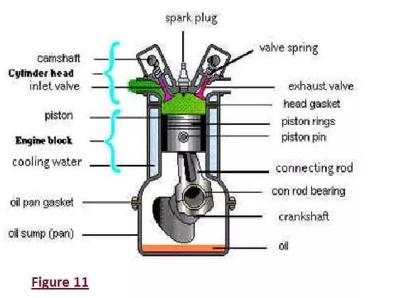
The lubricating system of a four-stroke engine typically uses a wet sump lubrication system, where oil is stored in a sump located at the bottom of the engine. A lube oil pump, powered by the engine itself, circulates the lubricating oil through the engine’s various components in a closed loop.

lubrication in 4 four stroke engine

Key Components and Process Flow:

1.Lube Oil Sump: The oil is stored in the sump located at the bottom of the engine. The sump holds the oil and acts as the source from which the lubricating oil pump draws oil.

2.Lube Oil Pump: The lube oil pump is driven by the engine and is responsible for circulating oil throughout the system. It pumps oil from the sump and directs it through the rest of the system.

3. Primary Filter: After being drawn from the sump, the oil first passes through a primary filter, which removes larger particles and impurities from the oil, ensuring cleaner oil flows through the system.

4. Oil Cooler: After filtration, the oil passes through an oil cooler, which reduces the temperature of the oil, ensuring that it can efficiently lubricate engine components while preventing overheating.

5. Main Filter: The oil then passes through the main filter for final filtration, removing any remaining impurities.

6. Oil Distribution: After passing through the cooler and main filter, the oil splits into two separate lines:

  1. Lubricating Main Bearings and Crankshaft:
    • One line directs oil to the main bearings. From there, oil passes through holes in the crankshaft, reaching the crankpin for lubrication.
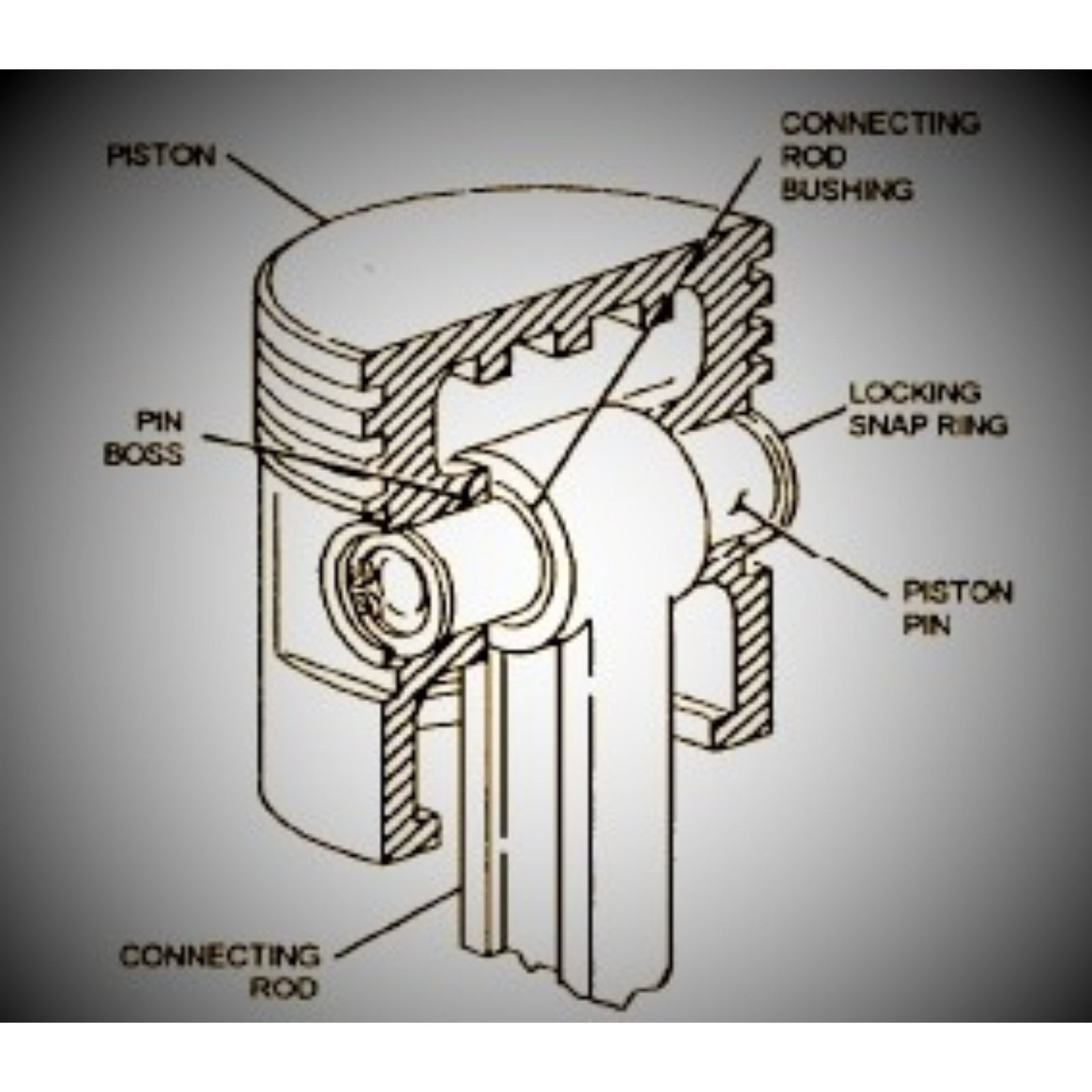
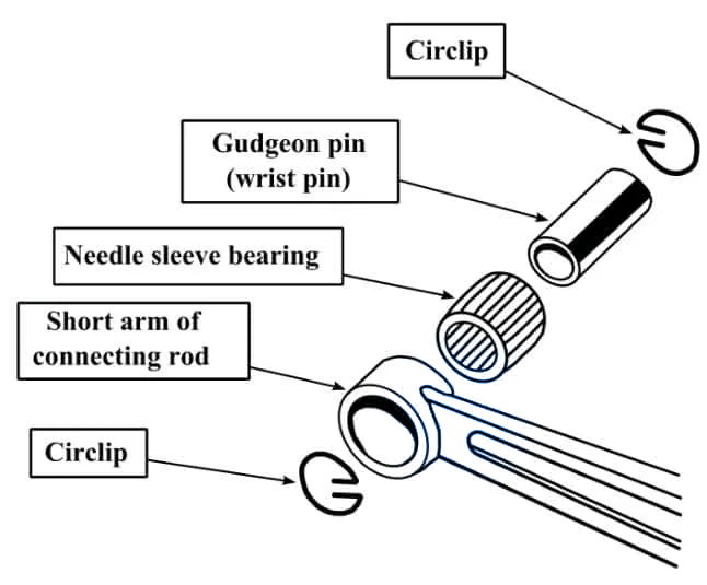
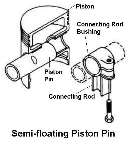
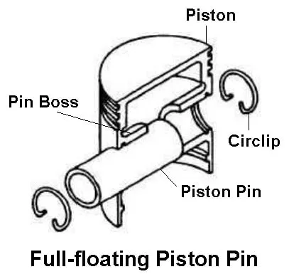
    • The oil continues inside the crankshaft, moving toward the piston pin (gudgeon pin) for lubrication. The lubricated piston pin ensures the smooth movement of the piston inside the cylinder.
  2. Lubricating Cylinder Liners:
    • Through the end of the gudgeon pin, oil also lubricates the cylinder liners, ensuring minimal friction between the piston and the cylinder walls.
    • Scraper rings on the piston remove excess oil from the cylinder liner, directing it back to the sump.

7. Lubricating Gear System: The second line from the main filter goes to lubricate the engine’s gear system, which includes various pumps and components attached to the crankshaft.

  • Components like the lube oil pump, jacket water pump, governor, rocker arm pump, and fuel oil pump are all lubricated from this line to ensure smooth operation.

Key Lubricated Components:

  • Main Bearings: Support the crankshaft, allowing it to rotate smoothly.
  • Crankshaft and Crankpin: Transmit the engine’s power; lubrication is critical to reduce wear due to friction.
  • Piston Pin (Gudgeon Pin): Connects the piston to the connecting rod, needing lubrication for smooth piston movement.
  • Cylinder Liners: The inner walls of the cylinder where the piston moves up and down; lubricated to reduce friction and wear.

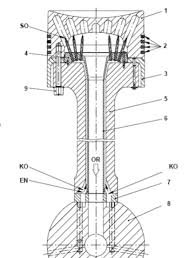
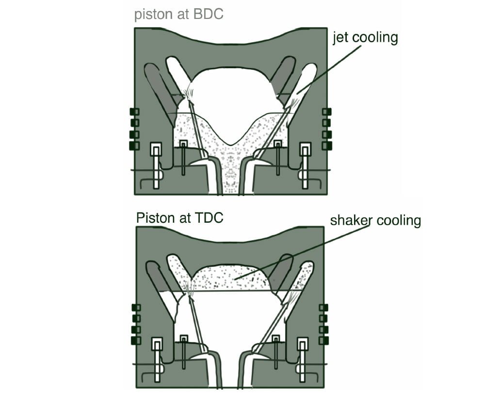
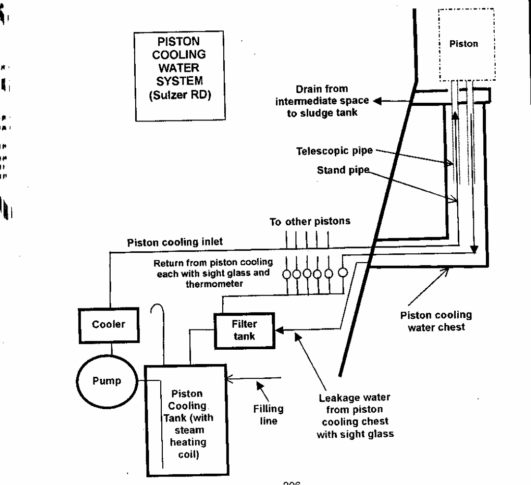
Piston Cooling (To be Discussed Later):

  • In addition to lubricating the engine components, the lube oil system also plays a role in piston cooling, where oil circulates through or around the piston to regulate its temperature. You plan to explain this further in a future section.

Line Diagram of 4-stroke engine lubricating system

Lubricating oil from the oil sump tank >>> Primer filter >>> The lubricating oil pump >>> lubricating oil cooler >>> lubricating oil pressure relief valve >>> lubricating oil filter >>> lubricating oil main pipe.

Now lubricating oil main pipe branched into two lines :-

1. The one line lubricates the main bearing shell, crank pin bearing shell and piston pin bush.

2. While the other line lubricates the cam shaft bearing shell, tappet surroundings, governor and idle gear bush.

Then they will come together to drop into the sole plate. In some modes of engines, the valve rocker arm is lubricated in this circulation.

Pressure Type Lubrication System

This system ensures that all critical engine parts receive continuous lubrication, minimising wear and tear, reducing friction, and preventing overheating of components.

Here, a provided an in-depth explanation of the pressure-type lubrication system in a four-stroke engine, focusing on the key parts that require lubrication to ensure smooth engine operation. Here’s a clearer breakdown of the components and their lubrication process: …

The above see that lubrication system is pressure type lubrication system. Now we see all the parts which is used for lubrication. The main parts which is lubricated are :-

  • Main Bearings
  • Crank Pin or Bottom end bearings
  • Top end bearings or Gudgeon pin Or piston pin
  • Cylinder liner lubrication
  • Camshaft
  • Crankshaft drive
  • Governor drive
  • Turbocharger
  • Rocker arm system

Components and Lubrication Details:

  1. Main Bearings:
    • The main bearings support the crankshaft and are connected to the connecting rod. Due to the heavy loads they bear, proper lubrication is critical to reduce wear and ensure smooth motion.
    • Lubrication Process: Lube oil, under pressure from the lube oil pump, passes through holes in the bearings to provide continuous lubrication.
  2. Crank Pin Bearings (Bottom End Bearings):
    • These bearings connect the crankshaft to the crank pin, allowing the conversion of reciprocating motion (up and down movement of the piston) into rotary motion.
    • Lubrication Process: The oil is transferred from the main bearing through an internal passage in the crankshaft, which delivers the oil to the crank pin bearings.
  3. Gudgeon Pin (Piston Pin) or Top End Bearings:
    • The gudgeon pin connects the piston to the connecting rod, experiencing reciprocating motion. Proper lubrication is critical to prevent friction between the piston and the connecting rod.
    • Lubrication Process: Oil is delivered to the gudgeon pin through passages inside the crankshaft, continuing the flow from the crank pin.
  4. Cylinder Liner Lubrication:
    • The cylinder liner forms the sliding surface for the piston. Lubrication here is necessary to reduce friction between the piston and the liner.
    • Lubrication Process: Oil from the gudgeon pin passes through the end of the piston pin and reaches the cylinder walls. Scraper rings on the piston distribute the oil over the liner, while excess oil is scraped back into the sump.
  5. Camshaft:
    • The camshaft drives the operation of various pumps and other engine components by controlling the timing of the valve operation (inlet and exhaust valves).
    • Lubrication Process: A nozzle is provided on top of the camshaft, where oil is sprayed to lubricate the gears involved in the camshaft’s operation.
  6. Crankshaft Drive:
    • The crankshaft drive also requires lubrication, particularly in the areas where gears are involved in transmitting power to other components.
    • Lubrication Process: A nozzle sprays oil onto the gear meshes to ensure proper lubrication and reduce friction.
  7. Governor Drive:
    • The governor controls the engine’s speed by regulating fuel delivery based on load conditions.
    • Lubrication Process: The governor mechanism is lubricated via oil delivered through a dedicated piping system to the gear mesh, ensuring smooth operation.
  8. Turbocharger:
    • Some engines use the same lube oil system to lubricate the bearings of the turbocharger. The turbocharger has two main bearings: the turbine-side bearing and the blower-side bearing.
    • Lubrication Process: A branch of the lube oil system is used to deliver oil to both bearings, ensuring proper lubrication for the high-speed rotating shaft of the turbocharger.
    • Alternative Lubrication: In some engines, splash lubrication is used for the turbocharger bearings. The bearings dip into the oil in the sump, allowing them to be lubricated as they rotate.
  9. Rocker Arm System:
    • The rocker arm controls the opening and closing of the inlet and outlet valves, and its lubrication is essential for smooth valve operation.
    • Lubrication Process: In some engines, the rocker arm system is lubricated by the same lube oil pump. After passing through the filters, one oil line branches off to lubricate the rocker arm.

Special Pump: In Daihatsu diesel engines, a special rocker arm pump (internal gear pump) is provided exclusively for lubricating the rocker arm system, offering precise control of lubrication in this area.

Line diagram of rocker arm system

Lubrication of rocker arm system are explained below :-

The Rocker arm lube oil tank >>> torchoid pump ( with safety valve ) >>> lube oil filter >>> Supply oil main pipe >>> rocker arm shaft bush >>> rocker arm end >>> returning main pipe >>> rocker arm lube oil tank

Rocker Arm Lube Oil Tank:

This tank stores the lubricating oil specifically for the rocker arm system. It is separate from the engine’s main lubrication system to ensure that the oil remains clean and free from contamination.

Torchoid Pump (with Safety Valve):

The torchoid pump is responsible for pressurizing and pumping the lubricating oil from the tank. The safety valve ensures that oil does not exceed safe pressure levels, protecting the system from damage.

Lube Oil Filter:

After the oil is pumped, it passes through a lube oil filter, which removes contaminants and impurities. This step is crucial for maintaining the quality of the oil used for lubrication.

Supply Oil Main Pipe:

The filtered oil travels through the supply oil main pipe to reach various lubrication points in the rocker arm system.

Rocker Arm Shaft Bush:

The oil first reaches the rocker arm shaft bush, providing lubrication to the bushings that support the rocker arm’s pivot point.

Rocker Arm End:

The oil then flows to the rocker arm end, where it lubricates the contact points responsible for actuating the engine’s valves.

Returning Main Pipe:

After lubricating the rocker arm, the oil returns through the returning main pipe to be recirculated back into the rocker arm lube oil tank.

Rocker Arm Lube Oil Tank (Return):

Some oil returns directly to the rocker arm lube oil tank from the oil pressure relief valve located at the end of the supply oil main pipe. This valve allows excess oil to be returned to the tank, preventing overpressure in the system.

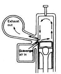
Line Diagram of 2-stroke engine lubricating system

Lubricating oil from the oil sump tank >>> Primer filter >>> The lubricating oil pump >>> lubricating oil cooler >>> lubricating oil pressure relief valve >>> lubricating oil filter >>> lubricating oil main pipe.

Now lubricating oil main pipe branched into two lines :-

1. The one line lubricates the main bearing shell, crank pin bearing shell and piston pin bush.

2. While the other line lubricates the cam shaft bearing shell, tappet surroundings, governor and idle gear bush.

Then they will come together to drop into the sole plate. In some modes of engines, the valve rocker arm is lubricated in this circulation.

Lubricating Oil pump :- lubricating oil pump used here is external gear pump. It is located at the front of the engine and is powered by the crankshaft via a coupling or a gear wheel.

Note :- In some engine splash lubrication system is used. In this lubrication system, lube oil is submerged partially. when crankshaft rotates, it splash the lube oil on surfaces.

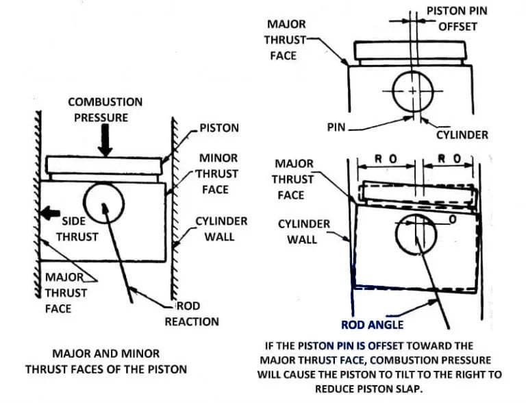
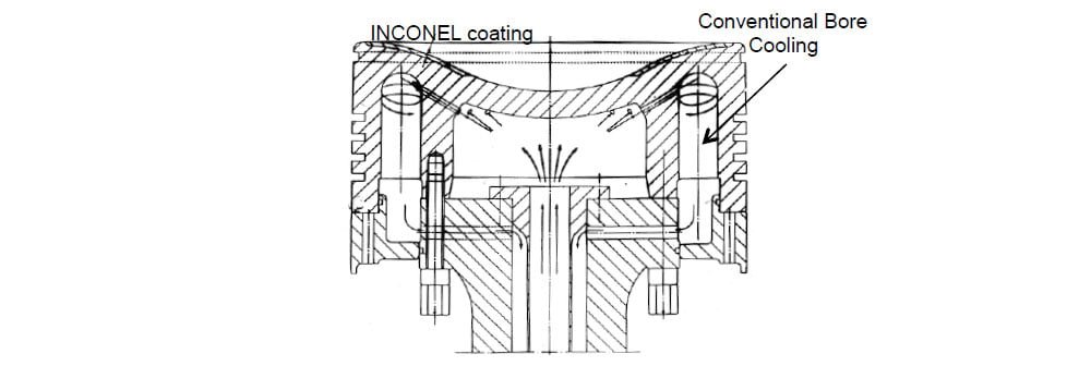
How piston cooling is done in 4 stroke engine ?

As piston get hot too much because it is directly in contact with combustion. So, we need to to cool it working properly. Otherwise failure of Piston. Piston cooling is done by the Nozzle provided near the under space of piston.

This is all about lubrication of 4 stroke engine or auxiliary engine.

FAQ ( Frequently Asked Questions )

Which type of lubrication system is used in stroke engine?

 type of lubrication system used as a dry-sump type, wet-sump type, force-feed type, or splash type.

Check Out Other Important Topics

IC EngineImportant PDFsBoilersSynergy Maritime ExamNaval ArchMEO Class 4
Interview QuestionsDifference BetweenTypes of PumpsAuxiliary MachinesTypes of ValvesHome

Bed Plate – Functions And Structure of IC engine

What is a Bedplate of Diesel Engine ?

The bed plate forms the foundation of the engine (or constructions )on which the other structural component such as A-frame, all column, and Guides are mounted and it can withstand heavy fluctuating stresses from working parts.

Bedplate supports the Load of the Engine and it’s other Constructional parts and provide a base for the large mass.

Bed Plate

What are the Functions of a Bed Plate ?

The functions of a bed plate, particularly in the context of marine or industrial engines, are critical for ensuring proper operation, stability, and efficiency. Here’s a consolidated overview based on your points:

  1. Load Transmission: The bed plate transmits the engine’s load, including the propeller thrust, to the ship’s structure. It distributes this load over an adequate area, ensuring that the crankshaft remains aligned for optimal performance.
  2. Oil Management: It collects crankcase lubrication oil and facilitates its return to the drain tank for recirculation, maintaining proper lubrication and cooling of engine components.
  3. Structural Integrity: The bed plate is bolted to the tank top, which is reinforced with thicker plates and girders to provide additional strength and stability, ensuring it can support significant forces during engine operation.
  4. Support Base: Acting as a foundational element, the bed plate provides essential support to the entire engine structure, contributing to the overall stability of the system.
  5. Static Weight Support: It bears the static weight of the entire engine and its components, ensuring that forces are effectively transferred to the ship or structure.
  6. Dynamic Load Support: The bed plate also supports the dynamic loads generated by the engine’s running gear, absorbing vibrations and shocks that occur during operation.
  7. Crankshaft Alignment: The crankshaft fits into the bed plate via main journal bearings, ensuring the crankshaft is held in perfect alignment for efficient functioning and reduced wear.

These functions collectively ensure that the engine operates smoothly, safely, and efficiently, which is crucial for the overall performance of marine vessels or industrial machinery.

What are the fundamental requirements of Bed plate ?

The fundamental requirements of a bed plate in an engine are essential to ensure its structural integrity, functionality, and efficiency. Here’s a breakdown of each requirement:

  1. Strength
    The bed plate must have sufficient strength to bear the static and dynamic loads of the engine, including the weight of the engine components and the forces generated during operation.
  2. Lightness
    While maintaining strength, the bed plate should be designed to be as light as possible to avoid adding unnecessary weight to the overall engine structure, especially in marine and automotive applications where weight efficiency is crucial.
  3. Toughness
    Toughness is necessary to withstand impact and fatigue stresses. The bed plate must endure repeated cycles of mechanical loads without cracking or deforming, ensuring long-term durability.
  4. Simple Design
    A simple design facilitates ease of manufacturing, assembly, and maintenance. Simplicity also ensures that the bed plate remains reliable while minimizing potential points of failure.
  5. Seal
    The bed plate must be able to seal off the crankcase to prevent oil leaks and ensure that the lubrication system operates effectively, keeping contaminants out of the engine.
  6. Access
    Access points should be provided in the bed plate for inspection, maintenance, and repairs of internal components like the crankshaft and bearings, ensuring efficient engine servicing.
  7. Dimensions
    The dimensions of the bed plate must be precise, fitting the engine structure perfectly to ensure proper alignment of components like the crankshaft, and ensuring compatibility with the overall design of the engine and surrounding structure.
  8. Rigidity
    The bed plate must maintain rigidity to prevent deformation under load, ensuring that the engine structure remains aligned and that mechanical stresses are distributed evenly.

These requirements ensure that the bed plate can provide the necessary support, alignment, and durability for efficient engine operation.

Read About : Difference between two Cross head and Trunk type piston engine

Construction

Sure! Here’s a simpler breakdown of the construction of bed plates:

1. Small Engine Bed Plates

  • Material: Small engines generally have bed plates made from one solid piece of cast iron.
  • Design: This design is a single casting, meaning it’s all one part, making it strong and stable.
  • Vibration Dampening: Cast iron helps absorb vibrations, making the engine run more smoothly.

2. Large Engine Bed Plates

  • Material and Structure: Large engines use fabricated mild steel for their bed plates.
  • Configuration: These have:
  • Longitudinal girders: These are long beams that run the length of the bed plate.
  • Cast steel transverse girders: These are shorter beams that support the crankshaft bearings, helping share the load evenly.

3. Material Requirements

  • Carbon Content: For large marine diesel engines, the materials used should have low carbon content (up to 0.23%). This helps the metal stay strong and easy to work with during construction.

4. Key Points in Bed Plate Construction

  • Strength and Rigidity: Bed plates must be strong enough to hold the engine without bending or breaking.
  • Vibration Control: Small bed plates use cast iron to help manage vibrations; larger bed plates may need special designs to do this.
  • Easy Maintenance: The bed plate should be designed so that engine parts can be easily reached for checking and repairs.

In short, the construction of bed plates is important for keeping engines stable and running smoothly, with different designs for small and large engines.

What are the forces act on bed plate

The forces are :-

  • Firing pressure (Cylinder gas pressure )
  • Forces of inertia of moving masses
  • Side thrust due to movement of connecting rod.
  • Whole weight of engine act on the bed plate.
  • Torque due to rotation of propeller.
  • Hull deflection.
  • Vibrations forces (It is generated due to fluctuations in torque,shock loading and thermal stress )
  • Rough weather (Forces due to ship’s movement in heavy seas).

Materials use

◆ Cast iron

Hybrid: fabricated mild steel for longitudinal Cast steel for transverse.

Maintenance / What are the checks to be carried on the bed plate during inspections

Since Bedplate is the base of the Engine it should be in proper order for the proper functioning of the Engine. And for that it should be regularly checked and maintenance should be carried out.

Maintaining the bed plate is crucial for the proper functioning of the engine. Regular inspections are essential to ensure its integrity and performance. Below are key checks to perform during inspections:

1. Cracks

  • Common Issue: Cracks often develop over time due to prolonged use and heavy loading.
  • Areas to Inspect:
  • Welded Joints: Examine the areas where transverse girders connect to longitudinal girders.
  • Bearing Pockets: Check under the bearing pockets for radial cracks or cracks along the pocket line.
  • Tie Bolt and Bolt Holes: Look for radial cracks at tie bolts and around the holes for frame bolts.
  • Lightening Holes: Inspect around the lightening holes in the bed plates and girders.
  • Main Bearing Keeps: Inspect the base of the main bearing keeps for any signs of cracking.

2. Welding

  • Inspection: Check the condition of welding joints, especially if recent welding has been done, ensuring there are no defects.

3. Faulty Casting

  • New Deliveries: Newly delivered engines with cast components should be tested for defects in casting.

4. Corrosion

  • Vulnerability: Since the bed plate is located at the lowest part of the engine, it is prone to corrosion. Inspect it for any signs of rust or degradation.

5. Loose Frame

  • Impact of Loading: Loose frames can occur due to excessive loading or issues with tie rods.
  • Check Tie Rods: Ensure that tie rods connecting the bed plate to the A-frame and engine entablature are tight and that no part of the bed plate is loose.

6. Faulty Holding Down Bolts

  • Inspection for Tightness: The holding down bolts secure the bed plate to the ship’s bottom structure. Regularly check these bolts to ensure they are secure.

7. Oil Leaks

  • Lubrication System: The bed plate is involved in storing and transferring lube oil. Inspect the bed plate and joints for any oil leaks, which can indicate issues with seals or connections.

Regular checks on cracks, welding, casting quality, corrosion, frame integrity, bolt tightness, and oil leaks are critical for maintaining the bed plate’s health and ensuring optimal engine performance.

What are the cause of breaking of bed plate ?

The breaking of a bed plate can occur due to several factors, including:

  1. Overloading: Excessive weight or force beyond the bed plate’s designed capacity can lead to fractures or failures.
  2. Uneven Loading: If engine loads are not evenly distributed, it can create stress concentrations that weaken the bed plate and cause breaking.
  3. Faulty Maneuvering Techniques: Incorrect handling or operation of the engine, such as abrupt changes in speed or direction, can apply undue stress on the bed plate.
  4. Loosened Tie Bolts: If the bolts securing the bed plate become loose, it can lead to misalignment and increased stress in certain areas, making the bed plate susceptible to breaking.

Addressing these issues through proper design, maintenance, and operation can help prevent bed plate failures.

Faults in Bedplate

Faults in a bed plate can lead to operational issues and may affect the performance of the engine. Here are some common faults:

1.Cracks: Cracks can develop due to overloading, fatigue, or manufacturing defects, compromising the structural integrity of the bed plate.

2.Oil Leaks: Oil leaks can occur from damaged seals or joints, leading to lubrication issues and potential engine damage. This can often be caused by wear or improper installation.

3.Loose Chocks: Chocks are used to secure the bed plate in position. If they become loose, they can lead to misalignment of the engine components, causing vibrations and further mechanical issues.

    Regular inspections and maintenance can help identify and address these faults before they lead to serious problems.

    Source : https://www.wartsila.com/encyclopedia/term/bedplate

    Also Read : Fresh Water Generator On ships

    Read more : Boiler Mountings

    Check Out Other Important Topics

    IC EngineImportant PDFsBoilersSynergy Maritime ExamNaval ArchMEO Class 4
    Interview QuestionsDifference BetweenTypes of PumpsAuxiliary MachinesTypes of ValvesHome

    Difference Between Crosshead And Trunk Type Piston engine

    Difference between Crosshead and Trunk type Piston engine

    Difference between crosshead and trunk type Piston engine are as follows :-

    Difference between Crosshead and Trunk type Piston engine

    Crosshead Type Engine

    It looks like you’d like the crosshead type engine section expanded with the details you provided. Here’s a refined version in a formal tone that aligns with the earlier structure of the blog post:


    Crosshead Type Engine: Design and Features

    1. Connecting Rod and Piston Rod
      A defining feature of the crosshead type engine is the presence of both a connecting rod and a piston rod. The piston rod connects the piston to the crosshead assembly, which in turn is connected to the connecting rod. This distinction separates crosshead engines from trunk type engines, which lack a piston rod.
    2. Diaphragm Separation
      Crosshead engines are equipped with a diaphragm that separates the cylinder space from the crankcase. This feature prevents the mixing of lubricants, allowing for different lubrication systems to be used in the cylinder and the crankcase, thus enhancing overall engine performance and longevity.
    3. Bearing Assembly at the Upper Part
      In the upper part of the crosshead engine, the connecting rod is linked to the crosshead assembly. This assembly, which consists of a crosshead block, pins, and slippers, plays a critical role in ensuring smooth movement and transferring forces efficiently. The crosshead assembly connects to the lower part of the piston rod, which is rigidly fixed to the piston, creating a solid structure that minimizes stress and wear.
    4. Separate Cylinder Lubrication
      One of the key features of the crosshead engine is its separate lubrication system for the cylinder and the crankcase. The cylinder uses a distinct oil from the crankcase, tailored specifically for the high-temperature environment of the cylinder. This system enhances the engine’s efficiency and prolongs its lifespan.
    5. Transverse Force Management
      The transverse forces generated by the oscillation of the connecting rod are managed by the crosshead and its guides. These forces are transmitted through the crosshead guides to the engine structure, reducing wear on the piston and piston rod assembly.
    6. Crosshead Assembly as a Connecting Mechanism
      The crosshead assembly is a critical connecting mechanism between the piston rod and the connecting rod. The piston is rigidly fixed to the piston rod, and this rigid connection ensures that forces are efficiently transmitted from the piston to the connecting rod via the crosshead assembly.
    7. Higher Torque at Low Speeds
      Crosshead engines are capable of generating higher torque at lower speeds, making them ideal for applications requiring heavy-duty, low-speed performance. This is a key advantage in marine propulsion systems and other industrial applications where low-speed operation is crucial.
    8. Increased Height Requirements
      Due to the complexity of the crosshead assembly and the inclusion of both a piston rod and a connecting rod, crosshead engines require more vertical space. For the same power and speed, a crosshead engine will have a taller profile than a trunk type engine.
    9. Transverse Thrust Transmission
      The transverse thrust generated within the engine is effectively transmitted to the engine structure through the crosshead guides, which absorb and manage these forces. This ensures that the engine operates smoothly without excessive stress on the moving parts.
    10. Higher Manufacturing Costs
      The complexity of the crosshead assembly and the need for separate lubrication systems contribute to higher manufacturing costs. The additional components and engineering precision required make these engines more expensive to produce, though they offer superior durability and performance under demanding conditions.
    11. More Height for Same Power and Speed
      As mentioned earlier, due to their complex structure, crosshead engines require greater height for the same power and speed when compared to trunk type engines. This can be a limitation in applications where space is a critical factor.
    12. Efficient Use of Low-Grade Fuel
      Crosshead engines are designed to handle low-grade fuels efficiently, as their operation at lower speeds allows more time for complete combustion. This ability makes them ideal for applications where fuel cost savings are a priority.

    Trunk type engine

    It looks like you’re reiterating the details of the trunk type engine. Here’s a refined version in formal tone that incorporates your points:


    Trunk Type Engine: Design and Features

    1. Absence of a Piston Rod
      In a trunk type engine, only the connecting rod is present, directly connecting the piston to the crankshaft. There is no piston rod, which simplifies the engine design. This contrasts with crosshead engines, which have both a connecting rod and a piston rod.
    2. No Diaphragm
      Unlike crosshead engines, the trunk type engine has no diaphragm separating the cylinder from the crankcase. As a result, there is no physical barrier between the two, which allows for a unified lubrication system.
    3. Direct Connection to Piston via Gudgeon Bearing Assembly
      The upper part of the connecting rod in a trunk type engine is connected directly to the piston through a gudgeon bearing assembly. This eliminates the need for additional components like a crosshead, simplifying the engine structure.
    4. Unified Lubrication System
      In trunk type engines, the same lubrication oil is used for both the cylinder and the crankcase. While this simplifies maintenance, it can potentially result in increased wear due to the mixed operating conditions.
    5. Piston Skirt Absorbs Transverse Thrust
      The piston skirt in trunk type engines absorbs the transverse thrust caused by the oscillation of the connecting rod. This function, performed by the crosshead assembly in crosshead engines, is managed by the piston skirt in trunk engines.
    6. No Crosshead Assembly
      In trunk type engines, the connecting rod is attached to the piston via a gudgeon pin, and there is no crosshead assembly. This significantly reduces the complexity of the engine compared to the crosshead type.
    7. High Power at Medium or High Speeds
      Trunk type engines are designed to operate efficiently at medium to high speeds, where they produce high power output. This makes them suitable for applications where speed is a critical factor.
    8. Compact Design and Reduced Headroom
      One of the advantages of trunk type engines is their compact design. They require less headroom compared to crosshead engines because there is no piston rod or crosshead assembly. This makes them ideal for installations where space is limited.
    9. Piston Skirt Handles Side Thrust
      The side thrust created by the movement of the crankshaft and connecting rod is absorbed by the piston skirt in trunk type engines. This design concentrates the mechanical stress on the piston, requiring the skirt to be strong enough to withstand these forces.
    10. Lower Manufacturing Costs
      Trunk type engines have lower manufacturing costs due to their simpler design and fewer components. The absence of a crosshead assembly and diaphragm reduces the complexity of the engine, making it more cost-effective to produce.
    11. Less Height for Same Power and Speed
      Due to the simplified design, trunk type engines require less vertical space for the same power output and speed compared to crosshead engines. This reduction in height is a significant advantage in applications where space constraints are a factor.
    12. Efficient Use of Low-Grade Fuel
      Trunk type engines can efficiently use low-grade fuels, making them cost-effective in operations where fuel quality is variable. The engine’s ability to run efficiently on such fuels provides flexibility in fuel choices depending on operational requirements.

    Here a Very Easy table comparing crosshead type engines and trunk type engines based on the information you’ve provided:

    FeatureCrosshead Type EngineTrunk Type Engine
    Piston RodHas both a connecting rod and a piston rod.Only the connecting rod; no piston rod.
    DiaphragmHas a diaphragm separating the cylinder from the crankcase.No diaphragm.
    Upper Part ConnectionConnecting rod is connected to the piston rod via a crosshead assembly.Connecting rod is directly connected to the piston via a gudgeon bearing assembly.
    Lubrication SystemSeparate oils for cylinder and crankcase.Same lube oil used for both the cylinder and crankcase.
    Transverse Thrust AbsorptionTransverse thrust is absorbed by the crosshead and its guide.Transverse thrust is absorbed by the piston skirt.
    Crosshead AssemblyHas a crosshead assembly connecting the piston rod to the connecting rod.No crosshead assembly; uses a gudgeon pin to connect the connecting rod to piston.
    PerformanceDevelops high torque at low speeds.Produces high power at medium or higher speeds.
    Space RequirementsRequires more height due to complex structure.Requires less headroom; more compact design.
    Transverse Thrust HandlingThrust is transmitted to engine structure through crosshead guides.The piston skirt handles the side thrust.
    Manufacturing CostsHigher due to complexity and additional components.Lower due to simpler construction.
    Height for Same Power and SpeedMore height needed for the same power and speed.Requires less height for the same power and speed.
    Fuel EfficiencyCan efficiently use low-grade fuel over time due to longer combustion.Can also use low-grade fuel efficiently, suitable for various applications.

    This table provides a clear and easy comparison between the two engine types. Let me know if you’d like to adjust or add more details!

    Follow us on Twitter

    People also ask

    What is trunk type engine ?

    A type of an internal combustion engine in which the connecting rod is directly connected to the piston by Gudgeon pin (also called piston pin ).

    Advantage of crosshead type engine ?

    Advantage are :-

    1. The Cross head type engine are able to devlop higher power at lower rotational speed of the engine than trunk type engines.It is because the space available for the crosshead bearing is greater than the space within the piston for gudgeon bearing assembly.
    2. The combustion product contamination of crankcase lube oil is less than the trunk type engine.
    3. Total costs of lubricants of crosshead engine is less than the trunk type engine having same power.

    What is a cross head engine ?

    Why do pistons have skirt ?

    Skrt do two functions

    1.The piston skirt consists of spaces for gudgeon pin which transmits power to the con. rod

    2.The skirt also help in transmitting the side thrust produced by the connecting rod.

    What is the name the portion below the piston boss?

    Ans :- Skirt
    ring belt: is the upper-middle part of the piston when the piston rings are located.

    pin

    boss: is the lower-middle part of the piston which contains the piston pin.


    What are the 3 types of piston rings?


    Why crosshead lubrication is difficult?


    What is the largest diesel engine in the world?


    What is a cross head type diesel engine?


    What is a crosshead bearing?
    a sliding member of a reciprocating engine for keeping the motion of the joint between a piston rod and a connecting rod in a straight line.

    Can you use a piston with a broken skirt?


    Nope, no good, never, shouldn’t even think about it, NOT IN ANY ENGINE. That’s just asking for more damage or destruction.

    Can you reuse old Pistons?


    Understanding the Various Parts of a Ship: A Detailed Guide

    Ships, whether for transporting goods or people, are intricate machines requiring a sophisticated combination of design, engineering, and construction. Understanding the various parts of a ship is crucial to ensuring smooth navigation and safe transport.

    The anatomy of a ship consists of multiple parts, each with its distinct purpose and function. These parts include the hull, superstructure, propulsion system, navigation and communication equipment, cargo handling equipment, safety equipment, electrical systems, and plumbing and sanitation systems. Knowing how each of these components works is essential in comprehending the ship’s anatomy, construction, and systems.

    From the bow to the stern, ships’ parts come in various shapes, sizes, and materials. The design and construction of the vessel must consider its purpose, route, and intended use. Every component plays a vital role in the ship’s overall functionality, stability, and efficiency.

    As we explore these ship parts and systems in detail, you will gain a better understanding of how they work together to ensure smooth maritime navigation and efficient transport of goods and people. So, let’s dive into the fascinating world of ship anatomy and construction!

    Parts of Ship

    Ship Hull

    The ship hull is the main body of the vessel that provides buoyancy and stability. It is the outermost layer and is responsible for withstanding the forces of the sea. The hull is made up of several components that work together to form a rigid and durable structure.

    Hull Structure

    The hull structure is made up of the bottom, sides, and deck of the ship. The bottom of the hull is called the keel, which runs the length of the ship and provides support and stability. The sides of the hull are called the plating or shell and are made of steel or aluminum to withstand the harsh marine environment. The deck is the top of the ship and provides a surface for crew and cargo.

    Hull Components

    The bow of the ship is the front and is designed to cut through the water efficiently. The stern is the back of the ship and provides propulsion and steering. The rudder, which is attached to the stern, provides directional control. The propeller is also attached to the stern and provides the force needed for movement. The hull also contains various openings such as hatches, vents, and portholes for access and ventilation.

    Ship Superstructure: The Brain and Housing of the Vessel

    A ship’s superstructure is the upper part of the ship above the main deck, which includes the bridgedeckhouse, and accommodations for the crew and passengers. It serves as the brain and housing of the vessel, containing essential systems and equipment necessary for safe and efficient navigation.

    The Bridge

    The bridge is the command center of the ship and is located at the front of the superstructure. It provides a panoramic view of the ship’s surroundings and serves as the primary control station for navigation, communication, and maneuvering. The bridge is equipped with essential instruments such as radarGPS, and compasses, which provide real-time data on the ship’s position, speed, and direction.

    The Deckhouse

    The deckhouse is the main living quarters for the crew and is located behind the bridge. It provides sleeping quarters, a galley, mess hall, and other amenities necessary for the crew’s comfort and well-being during long voyages. The deckhouse may also house other equipment and systems, such as the ship’s fire control center and emergency equipment storage.

    Accommodations

    The accommodations area is located towards the rear of the superstructure and includes cabins or living quarters for the crew and passengers. These quarters can range from shared rooms to private suites with en-suite bathrooms. The area also includes common areas such as lounges, recreational areas, and medical facilities.

    The ship’s superstructure is critical in providing a safe and comfortable environment for the crew and passengers during long voyages. It is also responsible for housing and protecting the essential systems and equipment necessary for navigation, communication, and other ship operations.

    Propulsion System

    One of the most essential systems onboard a ship is the propulsion system, which provides the necessary power to move the vessel through the water. The propulsion system consists of various components, including the engine roompropellers, and engines.

    Engine Room

    The engine room is typically located in the lower part of the ship and houses the ship’s engines, generators, and other machinery. It is a critical area that requires constant monitoring and maintenance to ensure the ship’s smooth operation. The engine room is also where the crew can perform repairs and maintenance on the ship’s machinery.

    Propellers

    Propellers are essential components of a ship’s propulsion system, generating the force that moves the vessel forward or backward. The number and size of the propellers vary depending on the ship’s size and design, and they are typically located at the stern of the ship.

    Engines

    The type of engine used in a ship depends on the ship’s size, speed, and power requirements. Common types of engines include diesel engines, steam turbines, and gas turbines. They are typically located in the engine room and are responsible for generating the power to turn the propellers and move the ship through the water.

    Parts of a ship Diagram

    Navigation and Communication Equipment

    Navigation and communication equipment are critical systems on any ship, ensuring safe navigation and effective communication with other vessels and shore.

    One of the most important pieces of navigation equipment on a ship is radar, which uses radio waves to detect nearby objects. The radar system consists of a transmitter, receiver, and display screen, and it is used to detect and track other vessels and obstacles on the water.

    GPS (Global Positioning System) is another essential tool for navigation. It uses satellites to determine a ship’s exact location and provides information such as speed, direction, and distance to other locations.

    Communication equipment on a ship includes radios, which allow for communication with other vessels and shore stations. In addition, a ship’s communication system may include satellite phones, email, and other forms of electronic communication.

    Most ships also have a bridge navigation system, which integrates radar, GPS, and other navigation tools into a centralized display. This allows for easier navigation and better situational awareness for the ship’s crew.

    Risk Management

    Effective navigation and communication are critical components of risk management on a ship. By using radar, GPS, and other tools, a ship’s crew can avoid collisions with other vessels and hazards such as reefs and rocks. In addition, effective communication can be the key to obtaining assistance during an emergency.

    For these reasons, navigation and communication equipment are among the most important systems on any vessel, and they require careful maintenance and attention to ensure their proper functioning.

    Cargo Handling Equipment

    The cargo handling equipment on a ship is an essential component of its operations. It allows for the efficient loading, unloading, and securing of cargo, ensuring the timely delivery of goods. The main components of a cargo handling system include cranes and cargo holds.

    Cranes

    Cranes are used to hoist cargo on and off the ship. They are typically mounted on the ship’s deck and come in various sizes and types. Some cranes are designed to lift heavy loads, while others are more suitable for lighter cargo. Cranes can also be operated manually or electronically, depending on the ship’s specifications.

    Modern cargo handling cranes use hydraulic or electric power for their operation. Hydraulic cranes rely on fluid pressure to lift and move heavy loads, making them ideal for handling heavy cargo. Electric cranes use electric motors for movement and are best suited for lighter loads.

    Cargo Holds

    The cargo hold is the area where the cargo is stored during transportation. It is typically located below the main deck and can be accessed through large doors on the ship’s hull. Cargo holds must be designed to accommodate various types of cargo while ensuring the safety of crew members and the ship.

    The cargo hold must also be equipped with various systems to ensure the safety of the cargo during transportation. This includes systems for securing the cargo, monitoring its temperature and humidity, and preventing damage during rough seas.

    In summary, the cargo handling equipment on a ship is vital to its operations. The cranes and cargo holds work together to ensure the timely delivery of cargo while maintaining the safety of the crew and the ship.

    Safety Equipment

    While ships are designed with safety in mind, accidents can still happen at sea. That’s why it’s crucial for ships to have appropriate safety equipment on board. Let’s take a look at some of the most important safety equipment found on ships:

    Lifeboats and Life Rafts

    Lifeboats and life rafts are essential pieces of safety equipment that are designed to keep passengers and crew members safe in the event of an emergency. Lifeboats can be launched from the deck of the ship and are typically equipped with oars and a motor to help them maneuver in the water. Life rafts are inflatable rafts that can be stored on deck and deployed when needed.

    Fire Suppression Systems

    Fires can be extremely dangerous on board a ship. That’s why many ships are equipped with fire suppression systems that can help to quickly extinguish any flames that might break out. These systems typically use water, foam, or gases to put out fires.

    Emergency Position Indicating Radio Beacons (EPIRBs)

    If a ship goes down or becomes stranded at sea, it’s essential for rescuers to be able to locate the ship and its passengers quickly. EPIRBs are small devices that can be activated in an emergency, sending out a distress signal that can be picked up by rescue teams. These devices are typically waterproof and can be attached to life jackets or other safety equipment.

    Personal Flotation Devices (PFDs)

    Whenever someone is on board a ship, it’s important for them to have a PFD readily available. PFDs are designed to keep a person afloat in the water and can be used to help someone stay safe while waiting for rescue. PFDs come in many different styles, including vests and inflatable devices.

    These are just a few of the many safety features that can be found on modern ships. By ensuring that a ship is equipped with the appropriate safety equipment, crew members and passengers can sail with confidence and peace of mind.

    All Parts of ship

    Electrical Systems

    Ship electrical systems are crucial for powering various components and systems on board, ranging from navigation and communication equipment to cargo handling mechanisms and safety systems. These systems are responsible for generating and distributing electricity throughout the vessel, ensuring that all areas receive the power necessary to operate effectively.

    Power Generation

    The power generation process begins in the engine room, where generators are used to convert mechanical energy into electrical energy. The size and number of generators depend on the ship’s size and power requirements.

    On most vessels, generators are powered by diesel engines, although some ships may also use gas turbines or other alternative fuel sources. Once generated, electricity is distributed to different parts of the ship through a network of wires and cables.

    Wiring and Distribution

    Ship electrical systems rely on a complex network of wiring and distribution panels to transport electricity throughout the vessel. These wiring systems are designed to handle high levels of power and must be able to withstand the harsh marine environment without corroding or degrading.

    Electrical distribution panels are used to regulate the flow of electricity to different parts of the ship, ensuring that each system receives the appropriate amount of power. These panels are often located in the engine room or other central locations on the vessel.

    Lighting

    Ship lighting is an essential component of the vessel’s electrical systems. Adequate lighting is necessary for maintaining safe navigation, ensuring that crew members can see and operate machinery and equipment effectively.

    LED lighting fixtures are becoming increasingly popular in ship design due to their energy efficiency and longer lifespan compared to traditional lighting sources. Some vessels may also use colored lighting to assist with nighttime navigation or signaling.

    Plumbing and Sanitation Systems

    The plumbing and sanitation systems on board a ship are crucial for ensuring the health and wellbeing of the crew members. Proper maintenance and operation of these systems are essential for the efficient and safe operation of the vessel.

    The ship’s plumbing system is responsible for supplying fresh water to all areas of the vessel. It includes various pipes, pumps, and valves that must be maintained and inspected regularly. Any leaks or malfunctions in the plumbing system can lead to water damage, loss of fresh water supply, or even flooding.

    In addition to supplying fresh water, the ship’s plumbing system also handles wastewater and sewage. Sanitation systems on board the vessel are crucial for managing this waste and preventing pollution of the surrounding environment. Wastewater treatment systems are used to filter and treat sewage, ensuring that it is safe to discharge into the ocean.

    Proper hygiene practices on board the ship are also essential for preventing the spread of disease and maintaining a healthy living environment for crew members. Sanitation systems play a critical role in preventing the spread of germs and illnesses. Regular cleaning and maintenance of these systems help to ensure that they are operating effectively.

    Overall, the plumbing and sanitation systems on board a ship are critical components that must be maintained and operated properly. Failure to do so can result in serious consequences for the crew members and the environment. By adhering to proper maintenance and operating procedures, ship operators can ensure that these vital systems operate effectively and safely.

    Conclusion

    In conclusion, understanding the various parts of a ship is crucial for maritime navigation and safety. Ship parts such as the hull, superstructure, propulsion system, navigation and communication equipment, cargo handling equipment, safety equipment, electrical systems, and plumbing and sanitation systems all play essential roles in ensuring a ship operates efficiently and safely.

    By familiarizing oneself with vessel parts and maritime terminology, one can gain a greater appreciation for the complexity of ship structure and construction. Additionally, this can provide insight into the importance of regular maintenance and upkeep to ensure the ship’s systems are functioning optimally.

    Whether one is a professional mariner or simply interested in ships and maritime travel, knowledge of ship anatomy and systems is a valuable asset. We hope this detailed guide has been informative and helpful in providing a comprehensive overview of the various parts of a ship.

    FAQ

    Why is it important to understand the different parts of a ship?

    Understanding the different parts of a ship is important because it allows for better navigation, maintenance, and overall operation of the vessel. It helps ensure the safety of the crew, passengers, and cargo onboard.

    What is the ship’s hull and what is its purpose?

    The ship’s hull is the outer shell or body of the ship. It provides structural strength, buoyancy, and protection against the elements. The hull also helps to minimize water resistance and provides stability to the ship.

    What components make up the ship’s hull?

    The ship’s hull is made up of various components, including the bow (front), stern (rear), keel (bottom), bulkheads (internal walls), and frames (ribs). These components work together to form the overall structure of the ship.

    What is the superstructure of a ship?

    The superstructure of a ship includes the bridge, deckhouse, and accommodations. It is located above the main deck and houses essential equipment, navigation systems, and provides living quarters for the crew.

    What is the propulsion system of a ship?

    The propulsion system of a ship is responsible for generating the power needed to move the vessel through water. It typically includes engines, propellers, and various supporting systems like fuel storage and cooling.

    What navigation and communication equipment are found on ships?

    Ships are equipped with navigation systems such as radar, GPS, and compasses to determine their position and navigate safely. Communication equipment includes radios, satellite systems, and other technologies for effective communication with shore and other vessels.

    What is cargo handling equipment on a ship?

    Cargo handling equipment refers to the machinery and systems used to load, unload, and secure cargo on a ship. This includes cranes, cargo holds, conveyor belts, and other mechanisms that ensure efficient cargo operations.

    What safety equipment is found on ships?

    Ships are equipped with various safety measures, including lifeboatslife raftsfire suppression systems, emergency lights, and alarms. These are in place to protect the crew and passengers in case of emergencies.

    What are the electrical systems on a ship?

    Electrical systems on ships include power generation, distribution, wiring, and lighting. They provide power to various components and systems on board, ensuring the proper functioning of navigation equipment, communication systems, and other electrical devices.

    What plumbing and sanitation systems are found on ships?

    Ships have plumbing systems that provide water supply, wastewater treatment systems, and facilities for maintaining hygienic conditions onboard. These systems are essential for the well-being and comfort of the crew and passengers.

    Check Out Other Important Topics

    IC EngineImportant PDFsBoilersSynergy Maritime ExamNaval ArchMEO Class 4
    Interview QuestionsDifference BetweenTypes of PumpsAuxiliary MachinesTypes of ValvesHome

    Catalytic Converter – Diagram, Working, Function & Types

    what is catalytic converter

    A catalytic converter is a device used in the exhaust system of internal combustion engines, primarily in vehicles, to reduce the harmful emissions produced during the combustion process. It works by facilitating chemical reactions that convert pollutants and harmful gases, such as nitrogen oxides (NOx), carbon monoxide (CO), and unburned hydrocarbons, into less harmful substances like nitrogen, carbon dioxide, and water vapor.

    The catalytic converter contains a catalyst, typically made of precious metals like platinum, palladium, and rhodium, that acts as a facilitator for these chemical reactions. The exhaust gases flow through a honeycomb-like structure coated with the catalyst material. As the gases pass over the catalyst, the chemical reactions occur, transforming the pollutants into less harmful compounds.

    The catalytic converter plays a crucial role in reducing air pollution and meeting emissions standards set by regulatory authorities. It has become a standard component in most vehicles worldwide, contributing to improved air quality and reduced environmental impact from vehicle emissions.

    Catalytic Converter Diagram

    Construction of catalytic converter

    A catalytic converter consists of several key components designed to facilitate the chemical reactions that convert harmful exhaust gases into less harmful substances. The construction of a typical catalytic converter involves the following main parts:

    1. Casing: The outer shell of the catalytic converter is usually made of stainless steel or another heat-resistant material. It provides protection to the internal components and ensures that the high temperatures generated during the catalytic reactions are contained within the unit.
    2. Catalyst Support: Inside the casing, there is a substrate or support material that holds the catalyst. This substrate is often a ceramic or metallic honeycomb structure with a large surface area. The honeycomb design provides ample contact area for the exhaust gases to interact with the catalyst.
    3. Catalyst Coating: The catalyst, composed of precious metals like platinum, palladium, and rhodium, is applied as a thin washcoat onto the substrate. These metals act as the catalysts for the chemical reactions that occur within the converter. The washcoat enhances the surface area available for reactions to take place.
    4. Oxygen Sensors: Modern catalytic converters often have oxygen sensors positioned before and after the converter. These sensors monitor the oxygen levels in the exhaust gases, providing feedback to the engine control unit (ECU) to optimize the air-fuel mixture for efficient catalytic conversion.
    5. Heat Shield: Catalytic converters generate substantial heat during their operation. A heat shield made of insulating materials is often placed around the converter to prevent excessive heat from affecting surrounding components and to protect against potential heat-related damage.

    The process of catalytic conversion involves several chemical reactions:

    • Oxidation of CO: Carbon monoxide reacts with oxygen to form carbon dioxide.
    • Reduction of NOx: Nitrogen oxides are reduced to nitrogen and oxygen.
    • Oxidation of HC: Unburned hydrocarbons are oxidized into carbon dioxide and water.

    These reactions occur on the surface of the catalyst when exhaust gases pass through the substrate. The catalyst provides a surface where the reactions can take place at lower temperatures than would otherwise be required.

    Overall, the construction of a catalytic converter is carefully designed to maximize the efficiency of these chemical reactions, thereby reducing the emission of harmful pollutants from the vehicle’s exhaust gases.

    Catalytic Converter in Car Diagram

    how does catalytic converter works

    A catalytic converter works by facilitating chemical reactions that transform harmful pollutants produced during the combustion of fuel into less harmful substances. It is a key component of a vehicle’s exhaust system and plays a critical role in reducing emissions and improving air quality. Here’s how a catalytic converter works:

    1. Exhaust Gas Flow: The process begins with the flow of exhaust gases from the engine into the catalytic converter through the exhaust pipe.
    2. Catalyst Activation: Inside the catalytic converter, there are catalysts made of precious metals like platinum, palladium, and rhodium. These catalysts are coated onto a substrate, often a ceramic or metallic honeycomb structure. The catalysts are specifically designed to promote chemical reactions that occur at lower temperatures than would normally be required.
    3. Oxidation Reactions: As exhaust gases pass through the catalytic converter, they come into contact with the catalysts. In the case of carbon monoxide (CO) and unburned hydrocarbons (HC), the catalysts initiate oxidation reactions. Oxygen from the exhaust combines with these pollutants to form carbon dioxide (CO2) and water (H2O): CO + ½O₂ → CO₂
      HC + O₂ → CO₂ + H₂O
    4. Reduction Reactions: Nitrogen oxides (NOx) are targeted through reduction reactions. A different catalyst, often rhodium, promotes the reduction of nitrogen oxides using unburned hydrocarbons present in the exhaust gases. The result is the conversion of nitrogen oxides into nitrogen (N2) and oxygen (O2): NOx + HC → N2 + CO2 + H2O
    5. Conversion of Pollutants: Through these oxidation and reduction reactions, the harmful pollutants—carbon monoxide, unburned hydrocarbons, and nitrogen oxides—are converted into less harmful substances—carbon dioxide, water, and nitrogen. These products are then expelled from the catalytic converter as exhaust gases.
    6. Temperature Management: Catalytic converters require a certain operating temperature range to function efficiently. Modern vehicles are equipped with oxygen sensors that monitor the oxygen levels in the exhaust gases. The engine control unit (ECU) uses this information to adjust the air-fuel mixture to maintain the optimal temperature for catalytic converter operation.

    In summary, a catalytic converter works by utilizing catalysts to promote oxidation and reduction reactions that convert harmful pollutants into less harmful compounds. This technology significantly reduces the environmental impact of vehicle emissions, contributing to cleaner air and improved air quality.

    Types of Catalytic Converters

    Certainly, let’s delve into more detail about two-way and three-way catalytic converters:

    1. Two-Way Catalytic Converter:

    A two-way catalytic converter is a type of emissions control device used in internal combustion engines, primarily gasoline-powered vehicles. It’s called “two-way” because it focuses on targeting two main pollutants—carbon monoxide (CO) and hydrocarbons (HC).

    Working Principle:

    The primary function of a two-way catalytic converter is to facilitate oxidation reactions that convert carbon monoxide and hydrocarbons into less harmful compounds. It accomplishes this using a catalyst, typically composed of platinum and palladium, which is coated onto a ceramic or metallic substrate. The substrate is often designed in a honeycomb structure to maximize the surface area available for reactions.

    When exhaust gases pass through the catalytic converter, they come into contact with the catalyst. The following reactions occur:

    1. Oxidation of Carbon Monoxide (CO):
      CO + ½O₂ → CO₂ Carbon monoxide (CO) reacts with oxygen (O₂) to form carbon dioxide (CO₂), a less harmful greenhouse gas. The platinum and palladium catalyst facilitates this oxidation reaction, promoting the conversion of CO to CO₂.
    2. Oxidation of Hydrocarbons (HC):
      HC + O₂ → CO₂ + H₂O Unburned hydrocarbons (HC) in the exhaust gases also undergo oxidation when they react with oxygen, resulting in the formation of carbon dioxide (CO₂) and water (H₂O).
    Catalytic Converter

    Limitations:

    Two-way catalytic converters are effective in reducing CO and HC emissions but do not directly target nitrogen oxides (NOx). They are not as efficient as three-way converters in addressing the full range of pollutants emitted by internal combustion engines. This is why two-way converters are more commonly found in older gasoline-powered vehicles where emission standards were less stringent.

    2. Three-Way Catalytic Converter:

    A three-way catalytic converter is a more advanced emissions control device widely used in modern gasoline-powered vehicles. It is called “three-way” because it simultaneously addresses three main pollutants—carbon monoxide (CO), hydrocarbons (HC), and nitrogen oxides (NOx).

    Working Principle:

    A three-way catalytic converter employs a combination of oxidation and reduction reactions to convert the three target pollutants into less harmful compounds. It contains multiple catalysts, typically made of platinum, palladium, and rhodium, which are strategically coated onto the substrate.

    1. Oxidation of CO and HC: The platinum and palladium catalysts promote the oxidation of carbon monoxide (CO) and hydrocarbons (HC) into carbon dioxide (CO₂) and water (H₂O), as explained in the two-way converter section.
    2. Reduction of NOx: The rhodium catalyst facilitates the reduction of nitrogen oxides (NOx) by promoting a chemical reaction with the unburned hydrocarbons present in the exhaust gases. This reaction converts nitrogen oxides into nitrogen (N₂) and oxygen (O₂): NOx + HC → N₂ + CO₂ + H₂O

    Advantages:

    Three-way catalytic converters are highly effective in reducing all three main pollutants—CO, HC, and NOx—in gasoline-powered vehicles. Their ability to simultaneously address these pollutants makes them a crucial component for meeting stringent emissions standards and ensuring cleaner air quality.

    In summary, while both two-way and three-way catalytic converters play significant roles in reducing emissions, three-way converters offer a more comprehensive solution by addressing a broader range of pollutants. As emission standards have become more stringent, three-way catalytic converters have become the norm in modern gasoline-powered vehicles due to their efficiency in meeting regulatory requirements and improving air quality.

    function of catalytic converter

    The primary function of a catalytic converter is to reduce the harmful pollutants and toxic gases produced during the combustion process in internal combustion engines. It achieves this by facilitating chemical reactions that convert these pollutants into less harmful substances before they are released into the atmosphere. The catalytic converter plays a crucial role in improving air quality, reducing environmental impact, and ensuring compliance with emissions regulations. Here’s how it works:

    1. Oxidation of Carbon Monoxide (CO): Carbon monoxide is a poisonous gas produced by incomplete combustion. The catalytic converter contains catalysts, usually made of platinum and palladium, that promote the oxidation of carbon monoxide into carbon dioxide: CO + ½O₂ → CO₂
    2. Oxidation of Hydrocarbons (HC): Unburned hydrocarbons are released into the exhaust gases when fuel isn’t fully combusted. The catalysts in the converter promote the oxidation of hydrocarbons into carbon dioxide and water: HC + O₂ → CO₂ + H₂O
    3. Reduction of Nitrogen Oxides (NOx): Nitrogen oxides are pollutants that contribute to smog and acid rain. The catalytic converter uses a different catalyst, often made of rhodium, to facilitate reduction reactions that convert nitrogen oxides into nitrogen and oxygen: NOx + HC → N₂ + CO₂ + H₂O

    The catalytic converter operates within a specific temperature range. It requires heat to activate the catalysts and initiate the chemical reactions. This is why modern vehicles are equipped with oxygen sensors that monitor the exhaust gases and provide feedback to the engine control unit (ECU). The ECU adjusts the air-fuel mixture to maintain the optimal conditions for catalytic converter operation.

    In summary, the catalytic converter’s function is to transform harmful carbon monoxide, hydrocarbons, and nitrogen oxides into carbon dioxide, water, and nitrogen, respectively, through oxidation and reduction reactions. This technology significantly reduces the negative impact of vehicle emissions on both the environment and human health.

    Signs of Catalytic Converter Issues

    Detecting catalytic converter issues early is crucial for maintaining the performance and emissions control of your vehicle. Here are some signs to watch for that might indicate problems with your catalytic converter:

    1. Check Engine Light: A consistently illuminated check engine light on your dashboard is often the first sign of catalytic converter issues. The vehicle’s onboard diagnostics system detects irregularities in emissions and alerts you through the warning light.
    2. Reduced Engine Performance: If you notice a decrease in engine power, sluggish acceleration, or poor fuel efficiency, it could indicate a partially clogged or malfunctioning catalytic converter. Restricted exhaust flow can impact engine performance.
    3. Rattling or Rumbling Noises: A damaged or failing catalytic converter might produce rattling or rumbling noises, especially when the vehicle is idling or when you tap the converter with a rubber mallet. This indicates that the internal substrate might be broken or loose.
    4. Strong Sulphur Smell: A failing catalytic converter may emit a strong odor of rotten eggs due to sulfur compounds in the exhaust not being properly converted. This smell can be an indicator of incomplete catalytic conversion.
    5. Excessive Heat: If the catalytic converter is not functioning correctly, it might produce excessive heat, causing the undercarriage or floor of the vehicle to become unusually hot. This can potentially lead to other components being damaged.
    6. Failed Emissions Test: During vehicle inspections, if your car fails an emissions test due to high levels of CO, HC, or NOx in the exhaust, it could be a sign of a failing catalytic converter.
    7. Poor Fuel Efficiency: A failing catalytic converter can lead to inefficient combustion and reduced fuel efficiency. If you notice a sudden decrease in miles per gallon (MPG), it’s worth investigating the converter.
    8. Stalling or Rough Idling: A clogged or malfunctioning catalytic converter might cause the engine to stall or have rough idling, as the exhaust gases are not flowing smoothly.
    9. Misfires: Misfiring cylinders can lead to unburned fuel entering the exhaust system, potentially damaging the catalytic converter over time.
    10. Excessive Exhaust Smoke: If you observe blue or black smoke coming from your exhaust pipe, it could be a sign of oil or fuel burning in the exhaust due to an issue with the converter.

    If you experience any of these signs, it’s advisable to have your vehicle inspected by a qualified mechanic. Ignoring catalytic converter problems can lead to worsened performance, increased emissions, and potential damage to other engine components. Addressing issues early can help prevent more expensive repairs and ensure your vehicle continues to run efficiently and cleanly.

    Catalytic Converter Working Diagram

    application of catalytic converter

    Catalytic converters are widely used in various industries, primarily in the automotive sector, to reduce the emission of harmful pollutants from internal combustion engines. Here are some of the key applications of catalytic converters:

    1. Automotive Industry: The most common application of catalytic converters is in automobiles, both gasoline-powered and diesel-powered vehicles. They are integrated into the exhaust systems to reduce the emission of pollutants such as carbon monoxide (CO), nitrogen oxides (NOx), and unburned hydrocarbons (HC). This helps vehicles comply with emission regulations and contribute to cleaner air quality.
    2. Motorcycles and Scooters: Similar to automobiles, catalytic converters are also used in motorcycles and scooters to control exhaust emissions and minimize the environmental impact of two-wheeled vehicles.
    3. Heavy-Duty Vehicles: Catalytic converters are employed in trucks, buses, and other heavy-duty vehicles to address their significant emission levels. These converters play a crucial role in reducing the release of pollutants into the atmosphere.
    4. Industrial Applications: Catalytic converters find use in various industrial applications where internal combustion engines are employed, such as power generators and industrial machinery. These converters help mitigate emissions and ensure compliance with environmental regulations.
    5. Stationary Engines: Engines used for stationary applications, such as backup generators or industrial machinery, can be equipped with catalytic converters to reduce emissions and adhere to emission standards.
    6. Agricultural Equipment: Farming equipment, such as tractors and harvesters, can incorporate catalytic converters to minimize emissions and promote environmental sustainability in agriculture.
    7. Construction Machinery: Heavy machinery used in construction and infrastructure projects can be fitted with catalytic converters to decrease emissions and enhance air quality in construction sites.
    8. Marine Engines: Some marine vessels utilize catalytic converters to control exhaust emissions and reduce the impact of shipping on marine ecosystems.
    9. Aerospace: While not as common, catalytic converters have been considered for use in aviation to address emissions from aircraft engines, contributing to efforts to reduce the environmental footprint of air travel.
    10. Power Plants: In certain cases, catalytic converters can be employed in power plants to reduce emissions from fossil fuel combustion and enhance air quality in the surrounding areas.

    The widespread adoption of catalytic converters across these various applications underscores their importance in mitigating the environmental impact of combustion processes. By facilitating the conversion of harmful pollutants into less harmful substances, catalytic converters play a vital role in promoting cleaner air and a healthier environment.

    advantages of catalytic converter

    Catalytic converters offer several important advantages, primarily related to their ability to significantly reduce harmful emissions from internal combustion engines and industrial processes. Here are some key advantages of catalytic converters:

    1. Emission Reduction: The primary advantage of catalytic converters is their ability to effectively reduce emissions of harmful pollutants, such as nitrogen oxides (NOx), carbon monoxide (CO), and unburned hydrocarbons (HC), from vehicles and industrial sources. This helps improve air quality and reduces the negative health and environmental impacts of these pollutants.
    2. Environmental Protection: Catalytic converters play a vital role in protecting the environment by helping to minimize the release of pollutants that contribute to smog, acid rain, and greenhouse gas emissions. This contributes to the overall well-being of ecosystems and human populations.
    3. Regulatory Compliance: Catalytic converters enable vehicles and industrial processes to meet stringent emissions regulations set by governments and environmental agencies. Compliance with these regulations is essential to avoid fines, penalties, and other legal consequences.
    4. Health Benefits: By reducing the emission of toxic gases and pollutants, catalytic converters contribute to improved public health. Lower levels of pollutants in the air help reduce respiratory illnesses, cardiovascular diseases, and other health issues associated with poor air quality.
    5. Technological Innovation: The development and implementation of catalytic converter technology have driven advancements in materials science, chemical engineering, and automotive engineering. This innovation has paved the way for more efficient and cleaner combustion processes.
    6. Improved Fuel Efficiency: Catalytic converters can aid in optimizing engine performance by promoting more complete combustion. This can lead to improved fuel efficiency, as fewer unburned hydrocarbons are wasted, resulting in better mileage for vehicles.
    7. Versatility: Catalytic converters can be adapted to various types of internal combustion engines, including gasoline, diesel, and alternative fuel engines. This versatility makes them suitable for a wide range of vehicles and industrial applications.
    8. Reduced Odors: Catalytic converters also contribute to reducing the strong odors associated with exhaust gases from internal combustion engines. This makes the environment more pleasant for both vehicle occupants and bystanders.
    9. Longevity of Vehicles: By promoting cleaner combustion, catalytic converters can help extend the lifespan of vehicles and engines. Reduced exposure to corrosive and damaging byproducts can lead to less wear and tear on engine components.
    10. Global Impact: As a widely adopted technology, catalytic converters have made a significant positive impact on a global scale. They have contributed to reducing the overall carbon footprint of transportation and industrial activities.

    In summary, catalytic converters offer a multitude of advantages, ranging from environmental protection and public health benefits to regulatory compliance and technological progress. Their role in mitigating the negative effects of emissions makes them a crucial component in modern vehicles and industrial processes.

    disadvantages of catalytic converter

    Certainly, here are the potential disadvantages of catalytic converters summarized in bullet points:

    • Cost: Catalytic converters can be expensive to manufacture and replace. The use of precious metals like platinum, palladium, and rhodium in the catalyst increases production costs.
    • Limited Efficiency at Low Temperatures: Catalytic converters require a certain temperature to operate efficiently. During cold starts, they may not reach optimal efficiency immediately, leading to higher emissions during those moments.
    • Catalyst Deactivation: Over time, catalysts can become deactivated or damaged due to factors like exposure to leaded gasoline, engine misfires, or contamination from certain chemical compounds.
    • Backpressure: The design of catalytic converters can introduce backpressure into the exhaust system, potentially reducing engine performance and fuel efficiency.
    • Impact on Performance: In high-performance engines, catalytic converters can slightly restrict exhaust flow, affecting power output. Some enthusiasts opt for aftermarket modifications that remove or replace catalytic converters.
    • Maintenance and Replacement: If a catalytic converter fails, it may need to be replaced, which can be costly. Regular maintenance is necessary to prevent issues and ensure proper functioning.
    • Recycling Challenges: Recycling catalytic converters to reclaim precious metals can be complex and resource-intensive due to the heterogeneous nature of the components.
    • Precious Metal Theft: The valuable metals present in catalytic converters make them a target for theft, especially in areas with high metal prices.
    • Environmental Impact of Mining Precious Metals: The mining and extraction of precious metals used in catalytic converters can have environmental consequences, including habitat disruption and pollution.
    • Complexity of Repairs: Repairing or replacing catalytic converters often requires specialized knowledge and equipment, which can make repairs more complex and costly.

    Despite these disadvantages, the overall benefits of catalytic converters in terms of emissions reduction and environmental protection usually outweigh these drawbacks.

    Check Out Other Important Topics

    IC EngineImportant PDFsBoilersSynergy Maritime ExamNaval ArchMEO Class 4
    Interview QuestionsDifference BetweenTypes of PumpsAuxiliary MachinesTypes of ValvesHome

    Classification of IC Engine | Internal combustion Engines

    In this Article , I have mentioned Classification of IC Engine (Internal combustion engines ) in Details.

    Classification of ic engine

    Internal combustion engines are engines in which the combustion of a fuel occurs with an oxidizer (usually air) in a combustion chamber that is an integral part of the operating fluid flow circuit.

    Within an internal combustion engine, the expansion of high-temperature and high-pressure combustion gases, direct force is applied to any part of the engine.

    The force is applied typically to pistons, turbine blades or a nozzle.


    Classification of IC Engine (Internal Combustion Engines)

    1. According to Type of Ignition ( According To Method of Ignition )

    A) SI engine :- A spark-ignition engine (SI engine) is an internal combustion engine, usually a petrol engine, where the combustion cycle of an air-fuel mixture is ignited by a spark plug.

    Classification Of IC engine

    B) CI Engine :- A CI engine is type of an internal combustion engine in which the fuel charge is ignited by the heat of compression.

    Classification Of IC engine

    2. Classification of IC Engine (Internal combustion engine ) based on Types of fuel used

    A) Petrol Engine :- The petrol engine (British English) or the gasoline engine (American English) is a spark-ignition internal combustion engine designed to run on petrol ( gasoline) and similar volatile fuels.

    B) Diesel Engine :- The diesel engine (also known as the compression-ignition or CI engine), named after Rudolf Diesel, is an internal combustion engine in which the ignition of the fuel is caused by the high temperature of the air in the cylinder due to mechanical compression (adiabatic compression)

    Classification Of IC engine

    C) Gas Engine :- The gas engine is an internal combustion engine operating on gaseous fuel, such as coal gas, producer gas, biogas, landfill gas or natural gas.

    Classification Of IC engine

    D) Dual Fuel Engine :- Dual-fuel engine is a diesel engine designed to operate on both gaseous and liquid fuels.


    3. Classification of IC Engine Based on Number of Strokes Per Cycle (According to Cycle of Operation )

    A) 2 stroke Engine :- A two-stroke (or two-cycle) engine is a type of internal combustion engine that completes a two-stroke (up and down) power cycle of the piston during a single rotation of the crankshaft.

    Classification Of IC engine

    B) 4 stroke Engine :- The four-stroke (also four-cycle) engine is an internal combustion (IC) engine in which the piston completes four separate strokes while rotating the crankshaft.

    Classification Of IC engine

    Also Read : Difference Between 2 stroke and 4 stroke engine

    4. Classification of IC Engine based on Type of Cooling System

    A) Air Cooling Engine :- Air-cooled engines rely on the passage of air directly over heat dissipation fins or hot areas of the engine to cool them in order to maintain the engine at operating temperatures.

    Classification Of IC engine

    B) Water Cooling Engine :- When the IC engine is either liquid or water-cooled; it is known as a liquid or water-cooled engine.

    Also Read : Learn How Heat Exchangers are used for Cooling

    Classification Of IC engine

    C) Evaporating Engine :- In the evaporative cooling system, including the coolant jacket of the engine, the condenser, the lower tank connected to the lower portion of the condenser and the conduit means that these parts are linked in order to create a coolant circulation circuit, a variable capacity tank, which is linked to the lower tank, is given for the temporary capture of the residual air in the coolant circulation.


    5. Classification of IC Engine According to Thermodynamics Cycle

    A) Otto cycle engine :- The Otto cycle is an idealized thermodynamic cycle that describes the operation of a typical spark ignition piston engine.

    B) Diesel cycle :- The Diesel Cycle is the combustion process of the internal combustion engine. In it, the fuel is ignited by the heat generated during the compression of the air in the combustion chamber in which the fuel is then injected.

    C) Dual cycle :- The dual combustion cycle (also known as the mixed cycle, the Trinkler cycle, the Seiliger cycle or the Sabathe cycle) is a thermal cycle which is a combination of the Otto cycle and the Diesel cycle.


    6. Classification of IC Engine Based on Types of Scavenging

    A) Cross Scavenging :- In cross scavenging, the incoming air is directed upwards, forcing the exhaust gasses in front of it. Then the exhaust gasses travel down and out of the exhaust ports. The figure above shows the method.

    Classification Of IC engine

    B) Loop scavenging :- In the loop scavenging, the incoming air moves over the crown of the piston and falls towards the head of the cylinder liner . Exhaust gasses are pushed out of exhaust ports situated just above the inlet ports until the air moves down.

    C) Uniflow Scavenging :- With uniflow scavenging, the incoming air reaches the lower end of the cylinder liner and leaves at the rim. Ports or a wide valve may be the outlet at the top of the cylinder.


    7. Classification of IC Engine Based on Cylinder Arrangement

    A) Vertical Engine :- The engine in which the piston travels up and down vertically and the crankshaft is usually below the cylinder.

    B) Horizontal Engine :- The horizontal engine has cylinders which move horizontally with the ground as opposed to the V-6 or the V-8 engine.

    C) Radial Engine :- The radial engine is a reciprocating type of internal combustion engine design in which the cylinders radiate outwards from the central crankcase like the spokes of the wheel.

    D) V Type Engine :- It is an engine having the cylinders aligned in two banks at an angle to each other, forming a V.

    E) Opposite Piston Engine :- An anti-piston engine is a piston engine in which each cylinder has a piston at both ends and no cylinder head.

    8. Classification of IC Engine as Per Valve Position

    A) Rotary Valve

    B) Overhead Valve

    C) Under head Valve

    Read More : What is Difference between pressure relief valve and pressure safety valve


    9. Classification of IC Engine According to Speed

    A) Slow speed engine

    B) Medium speed engine

    C) High speed engine


    10. Classification of IC Engine According to The Application

    A) Stationery Engine :- The stationary engine is an engine the structure of which does not move. They are used to power immobile machinery, such as pumps, generators, mills or factory equipment.

    B) Automotive Engine :- Those IC Engines used in automobile.

    C) Marine Engine :- Those IC Engine specially designed for marine purpose.

    D) Aircraft Engine:- Those IC Engines used in aircraft.

    E) Locomotive Engine :- A locomotive or engine is a rail transport vehicle that provides the motive power for a train.

    FAQ ( Frequently Asked Questions )

    How are I.C. engine classified?

     I.C. engine classified according to basis of Method of Ignition, Types of fuel used, to Cycle of Operation, on Type of Cooling System.


    In this Article, I have written answers to Classification of IC Engine (Internal combination Engine) Questions arises on this Topic which I have learned from my faculty or from books. Anything I missed ? Please write it down in the comment section and don’t forget to share it, because sharing is caring.

    Check Out Other Important Topics

    IC EngineImportant PDFsBoilersSynergy Maritime ExamNaval ArchMEO Class 4
    Interview QuestionsDifference BetweenTypes of PumpsAuxiliary MachinesTypes of ValvesHome

    Gudgeon Pin (Piston Pin) – Types, Working, Function, Diagram

    What is a Gudgeon Pin (Piston Pin) ?

    A gudgeon pin, which is also known as a wrist pin, is an important component of an internal combustion engine ( IC ). It establishes a link between the connecting rod and the piston. Gudgeon pins are also useful with connecting rods, wheels, and cranks.

    Gudgeon Pin (Piston Pin)

    This pin is located in a sliding crosshead that is usually connected to the piston via a rod in most engine arrangements, including steam-powered engines, large stationary and/or marine engines.

    This pin is a forged small hollow rod that is typically made of a high-strength steel alloy. Pin design is difficult, particularly in the case of small, high-revving automotive engines. Let’s take a look at how the piston pin works.

    Piston pin is made up of ( materials )

    The gudgeon Pin is made of steel with a hard, polished surface of the bearing. It can be fitted to the skirt or free to float and rotate, to limit axial movement.

    Lubrication of piston pin

    A single sleeve bearing bush is pushed into an eye at the end of the connecting rod. During the induction stroke of the four stroke cycle, the piston load is reversed and this enables oil to spread over the lowered surface of the bearing.

    Gudgeon Pin (Piston Pin)

    The supply of oil in the engine is produced to the bottom by means of oil holes in the crankshaft and thus through the connecting rod.

    A non return valve may be fitted in the foot of this connecting rod to prevent back -flow of oil under gravitational force at the bottom of each stroke.

    Where is gudgeon pin located ?

    It can be fitted to the skirt of the piston and free to float and rotate, to limit axial movement.

    The gudgeon-pin must be positioned relative to the piston so that it does not rub against or damage the cylinder.

    Functions of Gudgeon Pin

    The gudgeon pin (wrist pin, or piston pin ) connects the piston to the connecting rod and serves as a bearing for the connecting rod to pivot on as the piston moves.

    Simply, it used to connect the piston to the connecting rod.

    Q) What is the function of the piston pin?

    a) To connect the piston to the crankshaft
    b) To connect the piston to the piston head
    c) To connect cam to the piston
    d) To connect the piston to the connecting rod

    Answer: d
    Explanation: The major function of the piston pin is to connect the piston to the connecting rod. The piston pin is also called a gudgeon pin or wrist pin.

    Constructions of Gudgeon Pin

    The construction of gudgeon pin is usually a forged short hollow or solid rod made of a high strength and hardness steel alloy that can be physically separated from both the connecting rod and the piston or crosshead.

    This pin’s ends are chamfered. This pin is held in place in the piston by a circular saw, and it is surrounded from the middle by the connecting rod’s small-bore end.

    How gudgeon pin is designed

    Designing a gudgeon pin is a quite challenging. The device used must be small and lightweight in order to not add unnecessary weight to the vehicle while also providing a comfortable fit to the often cramped quarters of the engine compartment.

    It must also be strong and made of a metal that can withstand a lot of abuse. However, some manufacturers use rare metals to produce the gudgeon pins, whereas others rely on regular stainless steel that is forged under carefully controlled conditions.

    The gudgeon pin is typically installed in a semi-floating or fully floating configuration, depending on the engine design. It is discovered acting as a bearing for the connecting rod, allowing rotational movement whenever the engine is running. Specialized versions are created for applications such as car racing, where engine components must be especially strong due to the engine’s high performance, which creates some unique demands.

    When engines are inspected, which includes oil changes, tune-ups, and various other routine visits to the mechanic, it shows obvious signs of wear or tear on the engine’s components. If a problem is discovered within one of the components, such as a gudgeon pin, it is simple to replace. This could also indicate that there is an underlying issue with the engine that needs to be addressed properly.

    It is critical to take engine problems seriously because ignoring them can lead to catastrophic failures of components or the engine itself. It is noted that the repairs are quite expensive, but it is also noted that it is less expensive to fix a problem than to wait for something else to break and incur the double expense.

    Working of Gudgeon Pin

    The engine’s development was quite rapid, and its performance improved significantly, resulting in a high demand for engine parts. The important parts of the engine, such as the piston, ensure the cyclic gas pressure and the inertial forces at work. However, the working conditions can be responsible for causing fatigue damage to the piston, such as a seat crack in the piston pin.

    Previous research indicates that the highest stress is found on the top end of the piston pin seat, where stress concentration is one of the primary causes of fatigue failure. This is the reason that the piston’s working environment has become more complicated; on the one hand, the FEA for the piston has become more difficult.

    Working of Gudgeon Pin (Piston Pin)

    The gudgeon pin serves as a turning pair between the small end of the connecting rod and the piston. This can also turn the relative to the connecting rod, the piston bore, or both. The Gudgeon pin must have a sliding fit with both to cause seizure. Furthermore, because the Gudgeon pin is either a hollow or a solid steel cylinder with a length roughly five times its outer diameter and is subjected to only lateral load from the connecting rod, it should not be stressed beyond its bearing limit.

    The piston pin is also used to connect the piston and connecting rods within the internal combustion engine, where the piston pin transfers gas pressure into the connecting rods. The rubbing pair is made up of a piston pin and a piston pin boss, and gas pressure is delivered to the rubbing pair via the piston pin and piston pin boss before the piston pin bends.

    Types of piston pin

    Design Options of Gudgeon Pin

    A gudgeon pin typically comes in two design options. The design of a gudgeon pin is determined by technological and technical effectiveness.

    1. Stationery
    2. Semi floating
    3. Fully Floating


    1. Stationary

    The stationary pin is secured to the piston on the boss, and the connecting rod slides on the pin. Since all movement is made by the connecting rod, can occur uneven wear on the contact surfaces in this type of installation. Due to this, the use of this type of pin is not typical in diesel engines.

    2. Semi- floating

    The semi-floating pin is mostly fixed to the piston via an interference that fits with the journal in the piston. The connecting rod, which includes a small end bearing, acts as the sole bearing in this configuration, whereas the small end bearing requires only a bearing surface in this configuration.

    This is accomplished through processes such as electroplating, in which the small end bearing journal is electroplated with a suitable metal, or by inserting a sleeve bearing or needle bearing into the eye of the small end, which is provided with an interference fit with an aperture of the small end. It is common practice to replace the bearing sleeve if it becomes severely worn.

    Semi- floating - Types Of Piston Pin / Gudgeon Pin

    Aside from this configuration, there is a reverse configuration in which the gudgeon pin is fixed to the connecting rod rather than the piston, which is implemented by using an interference installed with the small end eye instead of the gudgeon pin journals in the piston, which functions as a bearing. It has been discovered that this arrangement is quite difficult to manufacture and maintain because both the bearing surfaces and the inserted sleeves complicate the design.

    Aside from that, the pin must be precisely set so that the small end eye is in the centre. Because of the thermal expansion conditions, the arrangement was more popular for single-cylinder engines than for multiple-cylinder engines with long cylinder blocks and crankcases, until accurate construction became more popular.

    3. Full Floating

    Full floating pin configuration includes a bearing surface which is created within the small end eye of the gudgeon pin and the journal in the piston. T Circlips are commonly used to secure the gudgeon pins. There is no such interference found that fits in any case, and the pin floats on the entire bearing surfaces.

    Full Floating - Types Of Piston Pin / Gudgeon Pin

    A gudgeon pin, also known as a wrist pin, is a critical component in an internal combustion engine. This is in charge of connecting the connecting rod and the piston. The Gudgeon pins are also accompanied by the connecting rod and the wheels or cranks. The term gudgeon pin originated in the United Kingdom, whereas it was known as a wrist pin in the United States and Canada. A variety of manufacturers produce gudgeon pins to replace worn pins.

    The engine’s components include a short tube made of forged steel. During the entire running condition of an engine, the gudgeon pin is subjected to a great deal of force. It is discovered that it must successfully withstand thousands of piston firings in a very short period of time. The device is subjected to shearing and bending forces from the connecting rod as well as being subjected to an extremely high environment inside the engine.

    Methods of designing of Gudgeon Pin

    1.Semi-Floating Pinch-Bolt Small-End-Clamped Gudgeon-Pin

    This is a method of fastening the rod to the pin in which the pin’s central portion incorporates a fully or partially formed circumferential groove. When the small end of the connecting rod is centrally aligned to this groove, the movement occurs within the gudgeon-pin and piston bosses. This method allows for the use of a narrow small-end, which increases the width of the rubbing surface within the piston and the gudgeon-pin boss.

    2. Semi-Floating Force-Fit Small-End-Clamped Gudgeon-Pin

    This arrangement includes the small end of the connecting rod, with its faces polished with emery cloth and heated evenly with an oxyacetylene torch at around 503 to 593 K, until there is a color difference found around the eye, ranging from pale-straw to dark-blue oxide. Following that, the gudgeon-pin is forced through both the piston and the small-end eye is centered. The small end cools the shrink over the pin while also keeping its relative rubbing movement within the pin and the piston bosses.


    3. Semi-Floating Piston-Boss-Clamped Gudgeon-Pin

    The gudgeon-pin is clamped to one of the piston bosses, and the connecting-small rod’s end is lined up with an interference-fit phosphor-bronze plain bush bearing. This bush aids in the location of the gudgeon-pin and thus provides a low-friction surface for it.

    To avoid stripping the thread in the relatively soft alloy, take care when tightening the tapered locking bolt. When the bearing properties of the piston material are not suitable for continuous oscillatory rubbing or are not suitable as heavy-duty, this method is used.

    4. Fully Floating Gudgeon-Pin End-Pads

    It is recommended that the gudgeon-pins not be directly touched by the cylinder so that the very hard outer edges of the gudgeon-pins do not score the walls once they are allowed to float in their piston bosses.

    There are various methods for preventing scuffing, such as spherical end-pads made of aluminum, brass, or bronze that act as a buffer between the walls and the pin. While these operations are ongoing, the gudgeon-pin is found revolving freely at both the small-end in the piston, which has a tendency to improve lubrication.

    5. Fully Floating Gudgeon-Pin With Circlip Location

    This gudgeon pin is constructed with fully floating Gudgeon pins that provide bearing surface area to the piston-boss bores as well as the small-end bronze bush bearing. Large pivoting angular movement and heavy thrust loads on the piston’s skirt are observed in the engines.

    The fully floating pin’s double swivel action reduces the tendency of the gudgeon-pin to slide side by side under heavy-duty conditions. The clips are firmly secured in the internal circumferential grooves formed near the outer end of each gudgeon-pin-boss bore.

    What is piston pin offset ?

    This is the piston wrist pin, which is slightly offset from one side of the piston and should not be in the center of the piston. Consider the following two examples to better understand why this occurs:

    piston pin offset

    When the pin is in the center of the piston, the piston has arrived at TDC or BDC. The rod moves straight up and down in this position, putting a heavy load on it. To make the piston move again, the crank must move past TDC or BDC. This rods generates a significant amount of power and RPM from the engine.

    With an offset pin, the piston wrist pin is slightly offset to one side of the piston, preventing the rod from moving straight up and down when the piston is at TDC or BDC. This allows the crank to rotate with less resistance, giving the engine more power and speed.

    When the rod reaches the TDC or BDC, the offset pin relieves tension. The rod does not have to hit the piston both up and down. The rod moves in a more arcing motion.

    Requirements of gudgeon pin

    The following requirements must be met by the pin:

    1. The pin must be strong and flexible enough to withstand the load without being damaged.
    2. To achieve favorable wear behavior, a high surface hardness is required.
    3. For optimum fit with their sliding parts, piston, and connecting rod, these pins must have high surface quality and size accuracy.
    4. To keep inertia forces to a minimum, these pins must be light in weight.
    5. The pin’s rigidity should match the design of the piston to avoid overloading the piston.
    6. Regardless of what is stated above, the pin construction should be as simple and thus economical as possible.

    Strength of piston pin

    Pressure and tension loads act on the pin’s surface due to the impact of gas and inertial forces during working. As a result, the distribution of which is defined by the deformation of the piston pin bores, piston pins, and short end bore caused by forces.

    As a result of the pressure distribution, the pin may be subjected to high bending, elliptical, and shear forces. This is compounded by a torsional load caused by the connecting rod tilting motion.

    However, it is neglected due to the limited proportion of the total load. On the other hand, the pin must be as rigid and light as possible.

    Stresses And Deformation Experienced By Gudgeon Pin

    A Gudgeon pin experiences a high amount of deformations and stress, particularly in a reciprocating compressor used in an air braking system, as predicted scientifically whenever the pin is kept fully floating by surrounding it with lubricating oil and when starved of oil.

    Both the analytical approach and the simple bending theory of beams are found in a finite element method, which is commonly used. The inadequacy of the beam approach is highlighted. The results obtained by both of them are precisely compared. The importance of clearance in the piston bore and the small end of the connecting rod, as well as the effectiveness of lubrication, is thoroughly investigated. The safety factor associated with the design of the Gudgeon pin is also closely examined.

    Why is a gudgeon pin called a gudgeon pin?

    The gudgeon pin is positioned in a sliding crosshead that is directly connected to the piston with a rod in previous versions of engines, such as those that were powered by steam and marine engines.
    The word “gudgeon” is derived from the Middle French word “gojoun.”

    What is the use of piston pin?

    the use of piston pin to connect between the piston and the connecting rod.

    Check Out Other Important Topics

    IC EngineImportant PDFsBoilersSynergy Maritime ExamNaval ArchMEO Class 4
    Interview QuestionsDifference BetweenTypes of PumpsAuxiliary MachinesTypes of ValvesHome

    Piston cooling in 2 stroke marine Diesel Engine

    In this article I am going to explain piston cooling in 2 stroke marine diesel in details.

    Cooling of piston is done to to prevent stresses in the piston crown due to temperatures induced by combustion.

    Piston cooling in 2 stroke marine diesel engine (The maine engine piston cooling ) is done by one of the cooling medium –

    1. Water and

    2.oil

    Note :- Water-cooled pistons were mainly used in old MAN engines and Sulzer RND ,RLA and RLB engines.

    Nowadays both MAN B & W and Sulzer engines prefer oil cooling to conventional water cooling piston.

    Why Oil Cooling is preferred to conventional water cooling piston ?

    Ans :- as the former reduces the risk of lube oil contamination in case of leakage.

    Difference in piston cooling of sulzer and B & W Engines

    In Wartsila engine , an articulated or swinging arm is attached to the crosshead which supplies the inlet oil.

    In B&W Engines Telescopic pipe is used for supplying oil to the crosshead which supplies oil to the inlet pipe of piston rod.

    MAN B & W

    A branch of lube oil goes to crosshead.In MAN engine the lube oil is connected to inlet in the crosshead using a telescopic pipe,it moves up and down along with the crosshead and oil is supplied to it from the top .

    Figure showing oil from telescopic pipe branching for piston cooling
    Animations of crosshead and telescopic pipe

    Once the oil reaches the engine inlet it does three functions

    A.Some oil travel up the piston rod to cool the piston and then comes down.

    B.Some oil lubricates the crosshead bearing and the shoe guides.

    C.the remaining oil passes through a hole drilled in the connecting rod to the bottom end bearings.

    And finally all oil comes to the sump.

    How oil branching taking place

    For understanding, How oil passes through piston rod to piston see the below figure :-

    There is 3 hole showing in bottom of piston rod ( This bottom will sit on crosshead ) for flow of oil.One is in centre and other 2 is in the side.

    Actually,The piston rod is utilised to carry the oil to and from the piston.The rod is hollow, and has a tube running up its centre. This gives an annular space which, with the central bore, allows a supply and return. 

    Flow pattern of oil

    The cooling oil is delivered to the piston crown, through the centre of the hollow piston rod, circulating through the cooling channels in the crown. The oil returns through the piston rod via small holes drilled into the piston rod where it is collected in a tray at the cross head bearing. here the oil temperature and viscosity is monitored before spilling over the tray; cascading down into the main lube-oil sump.

    MAN B&W Piston:

    The new MAN engine uses simple bore cooling piston and jet nozzels, which comprises of oil passage within the piston crown for uniform cooling. The MAN engine also uses a top layer thermal coating over the crown, known as INCONEL 625 coat, which is 8mm thick and protects the crown surface from overheating.

    Sulzer Engine

    The oil in sulzer engine provided through articulate pipe.Two pipe is provided in articulate pipe.

    One pipe go for crosshead lubrication (and after xhead it goes for bottom end bearing lubrication ) and second pipe for piston cooling.

    Actually,The rod is hollow, and has a tube running up its centre. This gives an annular space which, with the central bore, allows a supply and return. 

    There is 3 hole showing  in bottom of  piston rod ( This bottom will sit on crosshead ) for flow of oil.One is in centre for return oil and other 2 is in the side for cooling piston.

    Flow pattern of oil coolant

    The Cooling oil Is delivered to the piston crown in sulzer engine is through the two outside holes in the piston rod.The larger bore being used for return oil after cooling.

    This allows oil delivery at a higher pressure to the nozzles; causing it be injected as a mist against the inside surfaces of the crown and providing a more efficient cooling system.

    SULZER Piston:

    The new SULZER piston with concave crown comes with Jet-Shaker cooling design, wherein the jet nozzles are attached to the cooling passage of piston rod.

    The piston crown design which comprises of bores and nozzles ( for supplying cooling oil with high pressure), provides better uniform cooling and reduces crown thickness and overall piston weight. This is known as jet shaker method as during downward movement of piston, the nozzle sprays the oil jet inside the bore and when the piston moves upward, the oil inside the piston crown shakes for efficient cooling.

    Water Cooled Piston of Marine Diesel Engine

    The diagrammatic sketch shows the general arangement for the main engine piston cooling
    water system for Sulzer RD type engines.

    Note:-This is line diagram of sulzer RD types engine in which one figure cooler is between sight glass and tank and in other figure cooler is after pump.I have also seen cooler is after pump in sulzer RLA and RLB engines.

    The piston cooling water tank is located at lower level to allow the return cooling water to flow easily into the tank. A piston cooling pump draws the water from the tank and pumps it through the cooler into the piston through telescopic pipe arrangement.

    The cooling water returns via a second telescopic pipe to the tank. Each return line has a thermometer, a flow sensor with ‘no flow’ alarm and a sight glass to observe the flow of water.


    A connection is provided in the piston cooling tank as shown for the replenishment of water
    as and when necessary.

    A centrifugal pump supplies the cooling water under pressure to the piston crown; where it is circulated through water channels that have been cast into the piston crown.

    These channels are positioned close to the walls and top of the crown, also behind the piston ring grooves to promote optimum cooling of the surfaces of the crown subjected to the high temperatures of combustion.

    The water enters and leaves the piston through telescopic pipes that slide up and down on stand pipes as the piston reciprocates. These pipes have rubber water seals between them to prevent leakage of cooling medium into the crankcase lube-oil. There can also be enclosures around the seals that incorporate tell-tale leak pipes that eject water if a seal begins to leak. The pipes are located at convenient locations outside the engine enclosure, usually at control platform level.

    The water temperature is maintained by a dedicated seawater cooler, and a header tank allows the system water and additive to be topped up.

    Advancement of piston chamber

    In water cooled piston,ribs is removed and made a bore inside which provide jet cooling.

    Check Out Other Important Topics

    Home IC Engine Electrical Important PDFs Boilers Synergy Maritime Exam Naval Arch Interview Questions Difference Between Types of Pumps Types of Valves MEO Class 4 Auxiliary Machines

    Safety Devices of All marine Equipment

    What is Safety Device ?

    Electrical Safety Devices

    Dead front type switchboard, Fuses, Relays, Circuit breakers, Earth fault indicators, Under voltage relay, Reverse power trip, Preferential trip, Over current trip, Short circuit trip, Arc chute, Ebonite Rod ( to remove static charge).

    Main Engine Safety Devices


    General Safety Devices :-


     Insulated  hand  gloves,  dry  boiler  suits,  shoes  without  metallic  part,  Rubber  pad  in  front  of  switchboard,  0.6m  gap  behind  switchboard,  Panel  doors  to  be  earthed,  interlocked  handles  for opening doors.
     No water, oil, or steam pipeline in its vicinity.


    Overhead crane safeties

    1)  The most important safety feature of the crane is the electromagnetic fail safe brakes which do notallow the crane to fall with the load even when there is failure of power. For this:·        

    Normally centrifugal brakes are used which are fitted inside the rotating drum.·       

    The brake pads are always in applied state and pushed by magnetic springs when not in operation or when there is a power failure.·        

    As the crane is operated or the power is supplied, the spring gets pulled inward or compressed due to the electromagnetic effect of the current. This allows the crane to be operated normally.

    2) Emergency stop is provided in the remote so that the operator can stop the crane at any time.


    3) The motor is fitted with distance limit switch in both transverse and longitudinal direction.


    4) Mechanical stoppers are provided for both directions in case the electrical distance limit trips fail.


    5) The up and down travel of the hook is also attaches with automatic stopper to avoid overloading of the motor.


    6)  The motor is fitted with thermal protection trip. When the motor windings get overheated, trip will activate saving the motor winding from burning.


    7)  Load limit switch is also fitted which will trip the motor if the load to be lifted is above the crane capacity.


    8) It’s the responsibility of senior officers to operate the crane and to make sure all the personnel involve in any lifting operation are at a safe distance during operation of the crane.

    9) Additional tools like i-bolts, shackle, wire sling, belts etc. used for lifting must be checked before use.


    10) It should be noted that no one walks or stand below the crane when it is in the loaded condition.

    Motor Safety Devices


    Motor protection and safeties:

    1.  Overcurrent and single phasing protection relays

    2.  under voltage relay

    3.  Short circuit relay (Trigger fuses for HV systems)

    4.  Temperature sensor for motor insulation

    Safety device on life boat


    Mechanical brake (to prevent accident falling)

    Centrifugal brake (to control life boat falling speed between 20 to 40 m/min)

    Limit switch (to prevent over tightening of rope) (it is fitted arm of davit just before in limit)

    Harbour safety pin (for davit)


    Safety devices for steering system


    @Hunting gear

    @Buffer spring

    @ Angle adjusting stop (Hand over position limit switch)

    @ Double shock valve

    @Relief valve

    @ Tank level alarm (oil)

    @ Over load alarm

    STEERING GEAR SAFETIES
    Hydraulic safeties:


      Level switch, low level, low low level alarm for hydraulic oil tank.·        

    Relief valve.·        

    Manual bypass valve.·       

    Low pressure valve.·      

    High lub oil temp. Cut out  

    Low level cut out


    Electrical safeties:


    Electrical and mechanical stopper for rudder. 

    Electrical motor overload alarm.·      

    Power failure alarm.·      

    High temp. Alarm.·   

    Self starting after power failure.·    

    Short-circuit trip.·      

    Phase failure alarm.·       

     200% insulation in motor

    Windless safety device·      

    Cable stopper (chain stopper, bow stopper)·      

    Overload trip·      

    Overspeed trip·      

    Hand brake·      

    Slipping clutch for overload prevents any undesirable damage such hull damage due to anchor and rope broke out.


    Scavenge Space Protection Devices
    1)    Electrical temperature sensing device 

    fitted within the trunking, which will automatically sound an alarm the event of an excessive rise in local temperature (above 200°C)
    2)    Pressure relief valves

    consisting of self-closing spring loaded valves are fitted and should be examined and tested periodically.


     3)  Fixed fire extinguishing system may be CO2, Dry Powder or Steam.


    crankcase safety devices


    1.     Breather pipe with flame trap

    2.     Crankcase exhaust fan

    3.     Oil mist detector

    4.     Crankcase relief doors

    5.     Bearing temperature sensor

    6.     L.O return temperature sensor


    Battery room safety arrangement


    Safety is provided by

    1)  Proper ventilation

    2)  Prevention of heat source for ignition


    Ventilation


     Independent exhaust fan provided·        

    Inlet duct should be below battery level, and outlet at top of the compartment

    Prevention of heat source for ignition
          

    No naked light and no smoking·        

    Uses of externally fitted light or flameproof light·        

    Cables of adequate size and they are well connected·        

    Never placed Emergency Switchboard in this room·        

    Use insulated spanner and plastic jug for distilled water, to prevent short circuit·        

    Room temperature, maintained at 15 ~ 25°C

    Generator safety devices  ·      

    Over speed trip·        

    L.O low pressure trip

    @ alarm·        

    Low level sump trip·       

     F.O low pressure alarm·       

     Jacket water high temperature alarm·        

    Thermometer·       

     Pressure gauge·       

     L.O high temperature alarm·        

    Dip stick·        

    Crankcase relief valve


    ALTERNATOR  SAFETIES 


    The three main type alternator protection are:

    a. Over current protection.

    b. Reverse power tripc.

    c.Under voltage trip

    Safety devices on starting air line

    Î Spring loaded safety valve or bursting cap.(if bursting cap fitted, no need relief valve)

    Î Flame trap.(At Joint where manifold to each cylinder startingline)

    Î Starting air line drain valve (Inlet of automatic valve)

    Π Turning gear interlock

    Safety device on O.W.S

    Pressure relief valve on discharge pipeO.D.M system with high ppm alarm and automatic pump stopping device.Test cock (level), drain valve


    Incinerator Safety System

    1)  The safety devices shut down the unit and give out alarms:a.  When the pilot and main burner fail to operateb.  When the flue gas temperature reaches above 400’Cc.  When the cooling fan fails to operate

    2)  Emergency fuel shutdown valve

    3)  Micro switch, fitted to hinged furnace door (Interlock)

    AUTOMATIC MOISTURE DRAIN VALVE(Unloader)this reduced the starting torque for the machine and clear out any accumulated moisture and oil in the system


    Safety devices on refrigeration system.

    1)L. P cut-out on compressor suction side: Set at a pressure corresponding to 5°C below the lowest expected evaporating gauge reading

    2)H.P cut-out on compressor discharge side:Set at a pressure corresponding to 5°C above thehighest expected evaporating gauge reading

    3)  Lube oil low pressure cut-out: Oil pressure usually set at 2 bar above crankcase pressure

    4)  Cooling water L .P cut-out in condenser side

    5)  Safety spring loaded liquid shock valve on compressor cylinder head

    6)  Bursting disc on cylinder head, between inlet and discharge manifold

    7)  Bursting disc on Condenser, [if fitted]

    8)  Relief valve on Condenser; air purging valve on condenser

    9)  Master solenoid valve: to prevent liquid being entered into Compressor, when theplant is standstill, especially in Large Plant

    COMPRESSOR

    Relief valve:

    Fitted after every stage to release excess pressure developed inside it. The setting of the lifting pressure increases after every ascending stage. Normally fitted between 1st stage and intercooler and 2nd stage – aftercooler.


    Bursting disc:

    A bursting disc is a copper disc provided at the air cooler of the compressor. It is a safety disc which bursts when the pressure exceeds over the pre-determined value due to leaky air tubes of the cooler (intercooler or aftercooler).

    Fusible plug:

    Generally located on the discharge side of the compressor, it fuses if the air temperature is higher than the operational temperature. The fusible plug is made up of material which melts at high temperature.

    Lube Oil low pressure alarm and trip:

    If the lube oil pressure goes lower than the normal, the alarm is sounded followed by a cut out trip signal to avoid damage to bearings and crank shaft.

    Water high temperature trip:

    If the intercoolers are choked or the flow of water is less, then the air compressor will get over heated. To avoid this situation high water temperature trip is activated which cut offs the compressor.

    Water no-flow trip:

    If the attached pump is not working or the flow of water inside the intercooler is not enough to cool the compressor then moving part inside the compressor will get seized due to overheating. A no flow trip is provided which continuously monitor the flow of water and trips the compressor when there is none.

    Motor Overload trip:

    If the current taken by motor during running or starting is very high then there is a possibility of damage to the motor. An overload trip is thus fitted to avoid such situation.

    Boiler safety devices

    1)  Safety valve

    2)  Low / high water level alarm

    3)  Too low water level alarm and shut down

    4)  Water level indicators

    5)  Pressure gauge

    6)  Low fuel oil pressure alarm

    7)  Low / high fuel oil temperature alarm

    8)  Flame failure alarm

    9)  Smoke density alarm

    10)  Easy gear arrangement

    11)  Air vent

    12)  Force draught fan stop alarm

    13)  Low / high steam pressure alarm

    Follow on Twitter

    Main Engine Safety Devices

    Main Engine Safety devices

    Overview of Main Engine Safety Devices

    Main engine safety devices are critical components in marine and industrial engines designed to protect both the engine and the surrounding systems from various operational hazards. These devices serve multiple purposes, including preventing catastrophic failures, ensuring safe operation, and protecting personnel.

    The main engine safety devices are provided in the system to safe guard the main engine
    in case of any damage in the system Mainly are fitted in engine when all the alarm and trips fails to work then the last means for safe guarding the engine and components is these safety devices fitted in the main engine.

    These are mainly of the type of pressure relief valve which release the excess pressure built in case of malfunctioning of the engine and no action is well in
    advance to rectify or to avoid the situations.

    Main Engine Safety DevicesMain Engine Alarms and TripsMain Engine Shut Down Trips Main Engine Interlocks
    1. Crankcase Relief Door1. Over Speed Trip1. Low Lube Oil Pressure1. Turning Gear Engage Interlock
    2. Scavenge Space Relief Door2. Lube Oil Low Pressure Trips2. JCW High Temp.2. Running Direction Interlock
    3. Cylinder Head Relief Valve3. Camshaft Lube Oil Low Pressure Trip3. JCW Low Pressure3. Auxiliary Blower Off Interlock
    4. Starting Air Relief Valve4. JCW low pressure trip4. Thrust Bearing High Temp.4. Starting Air Distributor In end Position
    5. Starting Airline Flame Trap5. Piston Cooling Low Pressure Trip5. Over speed5. Air Spring Pressure Interlock
    6. Oil Mist Detector6. Thrust Bearing High Temperature trip  
    7. Rotation Direction Interlock7. Main Bearing High Temperature Trip  
    8. Turning Gear Interlock8. Oil Mist Detector Alarm  
     9. Spring Air Low Pressure Trip  
     10. Manual Emergency Trip  

    Here We have provided Description of Main Engine Safety Device and for others Main Engine Alarms and Trips, Shut Down Trips, and Interlocks.

    Suggested Read : Safety devices of all marine Equipment

    SOME OF THE MAIN ENGINE SAFETY DEVICES FITTED IN THE MAIN ENGINE :

    • Crank case Relief Door
    • Cylinder head Relief valve
    • The Starting Air relief valve
    • Flame trap.
    • Oil mist detector.
    • Turning gear Interlock.
    • Running Direction Interlock

    Explanation of main engine safety devices

    1 .Explosion relief valve :-

    The diesel engine is a type of internal combustion engine which ignites the fuel by injecting it into hot, high-pressure air in a combustion chamber.

    In common with
    all internal combustion engines the diesel engine operates with a fixed sequence of events, which may be achieved either in four strokes or two, a stroke being the
    travel of the piston between its extreme points.

    Each stroke is accomplished in half a revolution of the crankshaft.
    As a practical safeguard against explosions which occur in a crankcase, explosion relief valves or doors are fitted. These valves serve to relieve excessive crankcase pressures and stop flames being emitted from the crankcase.

    They must also be self closing to stop the return of atmospheric air to the crankcase.

    Various designs and arrangements of these valves exist where, on large slow-speed
    diesels, two door type valves may be fitted to each crankcase or, on a medium-speed diesel, one valve may be used.

    One design of explosion relief valve is shown in Figure. A light spring holds the valve closed against its seat and a seal ring completes the joint.

    A deflector is fitted on the outside of the engine to safeguard personnel from the
    out flowing gases, and inside the engine, over the valve opening, an oil wetted gauze acts as a flame trap to stop any flames leaving the crankcase. After operation the valve will close automatically under the action of the spring.

    2. The cylinder relief valve:-

    The cylinder relief valve is designed to relieve pressures in excess of 10% to 20% above normal.

    A spring holds the valve closed and its lifting pressure is set by an appropriate thickness of packing piece .

    Only a small amount of lift is permitted and the escaping gases are directed to a safe outlet. The valve and spindle are separate to enable the valve to correctly seat itself after opening.

    The operation of this device indicates a fault in the engine which should be discovered and corrected. The valve itself should then be examined at the earliest
    opportunity.

    3.Relief valve :-

    Its purpose is to relieve excess pressure in the air start
    manifold.

    It consists of a spring loaded valve disk which locates on a mating seat which is bolted to the end of the air start manifold.

    When the force exerted on the disk due to excessive pressure is
    greater than the spring force holding the valve closed, the valve will open and release the excessive pressure.

    4. Flame Arrestors :-

    The flame trap is manufactured from brass or aluminium alloy which both have a high specific heat capacity. A number of holes are bored through the thick circular form to allow the air to pass through.

    They are fitted in the main air line immediately before the air start valve to restrict the risk of a flame in the cylinder propagating back to the main air start manifold, by dissipating the heat energy in the flame.

    5.OIL MIST DETECTOR

    The presence of an oil mist in the crankcase is the result of oil vaporisation caused by a hot spot. Explosive conditions can result if a buildup of oil mist is allowed.

    The oil mist detector uses photoelectric cells to measure small increases in oil mist
    density.

    A motor driven fan continuously draws samples of crankcase oil mist through a measuring tube. An increased meter reading and alarm will result if any
    crankcase sample contains excessive mist when compared to either clean air or the
    other crankcase compartments.

    The rotary valve which draws the sample then stops to indicate the suspect crankcase. The comparator model tests one crankcase mist sample against all the others and once a cycle against clean air.

    The level model tests each crankcase in turn against a reference tube sealed with clean air. The comparator model is used for cross head type engines and the level model for trunk piston engines.

    6. The Turning gear interlock:

    The turning gear interlock is a valve which will not allow starting air to operate the system when the turning gear is engaged.

    7 . Running direction interlock :-

    Running direction interlock prevents engine to be started in reverse direction until all cam rollers of fuel pump have shifted.

    Telegraph position interlock allows engine to be started only in the direction intended by bridge.

    Distributor position interlock.

    checks whether distributor is
    whether in start or stop direction.

    It has to be in either in one direction to commence starting.

    Conclusion

    Main engine safety devices are essential for the safe and efficient operation of marine engines. They play a vital role in preventing accidents, protecting equipment, and ensuring the safety of personnel on board. Regular maintenance and testing of these safety systems are crucial to their effectiveness, as failure to operate correctly can lead to severe consequences, including equipment damage, environmental hazards, and threats to human life. By prioritising the functionality and reliability of these safety devices, operators can significantly enhance operational safety and performance, ensuring the longevity and reliability of the engine.