Crankshaft is the backbone of an engine. Its job is to convert the linear motion of the piston into rotary motion. It functions based on the piston’s upward and downward movement.
In a reciprocating engine, a connecting rod connects the piston to the crankshaft directly. We will learn more about what is crankshaft, parts, functions, working, types, applications, images and diagrams.
What is a Crankshaft ?
The crankshaft of an engine is a mechanical equipment whose main function is to convert the Linear motion of the Piston to Rotational Motion.
The reciprocating motion of the piston is transferred to crank shaft through Connecting Rod.
A crankshaft have crankpins, crank webs, balancing weights and main journals. The big end of the connecting rod is connected to the crankpin of the crankshaft.
In a 4 stroke engine one complete rotation of crankshaft takes place in two strokes of the piston.
Crankshaft Parts
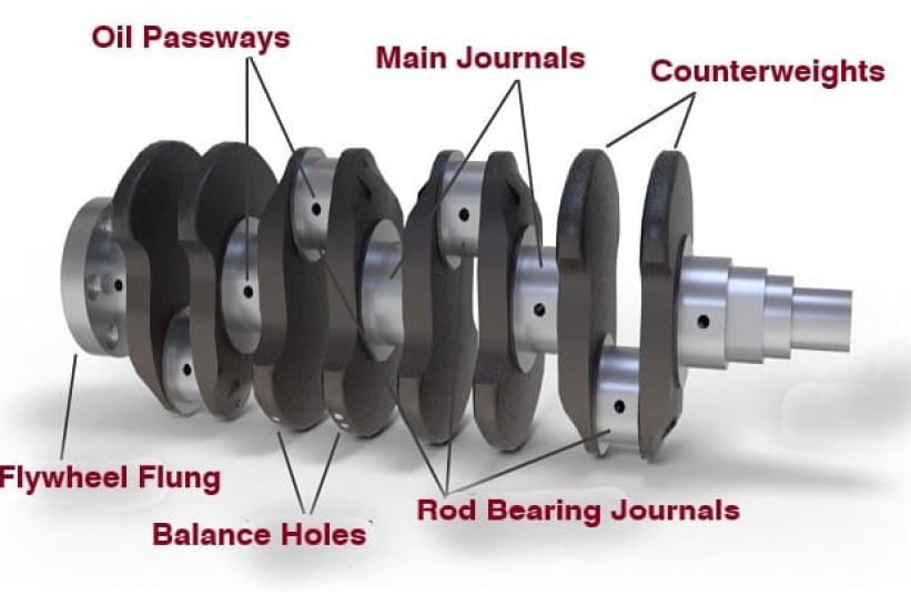
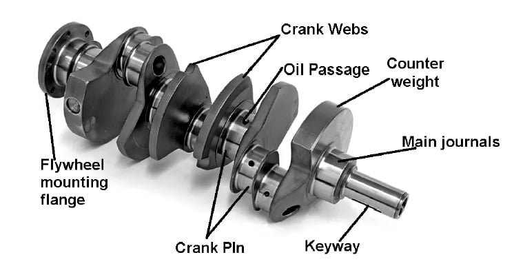
A crankshaft has following main parts :
- Crankpin
- Main Journals
- Crank Web
- Counterweights
- Thrust Washers
- Oil passage & Oil Seals
- Flywheel Mounting Flange
1. Crankpin
The crankpin is the part of crankshaft which allows it to connect with the connecting rod firmly.
Crankpin has a cylindrical surface to give the required rotative force to the big end of the connecting rod. They are also known as rod bearing journal, Connecting rod journal. It is placed offset from the axis of rotation as seen in the picture.
Some connecting rods have perforated oilways to spray lube oil onto the cylinder wall and for this the crankpins have a groove for supplying the oil to the connecting rod.
2. Main Journal
The portion of a crankshaft which rests on cylinder block is called main journal. The main journal bearing is attached to the engine block. It helps the crankshaft to rotate inside the engine block. It is also known as main bearing or journal bearing or plain bearing. To understand the working of main journal bearing please go to the link “Journal Bearing”
3. Crank Web
Crank web is the part of the crank which lies between the crankpin and the shaft or between adjacent crankpins. It connects the crankshaft to crankpin or the two adjacent crankpins.
4. Counterweights
A crankshaft faces a strong rotational forces and the whole mass rotates around the axis and also the piston applies force on it. Combination of all these forces can lead to misalignment in the structure. So to balance these forces we need an extra weight which balances the force and helps in making the engine faster and quieter. These balancing weights are called Counterweights.
5. Thrust Washers
Two or more Thrust washers are installed at specific positions along the length of the crankshaft to prevent the it from vertical movement.
These are placed between the web’s surface and the crankshaft’s seat in order to maintain a small clearance and prevent any lateral movement.
In some types of engines these washers are built as a part of the main journal bearing and in others, it is placed additionally.
6. Oil passage & Oil seals
The oil passage in the crankshaft transports oil from the main bearing journals to the big end journals. The hole is usually bored in the crank web. Oil can get between the journal and the bearing when the crankpin is in an upright position and combustion forces push the connecting rod downward.
The ends of the crankshaft are extended beyond the crankcase because of which there is a chance of leakage. In order to prevent oil from leaking, sealings are provided at both the ends.
There are two oil seals provided to prevent the leakage
- Front End Oil Seals : These are similar to the rear end oil seals and their failure is less destructive and are easily accessible. It is fitted behind the pulley and timing gear.
- Rear End Seals : They are fitted between the main journal and the flywheel. It is a synthetic rubbers lip seal.
7. Flywheel Mounting Flange
The flywheel is attached to the crankshaft through the flanges. One end of the crankshaft wheel has a large diameter as compared to the other which helps the flange face to attach the flywheel.
Construction of the Crankshaft
Crankshaft can be constructed by assembling from several pieces or can be monolithic i.e made in a single piece.
Crankshafts are made by forging a steel bar usually through roll forging or cast in ductile steel. Forged crankshafts are lighter in weight, more compact in dimensions and have better inherent damping.
Crankshafts can also be constructed by machining from billet ( a bar of high quality vacuum remelted steel).
What is the material used to produce crankshaft
Following are crankshaft material used for its construction:
- Cast Iron
- Carbon Steel
- Vanadium Micro-alloyed Steel
- Forged Steel
Function of Crankshaft
The front end of the crankshaft consist of gear or sprocket that operates the camshaft, vibration damper that is provided to reduce torsional vibrations. Also a fan belt pulley is there which drives the engine fan, water pump and generator through V-belt.
The rear or back end of the crankshaft has flywheel attached to it. Flywheel help to keep the engine running at constant speed during the dead strokes of the engine. To minimize the vibration, the crankshaft and the flywheel are balanced properly.
The number of main bearings depends on the type, design and size of the engine and cylinders. The more the number of main bearings, less is the possibility of vibration and any distortion in the crankshaft. It should be sufficient to provide support to the shaft and provide stiffness between each crankpin.
Types of Crankshaft
There are 7 types of crankshaft :
- Fully built crank shaft
- Semi built crank shaft
- Welded crank shaft
- Solid Single Piece crank shaft
- Forged crank shaft
- Cast crank shaft
- Billet crank shaft
1. Fully built Shaft
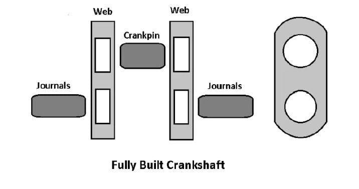
These types of crankshaft are made by creating the different parts separately and assembling them together. In such type of crankshaft all the parts are shrink-fitted after the fabrication process. These are mainly used in old types of engine.
Crank web, crankpin and the main journal are made separately and then the crankpin and main journals are machined and bored in the crank web.
The crank webs are then heated and fitted into the crankpins and journal holes. As it gets cooled, the diameter of the borehole fits properly and firmly.
2. Semi Built Shaft

Unlike fully built, in these types of crankshafts crank webs are forged completely and are then shrunk-fit to the main bearings.
The crankpins are machined in order to give a smooth finish. Two webs and crankpins are made in a single forging. With this method, the thickness of the crank webs are reduced . A hole is bored through the crankpin which helps in reducing the weight of whole structure without compromising with it’s strength.
These types of crankshafts are lighter and are capable of transmitting higher loads and can withstand high stresses.
3. Welded Shaft
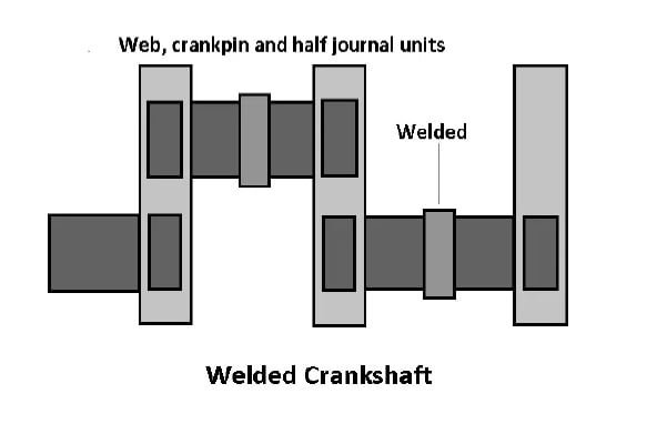
In these types of crankshafts, the crank web, crank pin and the main journals on both sides are forged in a single forging and then they are assembled together by welding. Submerged arc welding is used in construction of crankshaft.
After welding, the journals are made stress free and mechanised for smoothness. Because of the continuous grain flow, these webs can be made in smaller size resulting in a smaller crankshaft.
Reduced weight and thickness make these shafts more preferable to use.
4. Solid Single Piece Shaft
These types of crankshafts are created using a single-piece forging or casting process. They can be found in both low-speed and high-speed engines.
It is made up of several components and is made up of several parts bolted together on flanges that are integrated. This is to ensure that the load is maintained during firing and that cyclic tension is absorbed. The crankshaft can be stressed because of misalignment, torsional vibration, and axial vibration of the main bearings.
5. Forged Crankshaft
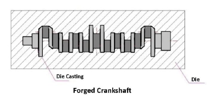
These cranks are far more durable than cast cranks. High-stress engines and some 16 valve engines often use forged cranks. They’re made in very distinct ways.
A set of dies is made to fit the crank’s approximate size. These dies are clamped in a massive hydraulic press with several tonnes of clamping force. The metal is pushed quite tightly once the die is closed.
These crankshafts are more robust and long-lasting. Heat treatment reacts differently in forged crankshafts, resulting in higher dimensional stability.
6. Cast Crankshafts
These types of crankshafts have been in use for a long time. They can be found in a variety of diesel and gasoline engines. In most cases, they are composed of malleable iron cast in a mould.
They are a popular choice among manufacturers since they are inexpensive to produce and perform effectively. Because the metal grain structure is uniform and random, the cast crankshaft can sustain loads from all directions.
7. Billet Crankshafts
A billet crank may be one of the best option. Typically Steel is used in the construction of such cranks. Nickel, chromium, aluminium, molybdenum, and other elements are among them.
Because of the shorter machining time of the crankshaft, billet cranks are well-known. Due to the consistent nature of the material, they also require minimal balance.
Working of Crankshaft
The crankshaft works on crank mechanism. The connecting rods are attached to the crankpins and cranks of a crank. It has a vibration damper that lowers the crank thrust. The counterweight on the crank is used to reduce the bending load on the crank.

A 4-stroke engine’s crankshaft functions as follows:
- The engine piston transmits its motion to the crankshaft via a connecting rod as it advances from TDC to BDC (downward stroke).
- The piston’s linear motion is converted to rotary motion by the crank, which is then transferred to the camshaft.
- When the camshaft rotates, the inlet valve opens, allowing the air-fuel combination to enter the combustion chamber.
- The piston travels upward (from BDC to TDC) when the combustion chamber fills with the air-fuel combination, compressing the mixture. The camshaft closes both the inlet and exhaust valves during this procedure. The first rotation of the crankshaft is completed when the compression process is completed.
- The igniting process occurs at the end of the compression process.
- The piston is forced downward by the heat emitted by the compressed mixture during the ignition process. This stroke is known as Power Stroke. During this piston moves downward, the reciprocating force is transferred to the connecting rod, which then sends it to the crankshaft.
- The flywheel is connected to one end of the crank. The crank receives the motion of the piston and sends it to the flywheel. This motion is stored in the flywheel, which then drives the vehicle wheels.
- The piston travels downward after the power stroke to discharge the exhaust gases. The camshaft receives the piston’s motion from the crank and opens the exhaust valve while the inlet valve remains closed during this procedure. The exhaust gases are pushed out of the combustion chamber by the piston.
- Two crank revolutions and one power cycle of a four-stroke engine are completed after the exhaust stroke. After that, the cycle starts all over again.
Imagine your legs pedaling a bicycle for a better understanding. Consider your legs as pistons and your pedals as a connecting rod in this scenario. The reciprocating movement of the piston is translated to a rotating motion of the crankshaft when you paddle it.
Faults in Crankshafts
Crankshaft faults are extremely uncommon. When the engine is subjected to harsh conditions, this happens. The engine components are solid and durable. However, they have certain fundamental flaws:
- Worn Journals
- Fatigue Failure
1. Worn Journals
It usually happens when there is insufficient oil pressure. When the crankshaft makes contact with the journal bearing surfaces, the clearance gradually increases and the oil pressure decreases.
Worn journals can create major engine difficulties if not properly cared for. The bearings are destroyed, and the engine is severely damaged.
2. Fatigue Failure
This happens when the continuous and repetitive force on the crankshaft causes it to break. This problem frequently arises on the fillet when the journal and the web are involved.
To avoid weak points that create fatigue cracks, the fillet must have a smooth surface. Magna-fluxing on the crankshaft can be used to check for cracks.
What Causes the Crankshaft to Break Down?
- Overheating: When the engine overheats, it can cause a variety of problems. The heat stored in the engine increases above the ambient temperature if the engine overheats owing to a faulty radiator, insufficient ventilation, or poor lubrication, and the plastic housing of the crankshaft sensor cracks or melts. The vehicle will not start in this instance. The sensor is unable to transmit data from the crankshaft to the computer for this reason.
- Wiring harness Fault : Contamination, debris, oil, or loose wiring in the wiring harness can cause issues such as loop, ground, or inappropriate voltage, among other things. These problems can cause problems with the electrical harness and cause the crankshaft to fail. Because dirt, oil, or loose wiring can wear out the wiring harness, cause voltage disruptions, or cause wear and tear on the wiring itself. This can cause the sensor to fail repeatedly.
- Timing Belt Failure: Due to regular wear and tear or collision, the timing belt might be damaged. This fouled timing belt loops around the crank, causing damage to a variety of minor components. The crank position sensor may be damaged as a result of the timing belt damage. The sensor and wiring harness may be damaged as a result of this.
Crankshaft Position Sensor
A crank sensor is an electrical device that monitors the position or rotational speed of the crankshaft in an internal combustion engine, both petrol and diesel.
Engine management systems employ this information to govern fuel injection, ignition system timing, and other engine characteristics. On petrol engines, the distributor had to be manually set to a timing mark before electronic crank sensors were available.
What does a Crankshaft Position Sensor do ?
The crankshaft position sensor’s primary function is to determine the crank’s position and/or rotational speed (RPM). The information sent by the sensor is used by Engine Control Units to control factors like ignition and fuel injection timing.
The crank sensor can be used in conjunction with a camshaft position sensor to monitor the engine’s piston-valve relationship, which is especially significant in engines with variable valve timing.
Signs of a Bad Crankshaft Position Sensor?
The most common symptoms of a damaged crankshaft position sensor are :
- Because of the excessive wear on the connecting rod bearings and the crankshaft main journal, the engine begins to knock.
- Due to crankshaft damage, the engine may produce a lot of noise.
- Because of a seizure, the vehicle’s engine may not start.
- Engine Stalling and Backfiring: When the crankshaft position (CKP) sensor fails, the engine stalls and backfires. The CKP sensor failure might cause the engine to shut down abruptly after starting without causing any problems.
- Excessive Engine Vibration: To guarantee stable power output, the CKP sensor monitors and limits the vibration created by the vehicle’s engine. Excessive vibration in your vehicle’s engine could be an indication of a damaged crankshaft.
- Cylinder misfire occurs when the CKP sensor is broken and the PCM does not get all of the essential data to deliver a spark to the correct combustion chamber. The cylinder fails as a result, and the engine loses power.
Reasons that may lead Crankshaft to break ?
- Water hammer, irregular combustion, and other factors might cause the crankshaft to break.
- Crankshaft damage can also be caused by defective shaft material.
- A sudden engine stall caused by a loose counterbalance, as well as gearbox failure, etc.
- Before being repaired, the shaft is mechanically damaged.
- Due to clutch failure, a malfunctioning flywheel, or a damaged vibration damper, there is unnecessary rotation and vibration.
- There hasn’t been enough work done on the crankshaft bearings.
- Material deterioration as a result of previous bearing failure and annealed bearing journals, among other things.
- As a result of early bearing failure or faulty repair work, the bearing journal has become soft (e.g., unnecessary regrinding).
- The engine’s commissioning did not follow the manufacturer’s recommendations.
- The improper bearing shell was used.
- The old bearing head bolts are used, or the torque is incorrect.
- Because the oil system is not pre-filled and pre-compressed, there is insufficient lubrication during commissioning.
- The connecting rod/main bearing caps were jumbled or crookedly installed.
- The bore size of the crankcase bearing inside the crankshaft was not tested or rebuilt after it was damaged.
- The oil filter, engine oil, and oil cooler were not changed when they should have been.
- The swarf that lingers in the engine oil circuit might cause the crankshaft to crack if the bearing is damaged.
How to Increase the Service life of the Crankshaft ?
Every engine parts needs to be maintained properly and regularly. Following are certain practices that can be followed to increase the service life of a Crankshaft:
- Engine bearings must be properly maintained.
- Proper lubrication of the crankshaft’s various sections.
- Ensure that the engine oil does not mix with the fuel or coolant.
- According to the manufacturer’s instructions, provide adequate oil to the engine.
- Avoid using oil that contains dirt or other contaminants.
- Ensure that the engine does not overheat.
- Engine maintenance and inspection on a regular basis.
- Use a crankshaft that is built of good, high-quality materials.
- On a regular basis, change the oil filter, engine oil, and oil cooler.
- Before installing the shaft, make sure it’s in good shape.
- Prevent mechanical overloading of the crankshaft due to water hammer, irregular combustion, and other factors.
What are the reasons that lead to Crankshaft Deflection?
Crankshaft has to bear a huge amount of stress which sometime may cause deflection in it. These are the reasons that may lead to crankshaft deflection :
- The piston’s reciprocating motion inside the combustion chamber.
- Because of the crankshaft’s twist and torsion.
- Crankcase explosion or fire
- Because of the power stroke. Because the piston applies a jerk force to the crankshaft after completing a power stroke in the engine, causing it to revolve faster.
- Grounding of the ship
Breaking of Crankshaft
The first factor here is the Fatigue. It implies that a material can fail as a result of repeated loading. When crankshafts spin, the loads reverse, causing the shaft to flex slightly. It’s similar to how you can break a coat hanger or wire by just bending it back a fourth, perhaps a dozen times.
A crankshaft has significantly less flex, therefore it takes millions of cycles to break it, but the failure mode is the same as a coat hanger. If a bearing supporting the crankshaft breaks due to a lack of lubrication, the deflection displacement each spin grows substantially, making failure more likely.
Another cause of a break at the rear of a crankshaft is an imbalanced flywheel/torque converter or a misaligned transmission. Another potential cause is a stress riser (nick in the finely ground finish) in the radius near to the bearing journal. The nick has the potential to turn into a crack that spreads swiftly.
Applications of Crankshaft
- The crankshaft controls the motions of all the valves in the Internal Combustion Engine’s suction, compression, ignition, expansion, and exhaust operations at the right cycle timings.
- The rotary motion generated by the connecting rods is received and sent to the flywheel.
- The reciprocating motion of the piston is converted into rotary motion by the crankshaft, which then moves to the vehicle wheels.
FAQs
Who invented crankshaft?
Al-Jazari in 1206
What are the types of crankshafts?
Following are the types of crankshaft :
1. Fully built crank shaft
2, Semi built crank shaft
3. Welded crank shaft
4. Solid Single Piece crank shaft
5. Forged crank shaft
6. Cast crank shaft
7. Billet crank shaft
Does the crankshaft turn the camshaft?
A chain or timing gear connects the crankshaft to the camshaft. This timing gear transmits the action of the crank to the camshaft. The camshaft utilizes the rotating motion provided by the crankshaft to open and close the inlet and exhaust valves.
Which engine doesn’t have a camshaft?
Since in 2 stroke engines inlet and exhaust takes place through ports. Therefore they don’t require cam to operate valves.
A crankshaft works on which mechanism?
Crank mechanism.
What is Crank / Crank Mechanism?
A crank is an arm that is mounted at a right angle to a spinning shaft and transmits or receives circular motion to the shaft.
Which type of bearing is used in crankshaft
Plain bearings or Journal Bearings are used in main bearings and connecting rod bearing.
What is the ratio of crankshaft and camshaft
The camshaft is attached to the crankshaft at a 1:2 ratio via the timing chain and sprockets, and thus spins once for every two crankshaft turns. Its job is to keep the intake and exhaust valves open at the right times while the piston moves through the four strokes.
Check Out Other Important Topics