
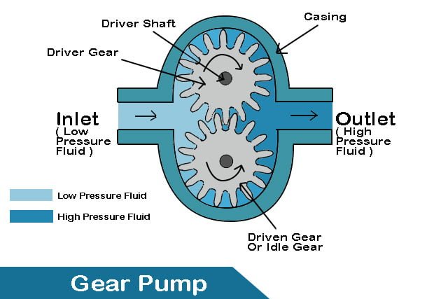
A Gear pumps is a type of positive displacement pump which which displaces liquids from suction to discharge side by meshing of toothed gear.
It uses two toothed gears ,shown, mess together ,supported by seperate shafts and are a close fit in casing.Generally,One gear is driven by the motor and other gear is driven by gear.In some cases, both shafts may be driven by motors.The shafts are supported by on bearing on each side of the casing.
Must read :- Centrifugal Pump
Gear pumps working
What is the principle of operations used in gear pumps
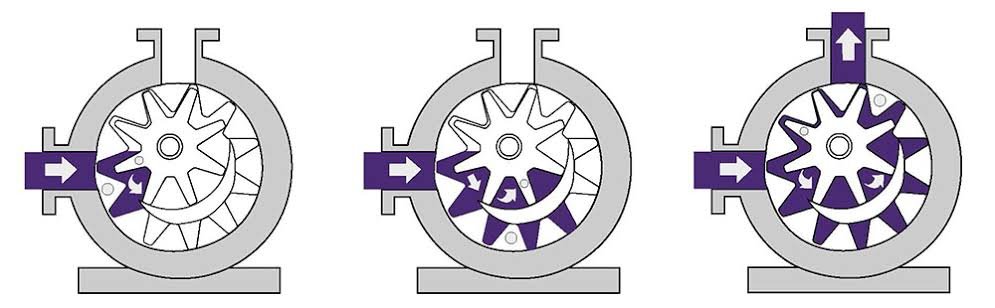
The gear pump work as,when pump is started the prime mover drive the shaft and the driving gear starts rotating. The driven gear which is in mesh with the driver gear also rotates as the driver gear rotates but in opposite direction.
As the both gear started rotating, the air or gas is trapped between each pair of consecutive teeth and the same is dragged along the casing from suction to discharge till no more air is left on the suction side.
Due to gear coming out of the mesh on inlet side of the pump,they create an expanded volume i.e vaccum.As the vacuum is created the liquid in the suction side get sucked towards the gear.or,liquid from tank will rise up into suction line under atmospheric pressure . After that sucked liquid gets trapped between gear and casing.
Then the trapped liquid between the casing and the gear teeth travels along with the rotation of gear teeth and moves from the suction side towards the discharge side.
As the teeth of the gear become interlocked in the outlet side of the pump ,and the volume is reduced and fluid is forced out under pressure.
Thus, pumping of liquid will occur.
Components or parts of Gear pumps
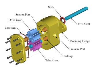
1.Drive gear :-The Drive gear is connected to the prime mover . The power from the prime mover is used to rotate it. The prime mover is motor.
2.Driven gear :- The driven gear is meshed with drive gear.As drive gear rotates ,driven gear is rotated in opposite directions.
3.Casing :- The driver and driven gears are both packed inside the gear pump’s casing.
4.Suction Side: The section of the gear pump from where fluid enters the gear pump. The Inlet Section is where low-pressure liquid enters the pump.
5.Discharge Side :- The discharge side of the gear pump is where pressurized fluid is delivered to the required area. The pump’s Outlet Section discharges high-pressure liquid.
6.Prime Mover: The prime mover in a gear pump is used to provide power to the shaft on which the driver gear is mounted. It could be an electric motor, an internal combustion engine, or manual labor.
7.Safety valve :-A safety valve or release valve is installed on the discharge side of the pump so that if excessive pressure is generated, it can be released and the pump is not damaged.
Applications of gear pumps
● Petrochemical :-They are used for crude oil, diesel oil, lube oil, pitch, and bitumen.
● Chemical :-They are also used to transport chemicals such as sodium silicate, mixed chemicals, acids, plastics, isocyanates, and other hazardous materials.
● Pulp and paper industry :-They are widely popular in the pulp and paper industries, where they are used to acid, lye, soap, black liquor, latex, kaolin, lime, and sludge.
● They are also used for adhesives, resins, ink and paint.
● Food:-The food industry uses them for a lot of tasty options,which include molasses, vegetable oils, pet food, vegetable fats, fillers, sugar, chocolate and cacao butter.
Advantages and Disadvantages of gear pump
1.Simple and Compact :-These pumps are very simple and compact with very few numbers of moving parts.
2.Maintenace cost :-The cost of maintenance is very less.
3.Cost :-The cost of the pump is also low.
4.Generate high pressure :-This pump can be used for generating very high pressure up to 3000 psi.
5.Pump high viscous fluid :-
It can be used to pump highly viscous fluids such as oils that centrifugal pumps cannot pump.
When pumping a high viscosity liquid like oil through the gear pump, the possibilities of leakage are extremely minimal. As a result, when pumping high viscous liquids, the efficiency of this pump improves.
6.Bi-directional:-It can run in both directions. Hence, a single pump can be used for both loading and unloading purposes.
7.Less Contamination :-This pump is very less sensitive to contamination.
8.Self priming :-The main advantages if this pump is, it is self priming.
Disadvantages
1.Fluids having solid particles cannot pumped,it is because of meshing of gear.
2.These pumps are noisy due to meshing of gear.
3.The size of pump is limited.It is not used for high flow rate.
Types of gear pump
1.External gear pump
External gear pump is a Type of positive displacement pump which displaces fluid from suction to discharge side through spaces available between casing and spaces of teeth by using meshing two teethed wheel.
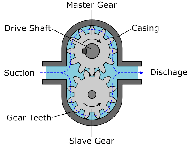
How does a external gear pump works ?
Un-meshing of gear takes place in auction side as prime mover rotates the drive gear.Due to un-meshing of gear Expansion of volume at the inlet of the pump.The expanded volume creates a vacuum which allow external pressure to push fluid into the pump.
As the gears rotates,the fluid available is trapped between the teeth of the gear and cavity wall of the casing.Thus, transfers the fluid from the inlet side of the pump to the outlet side. Tight clearances and the speed of rotation minimize fluid from internally leaking backwards.
As the teeth of the gear become interlocked in the outlet side of the pump ,and the volume is reduced and fluid is forced out under pressure
Applications of gear pump
- Chemical blending and compounding
- Used in various lube and fuel oils
- Polymers and solving agents
- Caustic and acidic fluids
- Hydraulic, farming and engineering applications
- Polymer metering and chemical extracts
- Low volume or transfer applications.
2.Internal gear pump
An internal gear pump is a positive displacement pump which displaces fluid from suction to discharge side by using two meshing gear are of different sizes with one rotating inside other.
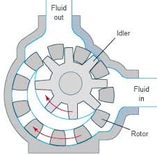
It has two gear :- 1.Internal gear 2.External gear
1.Internal Gear :-The larger gear is an internal gear called rotor .It has teeth projecting on the Inside.
2.External gear :- The smaller gear is External gear .It has teeth projecting outside.It is inside internal gear.It is called idler.
Note :- Within inside internal gear ,external gear is mounted off centre.
This is disesigned in such a way that they interlock ir mesh with each other at one point.
A pinion and bushing attached to the pump casing holds the idler in position.
A fixed crescent-shaped partition or spacer which fills the void which is created by the off-centre mounting position of the idler and acts as a seal between the inlet and outlet ports.
How does an internal gear pump works ?
When gears rotate then gears emerge from the mesh on the inlet side of the pump and it will create extended volume.
The liquid is flown into the cavities and surrounded by the gear teeth as the two gears stay to revolve opposing the partition and the casing sections.
When the teeth of the gear are interlocked on the pump discharge side, then the fluid volume will get decreased and the liquid is drawn out.
Applications of Internal gear pump
- Used in surfactants and soaps manufacturing
- Pigments, inks, and resins
- Used in food products like animal feed, cocoa butter, corn soups and in many
- Resins and Polymers
- Alcohols and solvents
- Asphalt, Bitumen, and Tar
- Polyurethane foam (Isocyanate and polyol)
- Glycol
Factors affecting efficiency of gear pump
In general, gear pumps are very efficient, especially in high-pressure applications.
Factors affecting efficiency of pump are :-
1.Clearances :-Geometric clearances at the gears’ ends and outer diameters allow for leakage and back flow. However, greater clearances can sometimes help minimize hydrodynamic friction and improve efficiency.
2.Backlash :-Fluid leakage is also possible due to high backlash between gears. This, however, helps to prevent lost energy from trapping fluid between gear teeth (known as pressure trapping).
Check Out Other Important Topics
Home IC Engine Electrical Important PDFs Boilers Synergy Maritime Exam Naval Arch Interview Questions Difference Between Types of Pumps Types of Valves MEO Class 4 Auxiliary Machines
Source :- Wikipedia
