
what is dial gauge ?
A dial gauge, also known as a dial indicator or dial test indicator, is a mechanical measurement tool used to measure small linear distances or displacements with high accuracy. It consists of a circular dial face with graduations and a needle or pointer that moves in response to the measured displacement.

It is commonly used in manufacturing, engineering, quality control, and maintenance applications where precise measurements are required. They offer advantages such as high accuracy, versatility, ease of use, and durability, making them valuable tools for various industries.
Must Read : Types Of Gauges
parts of dial gauge
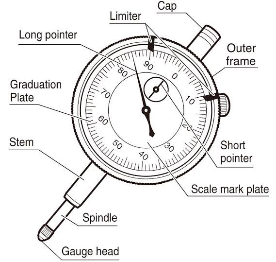
A dial gauge, also known as a dial indicator or dial test indicator, consists of several key parts that work together to perform accurate measurements. The main parts of a dial gauge include:
- Housing: The housing is the outer body of the dial gauge, typically made of metal. It provides protection and stability to the internal components.
- Dial Face: The dial face is a circular plate attached to the front of the housing. It contains graduations or markings that indicate the measurement readings. The dial face is usually divided into increments, such as thousandths of an inch or hundredths of a millimeter, allowing for precise measurements.
- Pointer: The pointer, also called a needle, is a thin, movable arm that extends from the center of the dial face. It rotates in response to the measured displacement and indicates the measurement value on the dial face. The pointer’s position corresponds to the magnitude and direction of the displacement relative to a reference point.
- Bezel: The bezel is a ring-shaped component surrounding the dial face. It often features a knurled or textured edge to facilitate easy gripping. The bezel may have a zero adjustment feature, allowing the user to set the pointer to zero or a reference position for calibration or comparative measurements.
- Contact Point or Probe: The contact point, located at the end of the dial gauge, is the part that makes physical contact with the object being measured. It can have various shapes and sizes, depending on the specific application. The contact point transfers the displacement to the internal mechanisms, resulting in the movement of the pointer.
- Stems and Gears: Inside the housing, there are internal mechanisms that translate the movement of the contact point to the rotation of the pointer. These mechanisms typically consist of stems, gears, and levers that amplify and transmit the displacement to the dial face.
- Mounting System: Many dial gauges come with a mounting system to securely position the gauge during measurements. This can include a magnetic base, clamps, or other attachment mechanisms that allow for stable and accurate positioning on a surface or fixture.
These are the primary parts of a typical dial gauge. However, it’s important to note that the specific design and additional features can vary depending on the brand, model, and intended use of the dial gauge.
dial gauge least count
Note : Dial Gauge Least Count (or dial indicator least count) is 0.01 mm for general dials and 0.001 mm for special purpose indicators.
The least count of a dial gauge, also known as the resolution or graduation, refers to the smallest increment that can be read or measured on the dial face. It represents the smallest unit of measurement that the dial gauge can accurately display.
The least count of a dial gauge is determined by the spacing or division between the graduations on the dial face. It varies depending on the design and specifications of the dial gauge. For example, a dial gauge may have a least count of 0.001 inch or 0.01 millimeters, indicating that it can measure displacements or variations with an accuracy of 0.001 inch or 0.01 millimeters.
To determine the least count of a specific dial gauge, carefully examine the dial face and identify the smallest division or graduation. This value represents the least count of that particular dial gauge model.
How to take reading with dial gauge
The working principle of a dial gauge, also known as a dial indicator or dial test indicator, involves the conversion of linear displacement into rotational movement, which is then displayed as a measurement reading on the dial face. Here’s a step-by-step explanation of how a dial gauge works:
- Initial Position: The dial gauge is initially set to a reference position, often called the zero position. This is typically achieved by rotating the bezel or using a zero adjustment feature to align the pointer with the zero mark on the dial face.
- Contact Point Engagement: The contact point or probe of the dial gauge is brought into contact with the object or surface being measured. The contact point is usually positioned perpendicular to the surface to ensure accurate readings.
- Displacement Detection: As the object or surface undergoes displacement or movement, it exerts a force on the contact point. This force is transferred to the internal mechanisms of the dial gauge.
- Mechanical Amplification: The internal mechanisms, consisting of stems, gears, and levers, amplify the small linear displacement detected by the contact point. These mechanisms convert the linear movement into rotational movement.
- Pointer Rotation: The rotational movement generated by the internal mechanisms is transmitted to the pointer of the dial gauge. The pointer rotates around the center of the dial face, indicating the magnitude and direction of the measured displacement.
- Measurement Reading: As the pointer rotates, it moves along the graduations or markings on the dial face. The position of the pointer relative to the graduations represents the measurement reading, typically in increments of thousandths of an inch or hundredths of a millimeter.
- Reading Interpretation: The user interprets the measurement reading based on the position of the pointer. Positive readings indicate an outward or upward displacement, while negative readings indicate an inward or downward displacement relative to the reference position.
By following these steps, a dial gauge provides a visual indication of the linear displacement or dimensional variation of the object being measured. The user can use this information for various applications, such as quality control, machine alignment, and precision measurements.
dial gauge reading with example
Sure! Let’s walk through an example to understand how to read a dial gauge measurement.
Suppose we have a dial gauge with a dial face divided into increments of thousandths of an inch. The pointer is initially set to zero at the reference position.
- Place the contact point or probe of the dial gauge against the object or surface you want to measure. Ensure the contact point is perpendicular to the surface.
- As you apply pressure or encounter a displacement, the contact point transfers this movement to the internal mechanisms of the dial gauge.
- The internal mechanisms amplify the linear displacement and convert it into rotational movement.
- The pointer of the dial gauge rotates, indicating the magnitude and direction of the measured displacement.
- Read the measurement value from the dial face where the pointer is pointing. The graduations on the dial face represent thousandths of an inch.
For example, let’s say the pointer is pointing to the 0.025 mark on the dial face. This means the dial gauge has measured a displacement of 0.025 inches (25 thousandths of an inch) from the reference position.
If the pointer is pointing to the -0.012 mark, it indicates a displacement of -0.012 inches (12 thousandths of an inch) inward or below the reference position.
It’s important to consider the direction of displacement and interpret the reading accordingly. Positive readings indicate outward or upward displacement, while negative readings indicate inward or downward displacement relative to the reference position.
Remember to set the dial gauge to zero before each measurement to ensure accurate readings and account for any variations or offsets.
By interpreting the measurement readings on the dial face, you can determine the dimensional variations, deflection, or displacement of the object being measured.
types of dial indicators
Certainly! Here are the types of dial indicators commonly used in various applications:
- Balanced Reading Dial Indicator: A balanced reading dial indicator, also known as a balanced dial indicator, features a dial face that displays both positive and negative values. The pointer can move in either direction from the zero position, allowing for easy and quick readings in both directions.
- Continuous Dial Indicators: Continuous dial indicators, as the name suggests, have a dial face that provides a continuous rotation of the pointer. This allows for continuous measurement readings without the need to reset or reposition the pointer during use. Continuous dial indicators are useful for applications where continuous monitoring of displacement or movement is required.
- Reversed Balanced Dial Indicators: Reversed balanced dial indicators have a dial face where the positive and negative values are reversed compared to a standard balanced reading dial indicator. The pointer moves in the opposite direction, providing readings in reverse polarity. These indicators are commonly used in applications where the direction of displacement needs to be considered or where reverse readings are preferred.
- Reversed Continuous Dial Indicators: Similar to reversed balanced dial indicators, reversed continuous dial indicators have a dial face where the positive and negative values are reversed. The pointer rotates in the opposite direction compared to a standard continuous dial indicator. They offer continuous readings with reversed polarity for specific measurement requirements.
- Plunger Dial Indicator: A plunger dial indicator, also known as a plunger gauge or depth gauge, is a type of dial indicator with a spring-loaded plunger as the contact point. It is designed to measure the depth, height, or position of a surface or object. Plunger dial indicators are commonly used in machining, inspection, and metrology applications.
- Lever Dial Indicator: A lever dial indicator, also known as a lever gauge or lever-type dial indicator, utilizes a lever mechanism to transfer linear displacement to rotational movement. It typically has a longer lever arm, allowing for higher magnification of the displacement. Lever dial indicators are often used in applications where a greater range or amplification of measurement is required.
These different types of dial indicators offer versatility and cater to specific measurement needs in various industries, such as manufacturing, machining, quality control, and engineering.
Applications of dial gauge
Dial gauges, also known as dial indicators or dial test indicators, are versatile measurement tools commonly used in various industries and applications. Here are some of the key applications of dial gauges:
1. Precision Measurements: Dial gauges are frequently used for precise measurements in manufacturing, engineering, and quality control processes. They can measure small linear distances with high accuracy, typically up to thousandths of an inch or hundredths of a millimeter.
2. Machine Setup and Alignment: Dial gauges are essential for aligning machine components and ensuring proper setup. They can measure runout, concentricity, and perpendicularity of machine parts, such as shafts, gears, and spindles. Dial gauges are often used in conjunction with alignment tools like surface plates and indicating bases.
3. Surface Flatness and Roughness: Dial gauges equipped with a special attachment called a surface probe can measure the flatness of surfaces and detect irregularities. They are useful for checking the flatness of machined parts, workpieces, or table surfaces.
4. Deflection and Deformation: Dial gauges can be employed to measure the deflection or deformation of structural components under load. By placing the gauge in proximity to the area of interest, it is possible to determine the extent of deflection or deformation and ensure that it falls within acceptable limits.
5. Gear and Bearing Backlash: Dial gauges are commonly used to measure the backlash in gears and bearings. By applying a specific force or rotating the gear, the dial gauge can detect any play or clearance between the mating components.
6. Automotive and Aviation Maintenance: Dial gauges play a crucial role in automotive and aviation maintenance, where precision measurements are necessary. They are used to check engine components, suspension systems, brake disc runout, wheel alignment, and other critical parameters.
7.Tolerance Checking: Dial gauges are utilized for verifying tolerances in machined parts. They help ensure that the dimensions of a workpiece meet the specified requirements and assist in identifying any deviations or errors.
8. Comparative Measurements: Dial gauges can be used for comparative measurements, where the goal is to compare the dimensions of two or more objects. By setting the dial gauge to a reference position, it is possible to measure the difference in dimensions between the objects being compared.
These are just a few examples of the applications of dial gauges. Their versatility and accuracy make them indispensable tools in industries that require precise measurements and quality control.
advantages of dial gauge
Dial gauges, also known as dial indicators or dial test indicators, offer several advantages that make them widely used in various industries. Here are some of the key advantages of dial gauges:
- High Accuracy: Dial gauges provide precise and accurate measurements, typically with a resolution of thousandths of an inch or hundredths of a millimeter. They are designed to have minimal measurement error, ensuring reliable and repeatable results.
- Versatility: Dial gauges are versatile tools that can measure various parameters such as linear distances, flatness, deflection, and more. They can be used in a wide range of applications, from manufacturing and engineering to quality control and maintenance.
- Easy to Read: Dial gauges feature a clear and easy-to-read dial face that displays the measured value. The graduations on the dial are usually large and distinct, allowing users to quickly and accurately read the measurements.
- Mechanical Operation: Dial gauges are mechanical instruments that do not require an external power source or batteries. This makes them reliable and always ready for use, without the need for charging or replacement of batteries.
- Robust and Durable: Dial gauges are built to withstand harsh working conditions and provide long-lasting performance. They are typically housed in a sturdy metal casing, making them resistant to impact and ensuring durability in industrial environments.
- Adjustable Positioning: Dial gauges often come with a flexible mounting system, such as a magnetic base or a clamp, allowing for easy and precise positioning. This adjustability enables users to place the gauge in the optimal position for measurement, enhancing accuracy and convenience.
- Comparability: It can be used for comparative measurements, making it possible to compare the dimensions of different objects. By setting a reference position, users can measure the difference in dimensions between two or more objects accurately.
- Cost-Effective: Compared to more advanced measurement instruments like electronic gauges or laser measurement devices, dial gauges are relatively cost-effective. They provide a good balance between accuracy and affordability, making them accessible to a wide range of users and industries.
Overall, the advantages of dial gauges include their high accuracy, versatility, ease of reading, mechanical operation, durability, adjustability, comparability, and cost-effectiveness. These factors contribute to their widespread use and popularity in various industrial and precision measurement applications.
disadvantages of dial gauge
While dial gauges offer several advantages, they also have a few limitations and disadvantages. Here are some of the key disadvantages of dial gauges:
- Limited Range: It has a limited measuring range compared to some other measurement devices. They are typically designed for measuring small linear distances or displacements. If you need to measure larger distances, you may need to use alternative tools or methods.
- Manual Operation: It require manual operation and physical contact with the object being measured. This can introduce a potential for human error, especially if the user applies inconsistent or excessive force while taking measurements. It also means that measurements may be affected by the user’s technique and skill.
- Subject to Parallax Errors: Parallax errors can occur when reading the dial gauge due to the viewing angle. If the user does not have a clear line of sight perpendicular to the dial face, the measurement reading can be inaccurate. Proper positioning and alignment are crucial to minimize parallax errors.
- Limited Resolution: While dial gauges offer reasonable accuracy, their resolution is limited compared to more advanced measurement devices like digital calipers or electronic gauges. This limitation may not be suitable for applications that require extremely precise measurements.
- Non-Digital Output: It provide analog readings on a dial face, which may not be suitable for certain applications where digital output or data recording is required. If you need to integrate the measurements into a digital system or perform automated data analysis, additional steps may be required.
- Fragility of Components: It consist of delicate internal components that can be sensitive to shocks, impacts, or mishandling. Rough handling or accidental drops can result in damage to the delicate mechanisms inside the gauge, affecting its accuracy or rendering it unusable.
- Limited Specialty Functions: While dial gauges are versatile tools, they may lack specific functions required for certain specialized measurements. For specialized applications or specific measurement tasks, alternative tools or more specialized equipment may be necessary.
- Environmental Sensitivity: It can be affected by environmental conditions such as temperature, humidity, or magnetic fields. Extreme temperatures or high humidity can impact the accuracy and performance of the gauge. Additionally, magnetic fields in the vicinity can interfere with the magnetic components often used in dial gauges, affecting their readings.
It’s important to consider these disadvantages when deciding whether a dial gauge is suitable for your specific measurement requirements. In some cases, alternative measurement tools or techniques may be more appropriate to overcome these limitations.
dial gauge least count
The least count of a dial gauge refers to the smallest measurement that can be read or detected on the gauge. It is an essential factor in precision instruments as it determines the accuracy of the measurements taken with the gauge.
Dial gauges are commonly used in various applications to measure small linear displacements or variations. They consist of a needle or pointer that moves along a calibrated scale when the gauge is subjected to a displacement or change in dimension.
To calculate the least count of a dial gauge, you need to know two things:
- The total travel or range of the dial gauge: This is the maximum distance the pointer can move along the scale.
- The number of divisions on the scale: This refers to the total number of equal divisions or increments on the scale.
The formula to calculate the least count is:
Least Count = Total Travel / Number of Divisions
Let’s take an example to illustrate this:
Suppose the total travel of the dial gauge is 10 mm (i.e., the pointer can move 10 mm along the scale). The number of divisions on the scale is 100.
Least Count = 10 mm / 100 divisions
Least Count = 0.1 mm
So, in this example, the least count of the dial gauge would be 0.1 mm, meaning it can measure displacements or changes as small as 0.1 mm with reasonable accuracy. Keep in mind that some dial gauges may have additional vernier scales or magnifying arrangements to further enhance precision.
Reference : https://www.sciencedirect.com/topics/engineering/dial-gauge