
Limits fits and tolerances are fundamental concepts in engineering and manufacturing that play a crucial role in ensuring the proper assembly, functionality, and interchangeability of mechanical parts.
When a machine is made up of different metal parts joined together and operates continuously, some parts may get damaged over time. When these damaged parts need to be replaced with new ones, the ease and stability with which the replacement can be done is called interchangeability of parts.
The interchangeability of parts is influenced by several factors, including limits, fits, and tolerances specified for the mating parts.
When designing and manufacturing machine parts, limits, fits, and tolerances play a crucial role. They help ensure that the parts fit together properly, allowing for smooth assembly and interchangeability.
In simpler terms, limits, fits, and tolerances are important considerations when creating machine parts. They ensure that damaged parts can be easily replaced with new ones, enabling the machine to continue functioning effectively.
Must Read : Snap Fit
what is limits fits and tolerances
When designing and manufacturing parts, engineers need to establish limits, which define the acceptable range of dimensions for a part. By setting lower and upper limits, engineers ensure that the actual size of the part falls within the specified range, meeting the desired specifications.
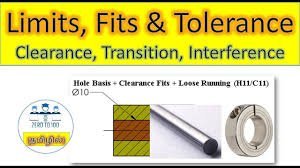
Fits, on the other hand, determine how parts fit together when assembled. Different fit types, such as clearance fit, interference fit, and transition fit, are selected based on the specific requirements of the assembly. Clearance fit allows for easy assembly and disassembly by providing a gap or clearance between the parts. Interference fit creates a tight connection, requiring force or additional operations to join the parts securely. Transition fit offers a compromise, providing a small amount of clearance for easier assembly while also ensuring some level of interference for improved alignment or stability.
Tolerances come into play to account for the inevitable manufacturing variations. They specify the allowable variation in dimensions, ensuring that even if the manufacturing process is not perfectly precise, the parts can still fit together properly. Tolerances consist of a nominal dimension, which represents the desired size, and a tolerance range that defines the acceptable deviation above and below the nominal dimension.
By carefully considering and defining appropriate limits, fits, and tolerances, engineers can achieve the desired functionality, performance, and interchangeability of mechanical parts in various applications. These concepts are vital for ensuring successful assembly processes, facilitating maintenance and repairs, and optimizing the overall performance and reliability of mechanical systems.
what is limit ?
Limits, in the context of engineering and manufacturing, refer to the allowable range of dimensions for a particular part. They establish the minimum and maximum values within which the dimensions of a part should fall to meet the desired specifications.

Here’s a detailed explanation of limits with examples:
Let’s consider a simple example of a cylindrical shaft. The design specification for the shaft requires its diameter to be 20 mm with a tolerance of ±0.2 mm. The limits for this dimension can be calculated as follows:
- Lower Limit (LL): The lower limit is obtained by subtracting the tolerance from the desired dimension. In this case, LL = 20 mm – 0.2 mm = 19.8 mm.
- Upper Limit (UL): The upper limit is obtained by adding the tolerance to the desired dimension. In this case, UL = 20 mm + 0.2 mm = 20.2 mm.
Therefore, for this example, the limits for the diameter of the shaft are 19.8 mm (LL) and 20.2 mm (UL).
These limits ensure that the actual diameter of the shaft during manufacturing falls within the specified range. If the diameter is less than 19.8 mm or greater than 20.2 mm, it would be considered out of tolerance and would not meet the required specifications.
Limits are crucial because they help ensure consistency and quality during the production process. By setting these boundaries, engineers can control the variability in dimensions and maintain the required standards for a part. It also allows for proper assembly and compatibility with other mating parts in a system.
In manufacturing, different parts may have multiple dimensions, and each dimension may have its own limits. For complex parts, limits can be defined for various parameters such as length, width, height, angles, clearances, or any other critical dimension specific to the part’s function.
By adhering to the defined limits, manufacturers can produce parts that are within acceptable tolerances, ensuring that the parts will fit correctly, function properly, and contribute to the overall performance and reliability of the system they are a part of.
what is fits ?
Fits, in the context of engineering and manufacturing, refer to the relationship between two mating parts when they are assembled together. The choice of fit determines how tightly or loosely the parts fit, and the amount of clearance or interference between them. Here’s a detailed explanation of fits with examples:
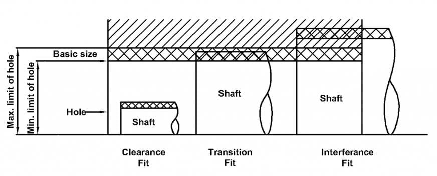
When two parts are designed to fit together, engineers consider various factors such as the function of the assembly, the desired level of precision, ease of assembly, and environmental conditions. Based on these considerations, different fit types are used. The three commonly used fit types are clearance fit, interference fit, and transition fit.
1. Clearance Fit:Characteristics: In a clearance fit, the maximum size of the hole is larger than the minimum size of the shaft. This results in a gap or clearance between the parts when assembled. Clearance fits are commonly used when easy assembly and disassembly are desired. They allow for relative movement between the parts and accommodate misalignment or thermal expansion.
- Example: Assembling a bolt into a nut is an example of a clearance fit. The bolt has a slightly smaller diameter than the hole in the nut, allowing for easy insertion and removal of the bolt.
2. Interference Fit: In an interference fit, the maximum size of the hole is smaller than the minimum size of the shaft. This causes the parts to be tightly joined when assembled. Interference fits provide a secure connection between the parts and prevent relative movement. They are commonly used when high torque transmission, improved alignment, or resistance to vibration is required.
- Example: Press-fitting a bearing into a housing is an example of an interference fit. The bearing has a slightly larger diameter than the housing hole, requiring force or heating/cooling methods for assembly.
3. Transition Fit: A transition fit offers a compromise between clearance fit and interference fit. The parts have a small amount of clearance, allowing for easier assembly, while still providing some degree of interference for improved alignment or stability. Transition fits are commonly used when a balance between easy assembly and secure fit is required.
- Example: Assembling a piston into a cylinder is a typical application of a transition fit. The piston has a slightly smaller diameter than the cylinder bore, resulting in a small amount of clearance for easier assembly while still providing some interference for proper sealing and stability.
The choice of fit type depends on the specific requirements of the assembly, such as the desired level of precision, load-bearing capacity, sealing capability, and thermal expansion considerations. Engineers select the appropriate fit type to ensure the proper functioning, reliability, and longevity of the assembled parts.
By carefully considering the fit type and dimensions, engineers can ensure that the parts fit together securely and perform their intended functions effectively, whether it is transmitting torque, guiding motion, providing sealing, or maintaining structural integrity.
what is clearance
Tolerance, in the context of engineering and manufacturing, refers to the allowable variation or deviation in the dimensions of a part from the desired or nominal dimension. It is an essential specification that ensures that even if the manufacturing process is not perfectly precise, the part will still function properly and fit within the intended assembly.

Here’s a detailed explanation of tolerance with an example:
Example: Let’s consider a cylindrical shaft with a desired diameter of 20 mm and a tolerance of ±0.1 mm.
In this example, the nominal or desired dimension is 20 mm. The tolerance specified is ±0.1 mm, which means that the actual diameter of the shaft can vary within a range of 20 mm ± 0.1 mm.
- Lower Limit: The lower limit (LL) is calculated by subtracting the tolerance from the nominal dimension. In this case, LL = 20 mm – 0.1 mm = 19.9 mm.
- Upper Limit: The upper limit (UL) is calculated by adding the tolerance to the nominal dimension. In this case, UL = 20 mm + 0.1 mm = 20.1 mm.
Therefore, for this example, the tolerance range for the diameter of the shaft is 19.9 mm to 20.1 mm.
Tolerance ensures that the dimensions of the manufactured part fall within this specified range. If the actual diameter of the shaft measures less than 19.9 mm or greater than 20.1 mm, it would be considered out of tolerance.
Tolerance is necessary because it accounts for the inherent variations that occur during the manufacturing process, including factors like machine tool accuracy, material properties, and environmental conditions. By specifying tolerances, engineers establish the acceptable range of variation to ensure that the parts will fit together properly, function as intended, and meet the required performance standards.
Tolerance is typically represented on engineering drawings using standard symbols and notations. These symbols indicate the nominal dimension and the allowable deviation above and below that dimension. The tolerance range can be specified for various dimensions such as length, diameter, width, angles, and more, depending on the specific requirements of the part.
types of tolerance
There are different types of tolerances used in engineering and manufacturing to specify the allowable variation in dimensions of a part. These types of tolerances provide specific information about the intended functionality and manufacturing requirements. Here are the commonly used types of tolerances:
- Unilateral Tolerance: In unilateral tolerance, the allowable variation is specified only on one side of the nominal dimension. It means that the part’s dimensions can deviate either above or below the nominal dimension, but not both. Unilateral tolerances are often used when the functionality of the part depends on a specific direction of variation.
Example: A hole with a diameter of 25 mm and a unilateral tolerance of +0.1 mm means that the actual hole diameter can range from 25 mm to 25.1 mm (deviation only on the positive side).
- Bilateral Tolerance: In bilateral tolerance, the allowable variation is specified on both sides of the nominal dimension. It means that the part’s dimensions can deviate in both positive and negative directions from the nominal dimension. Bilateral tolerances are commonly used when there is no preference for variation in a specific direction.
Example: A shaft with a diameter of 30 mm and a bilateral tolerance of ±0.05 mm means that the actual shaft diameter can range from 29.95 mm to 30.05 mm (deviation on both positive and negative sides).
- Limit Tolerance: Limit tolerance specifies the allowable variation by defining the lower limit (LL) and upper limit (UL) for a given dimension. The part’s dimensions must fall within this range to meet the specified tolerances. Limit tolerances are often used when the exact magnitude of variation is not critical, but rather the adherence to the prescribed range.
Example: A dimension with a limit tolerance of 10.0 mm to 10.2 mm means that the part’s dimensions must be within this range for the tolerance requirements to be satisfied.
- Geometric Tolerance: Geometric tolerances specify the allowable variation in geometric features such as form, orientation, location, and profile. They provide information about the shape, position, and relationship between multiple features on a part. Geometric tolerances are typically represented using specific symbols and control the geometric properties necessary for proper functioning and assembly of parts.
Example: A positional tolerance specifies the allowable variation in the location of a feature relative to a reference. It may indicate how much the feature can deviate from the desired position within a specified tolerance zone.
These types of tolerances ensure that the dimensions and geometric features of a part meet the required specifications, allowing for proper fit, function, and interchangeability. Engineers specify the appropriate type of tolerance based on the specific requirements of the part and the functionality it needs to fulfill in the overall system.
types of tolerance according to accuracy
Tolerance is categorized into two series, A series and B series, based on the accuracy requirements of the job:
A Series: The A series includes high-accuracy tolerance works. These tolerances are employed when precision is of utmost importance. Parts that fall within the A series have tighter tolerances, meaning the allowable deviation from the desired dimensions is smaller. These tolerances are used in applications where strict adherence to precise dimensions is critical, such as in precision instruments, aerospace components, and high-precision machinery.
B Series: The B series comprises general tolerance works. These tolerances are suitable for applications where a moderate level of precision is sufficient. Parts within the B series have relatively larger allowable deviations from the desired dimensions compared to the A series. B series tolerances are commonly used in everyday applications, including general machinery, automotive components, and consumer products.
The division into A series and B series provides a standardised approach for specifying tolerances based on the required level of accuracy. Engineers and manufacturers can select the appropriate series based on the specific needs and functional requirements of the job. This classification helps ensure consistency and clarity when communicating tolerance requirements, facilitating efficient and effective manufacturing processes.
difference between limit and tolerance
The terms “limit” and “tolerance” are commonly used in various fields and have different meanings depending on the context. Here are the general definitions and distinctions between the two:
Limit:
In mathematics and related disciplines, a limit refers to the value that a function or sequence approaches as it gets arbitrarily close to a particular point or as the independent variable approaches a certain value. Limits are used to describe the behavior and properties of functions or sequences near specific points or values. They are often denoted by symbols such as “lim” or “->” and are crucial in calculus and analysis.
In a broader sense, the term “limit” can also refer to a boundary or restriction beyond which something cannot go or exceed. For example, speed limits on roads define the maximum speed allowed, serving as a safety measure.
Tolerance:
Tolerance, on the other hand, generally refers to the acceptable deviation or variation from a specified standard or desired value. It is commonly used in engineering, manufacturing, quality control, and other technical fields to define the permissible amount of error or difference in measurements, dimensions, specifications, or performance of a product or system.
Tolerance is often represented as a range or interval around the target value, within which the item or process is considered to be acceptable. It allows for inevitable variations that may occur during manufacturing or operation while ensuring that the product or system still functions properly within the specified parameters.
In summary, while both “limit” and “tolerance” involve boundaries or restrictions, the former refers to the value approached by a function or the maximum threshold, while the latter relates to the permissible deviation from a desired value or standard.
Reference : http://ecoursesonline.iasri.res.in/mod/page/view.php?id=2799
