
Gate valve is a type of valve which restricts fully the flow of fluids. Or,valves which give full bore flow without change of directions .
As we know that valve is designed for controlling or interrupting the flow of fluid in pipeline.This is done by lowering,raising or rotating a disc in relation to the seating surface or by controlling the movement of a ball.
The valve disc here known appropriately as a gate,is moved right angles into the flow by a screwed spindle working in a nut.
In simple language, it is a type of valve that uses a gate or wedge type disk and the disk that moves perpendicular to the flow of fluid in piping to start or stop the flow of fluid.
Must read :- centrifugal pump
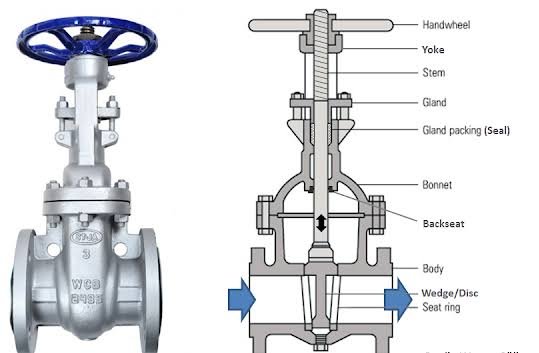
Gate valve diagram
What is a gate valve used for ?
In general, a gate valve is used to completely shut off flow of fluid in pipeline or, when fully open, to provide full flow in a pipeline. As a result, it can be used in either the fully closed or fully open position.
They are used as isolating valves in pipelines and should not be used as control or regulating valves. The operation of a gate valve is accomplished by rotating the stem clockwise to close (CTC) or clockwise to open (CTO). When you turn the valve stem, the gate moves up and down the threaded portion of the stem.
Gate valve working principle |How does a gate valve work ?
It works by lifting or pressing a rectangular or circular gate which connected by a stem by out of the path of the fluid by rotating the handle wheel clockwise and anticlockwise.
When the wheel with the handle is turned, the gate or wedge moves up and down across the flow of any fluid.
When you turn the handle wheel clockwise, steam and get move downward across the fluid flow, and the gate is squeezed between two seats.So that there is no fluid leakage when the valve is completely closed.
When you turn the handle Wheel anticlockwise, steam and fluid rise at the same time across the fluid flow. The valve is opened in the Chrome closed position, allowing fluid to flow through the Gate valve.
Gate will either open or closed.
Open gate means very low resistance or no resistance to the flow of any fluid.
Semi opening is not good because it causes erosion of the gate when fluid strikes.It also creates a lot of noise and vibration at the same time.
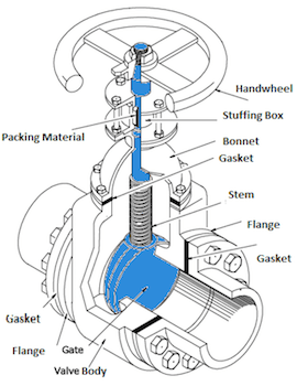
Gate valve parts name
Parts of gate valve are
1.Handwheel
2.Stuffing box
3.packing material
4.Bonnet
5.Gasket
6.stem
7.Flange
8.Gate/Disk
9.valve body
1.Handwheel
This is a wheel which is rotated clockwise and anticlockwise.
2.Stuffing box
Stuffing box :- A chamber in which the packing is compressed.
Valve stem packing / gland packing :-
3.Gland packing :-A gasket is required for a reliable seal between the stem and the bonnet. This is known as packing. This consist of following components
A.Gland follower, a sleeve that compresses the packing after it has been compressed by a gland into the so-called stuffing box.
B.Gland was a type of bushing that compressed the packing into the stuffing box.
C.A stuffing box is a chamber that compresses the packing.
D.Packing is available in a variety of materials, including Teflon®, elastomeric material, fibrous material, and others.
E.A backseat is a seating arrangement located inside the engine compartment. When the valve is fully open, it creates a seal between the stem and bonnet and prevents system pressure from building up against the valve pakking. In gate and globe valves, back seats are frequently used.
4.Bonnet:-
The bonnet is the cover for the opening in the body and is the pressure valve’s second most important boundary. Bonnets, like valve bodies, come in a variety of styles and models.
A bonnet, which serves as a cover for the valve body, is made of the same material as the body. It is typically attached to the body via a threaded, bolted, or welded joint.During manufacture of the valve, the internal components, such as stem, disk etc., are put into the body and then the bonnet is attached to hold all parts together inside
The attachment of the bonnet to the body is considered a pressure boundary in all cases. This means that the weld joint or bolts connecting the bonnet to the body are pressure-retaining components. Valve bonnets, while necessary for most valves, are a source of concern.
Bonnets can complicate valve manufacturing, increase valve size, account for a significant portion of valve cost, and be a source of potential leakage.
5.Gasket:-It is fitted between body and bonnet.
6.Stem:-
The valve stem is responsible for the proper positioning of the disk and provides the necessary movement to the disc, plug, or ball for opening or closing the valve. On one end, it is connected to the valve handwheel, actuator, or lever, and on the other end, it is connected to the valve disc. The disc in a gate or globe valve must move linearly to open or close the valve, whereas the disc in a plug, ball, or butterfly valve must rotate to open or close the valve.
Stems are typically forged and threaded or otherwise connected to the disk. A fine surface finish of the stem is required to prevent leakage in the area of the seal.
7.Flange :-It is for tightening the gland with nut.
8.Gate/Disk :-
Depending on its position, the disc allows, throttles, or stops flow. In the case of a plug or a ball valve, the disc is referred to as a plug or a ball. The disk is the third most important primary pressure boundary. When the valve is closed, full system pressure is applied across the disk, and as a result, the disk is a pressure related component.
To provide good wear properties, disks are typically forged and, in some designs, hard surfaced. Most valves are named after the shape and design of their disks.
9.Valve body :-
The primary boundary of a pressure valve is the valve body, also known as the shell. Because he is the framework that holds all the parts together, he is the most important component of a valve assembly.
A valve’s body, or first pressure boundary, resists fluid pressure loads from connecting piping. It accepts inlet and outlet piping via threaded, bolted, or welded connections.
The valve-body ends are intended to connect the valve to the piping or equipment nozzle via various end connections, such as butt or socket welded, threaded, or flanged.
Valve bodies come in a variety of shapes and sizes, and each component serves a specific purpose and is made of a material appropriate for that purpose.
10.Valve Seat
The seating surface for the disk is provided by the seat or seal rings. There may be one or more seats on a valve. A globe or swing-check valve typically has one seat that forms a seal with the disc to stop the flow. A gate valve has two seats, one on the upstream side and the other on the downstream side. A gate valve disc has two seating surfaces that make contact with the valve seats to form a seal that stops the flow.
To improve the wear resistance of the seal rings, the surface is frequently hard-faced by welding and then machining the seal ring’s contact surface. When the valve is closed, a fine surface finish of the seating area is required for good sealing. Seal rings are not typically considered pressure boundary parts because the body’s wall thickness is sufficient to withstand design pressure without relying on the thickness of the seal rings.
What are the types of gate valve ?
Gate valves types are classifieds in three ways :-
1.Tyes of disk
A.Sokid Taper wedge
B.Flexible wedge
C.Split or parallel disk wedge
2.Types of Body Bonnet Joint
A.Screwed Bonnet
B.Bolted-Bonnet
C.Welded-Bonnet
D.Pressure-Seal Bonnet
3.Types of Stem movement
A.Rising Stem or OS & Y Type (Outside Stem and Screw Type)
B.Non-rising Stem type
On basis of types of disk
1. Solid taper wedge :-
Because of its simplicity and strength, the solid wedge is the most common & widely used disk type. A solid wedge valve can be installed in any position and is suitable for nearly all fluids. It is also applicable in turbulent flow.
However, it does not refer to a change in seat alignment caused by pipe loads or thermal expansion. As a result, this type of disk design is the most vulnerable to leakage. When used in high-temperature service, solid wedges are subject to thermal locking.
Thermal locking is a phenomenon in which a wedge becomes stuck between the seats due to metal expansion. Solid-wedge gate valves are typically used in low-pressure, low-temperature applications.
2.flexible wedge
The flexible wedge is a solid disk that is one piece with a cut around the perimeter. The size, shape, and depth of these cuts vary. A shallow, narrow cut on the wedge perimeter reduces flexibility while maintaining strength. A cast-in recess or a deeper and wider cut on the wedge perimeter provides more flexibility but reduces strength.
This design improves seat alignment and provides improved leak tightness. It also improved performance when thermal binding was possible. Wedge pliability In steam systems, gate valves are used.
Thermal expansion of the steam line can cause valve body distortion, which can lead to thermal blinding. The flexible gate allows the gate to flex as the valve seat compresses due to steam pipeline thermal expansion, preventing thermal blinding.
The disadvantage of flexible gates is that line fluid accumulates in the disk. These can cause corrosion and eventually weaken the disk.
3.split or parallel disk
wedge cut in half The disk is made up of two solid pieces that are held together by a special mechanism. Images show the same thing. In the event that one-half of the disk is misaligned, the disk is free to adjust itself to the seating surface. The split disk can be in the form of a wedge or a parallel disk.
Since parallel disks are spring-loaded, they are always in contact with the seats and provide bi-directional sealing. The split wedge can handle noncondensing gases and liquids at both normal and high temperatures.
Even if the valve is closed when a line is cold, the disk’s freedom of movement prevents thermal binding. This means that when a fluid heats a line and causes it to expand, it does not cause thermal blinding.
On basis of stem movement
1.rising
The stem of a rising stem valve rises when the valve is opened and falls when the valve is closed. As shown in the image. The threaded portion of the stem is in contact with the flow medium in an inside screw design, and when the valve is opened, the handwheel rises along with the stem.
In the case of an outside screw design, only the smooth portion of the stem is exposed to the flow medium, and the stem rises above the handwheel. This valve is also known as an OS & Y valve. Outside steam and York are abbreviated as OS & Y.
2.Non-rising stem type
A non-rising stem type has no upward movement of the stem. The valve disk is internally threaded. When the stem is rotated, the disc moves along it like a nut. The image is visible. The stem threads of this type of valve are exposed to the flow medium.
As a result, this design is used in situations where space is limited and the flow medium does not cause erosion, corrosion, or wear and tear to the stem material. An insider screw valve is another name for this type of valve.
On basis of body bonnet joint
1.Screwd bonnet
Screw-in bonnets are the most basic to build. They are commonly used in small size valves and provide a long-lasting leak-proof seal.This is the most basic design available, and it is used for low-cost valves.
2.Bolted
Bolted bonnets seal larger valves and higher pressure applications. The bonnet and valve body are flanged and bolted together in this configuration.
This is the most common design and is found in the majority of gate valves. A gasket is required to seal the joint between the body and the bonnet.
3.welded
A union nut holds the union bonnet in place. The union nut sits on the lower edge of the bonnet and screws into the threads of the valve body. This type of design ensures that the leak-proof seal created by the nut is not harmed by frequent removal of the bonnet. As a result, union bonnets are commonly used in applications that require regular inspection or maintenance.
This is a popular design that does not require disassembly. They weigh less than their bolted-bonnet counterparts.
4.pressure gate seal
Pressure seal gate valves are ideal for high-pressure applications (more than 15 MPa). Internal pressure is used in this type of construction to create a better seal. A downward-facing cup is inserted into the valve body of pressure seal bonnets. When internal fluid pressure rises, the cup is forced outward, improving the seal.
This type is commonly used in high-pressure, high-temperature applications. The greater the force on the gasket in a pressure-seal valve, the greater the pressure in the body cavity.
Application of gate valve
Applications of gate valve :-
1.Socket or butt welding end gate valves with are commonly used in air, fuel gas, feedwater, steam, lube oil, and other systems. Threaded-end gate valves are suitable for use in air, gaseous, and liquid systems.
2.Concerns for leakage from threaded connections can be addressed by seal welding the threaded connection or using thread sealants, as appropriate. Flanged gate valves are commonly used in low-pressure and low-temperature systems, such as fire protection system water piping or water distribution pipelines.
Gate valves are used in a variety of industrial applications, including oil and gas, pharmaceuticals, manufacturing, automotive, and marine.
On ship
Non-rising stem gate valves are very popular on ships, in underground applications, or where vertical space is limited because they do not take up extra space. Gate valves can be used in high-temperature and high-pressure environments. They are commonly found in power plants, water treatment plants, mining, and offshore applications.
What is the Advantages and disadvantages of gate valve
Advantage of gate valve
1.Fluid resistance :-Gate valves have very low fluid resistance. The straight inner media channel of the body allows the medium to flow directly through the valve without changing direction, resulting in minimal fluid resistance. As a result, the flow’s path is clear.
2.Energy efficient :-Gate valves are an energy-efficient valve option, as the movement direction or ram is perpendicular to the media flow direction. As a result, less power is consumed when opening or closing the gate valves in comparison to globe valves. Due to their energy-efficiency, they help reduce total ownership cost.
3.Simple body :-Gate valves have a relatively simple body. As a result, they are easier to operate than isolation valves with more complex designs.
4.Dual flow direction / Bidirectional :-
Gate valves are capable of being used in any direction in a circuit. In other words, their media flow is unobstructed in all directions of the valve body, and they are not affected by the directional flow of the medium. As a result, they are ideal for use in pipelines where the flow direction varies depending on the medium.
5.Minimal erosion :-When compared to other valve options, gate valves typically have less erosion on their sealing surface when fully open. The tight seal function of the valve is largely responsible for the valve’s minimal erosion.
6.Minimal pressure loss :-Gate valves have a low pressure loss due to the laminar flow they provide. When pressure loss can be reduced, it is always beneficial.
Disadvantage of gate valve
1.They cannot be quickly opened and closed. The shaft should be rotated as many times as the full open revolution number to fully open or close wheel or gearbox actuators. The pitch is equal to the total number of open revolutions.
2.Large amounts of space are required for assembly, startup, and maintenance.
3.The slow movement of the slide in the fully closed position causes a high flow speed. Vibration and collision cause abrasion and deformation in the seating surfaces, and friction damages the surface.
4.Leakages in gate valves occur in systems where the high-temperature changes irregularly due to the load in the pipe at the valve end.
5.Seating surface repair and maintenance are difficult at the workplace.
People also ask
What is gate valve used for?
A gate valve is typically used to fully halt fluid flow or, when fully open, to allow full flow in a pipeline. As a result, it can be utilized in either the totally closed or fully open configurations. A gate valve is made up of a valve body, seat, and disc, as well as a spindle, gland, and wheel that is used to operate the valve.
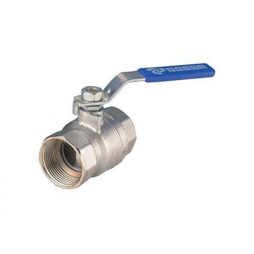
What is the difference between a gate valve and a ball valve ?
The primary difference is in the method of operation. To open/close the orifice, a gate valve moves a solid disk up and down. To open/close the valve, a ball valve rotates a ball (the orifice) with a bore in it 90 degrees.
is gate valve better than ball valve ?
Ball valves are more effective at forming a tight seal and have greater reliability and longevity than gate valves, but they are more expensive. They are frequently used in shutoff and control applications. Because ball valves can open and close instantly, they are more likely than gate valves to cause water hammer.
Check Out Other Important Topics
Home IC Engine Electrical Important PDFs Boilers Synergy Maritime Exam Naval Arch Interview Questions Difference Between Types of Pumps Types of Valves MEO Class 4 Auxiliary Machines
External Source :- wikipedia
[…] Read :- Gate valve parts |Working principle |Types […]