Foundry Tools And Equipment – List, Names & Images

Foundry tools and equipment may be classified into three groups, namely, hand tools, flasks, and mechanical tools.

1. Hand Tools

Hand Tools :- The hand tools uses are fairly numerous. A brief description of the most important tools is given here.

1. Shovel

A shovel mixing and tempering moving the sand from.

2. Riddle

A riddle, consists of a circular or fitted with a standard shown in Fig. 11.34. It is materials such as nails, wood, etc., from the moulding sand. Both hand and power riddles are available, the latter being used where large volumes of sand are to be riddled.

3. Sprue pin

Sprue foundry tools are a tapered (Fig. 11.35) pushed through the cope to the joint of the mould. As the peg is withdrawn it removes the sand, leaving an opening for the metal. This opening is called the sprue through which the metal is poured. The sprue pin forms the riser pin.

4. Bellow

Bellows are used to blow loose particles of sand from the pattern and the mould cavity. A hand blower is shown in Fig. 11.36.

Moulding machines are also provided with a compressed air jet to perform this operation.

5. Rammer

Hand rammer (Fig. 11.37) foundry tools are a wooden tool used for packing or ramming the sand into the mould. One end, called the peen, is wedge shaped, and the opposite end, called the butt, has a flat surface. Floor rammers are similar in construction but have long handles. Pneumatic rammers are used in large moulds saving considerable labour and time.

6. Trowel

A trowel consists of a metal blade fitted with a wooden handle (Fig. 11.38). Trowels are employed in order to smooth or sleek over the surfaces of moulds. A moulder also uses them in repairing the damaged portions of a mould. The usual trowel is rectangular in shape and has either a round or square end.

7. Slick

It is a small double-ended tool having a flat on one end and a spoon on the other end (Fig. 11.39). This tool is also made in a variety of shapes. The type most commonly used is the oval spoon. Slicks are used for repairing and finishing small surfaces of the mould.

8. Lifter

Lifters are made of thin sections of steel of various widths and lengths with one end bent at right angles as shown in Fig. 11.40. They are used to clean and finish the bottom and sides of deep, narrow openings in moulds.

9. Strike-off bar

The strike-off bar is a piece of metal or wood with a straight edge (Fig. 11.41). It is used to strickle or strike-off excess sand from the mould after ramming to provide a level surface.

10. Swab

A simple swab is a small brush foundry tools having long hemp fibers. A bulb swab has a rubber bulb to hold the water and a soft hair brush at the open end. A bulb swab is shown in Fig. 11.42. Swabs are used for moistening the sand around a pattern or for applying paint.

11. Gate Cutter

It is a small piece of tin plate shaped as shown in the figure. This serves as a tool for cutting gates and runners in the mould.

12. Mallet

A raw hide mallet is used to loosen the pattern in the mould so that it can be withdrawn without damage to the mould.

13. Vent rod

A vent rod or wire, as shown in Fig. 11.45, is used to make a series of small holes to permit gases to escape while the molten metal is being poured.

14. Draw spike or screw

The draw spike is a pointed steel rod, with a loop at one end. These foundry tools are used to rap and draw patterns from the sand. Fig. 11.46 illustrates two kinds of draw spikes. The draw spike is threaded on the end to engage metal patterns.

15. Rapping plate

A rapping or lifting plate, as shown in Fig. 11.47, is used to facilitate rapping and lifting of the pattern from the mould. The plate must be firmly attached to the pattern by long screws or even bolts in larger patterns. The moulder places a draw spike in the rapping hole and raps it to loosen the pattern, then fixes draw screws into the screw hole on the plate.

16. Pouring weight

A pouring weight is simply a plate of cast iron with a cross-shaped opening cast in it to give considerable liberty in placing the runner in the mould. It is used on the top of a mould for giving a weight to prevent the pressure of the liquid metal from forcing the mould apart causing a run-out.

17. Gaggers

Gaggers, sometimes called lifters, are iron rods bent at one end or both ends (Fig. 11.48). They are used for reinforcement of sand in the top part of a moulding box, and to support hanging bodies of sand.

18. Clamps

Clamps (Fig. 11.49) are foundry tools used for holding together the cope and drag of the completed mould to prevent he cope from floating or rising when the metal is introduced into the mould.

19. Spirit level

The spirit level in Fig. 11.50 is used by the moulder to ensure that his bed of sand moulding box or moulding machine table is horizontal

20. Moulding board and bottom board

A moulding board is a smooth wooden board on which the flask and patterns are placed when the mould is started. When the mould is turned over, the function of this board is ended the mould is placed on a similar board, called a bottom board, which acts as a support for the mould until it is poured.

2. Moulding Boxes

Another group of foundry tools are Moulding Boxes. Sand moulds are prepared in specially constructed boxes called flasks. The purpose of the flask is to impart the necessary rigidity and strength to the sand in moulding. They are usually made in two parts, held in alignment by dowel pins. The top part is called the cope and the lower part the drag.

If the flask is made in three sections, the centre is called the cheek (Fig. 11.3). These flasks can be made of either wood or metals depending upon the size required and the purpose the flasks must serve. Metal flasks are used when production is large, but when only a few castings are needed and a special flask must be obtained, the wooden flask is the most economical.

Two types of flasks are used in a foundry: (1) the snap flask, and (2) the tight or box flask. A snap flask (Fig. 11.51) is made with the hinge on one corner and a lock on the opposite corner so that the flask may be removed from the mould before it is poured. The snap flask is of advantage in that many moulds can be made for the same pouring from a single flask.

The tapered slip flask is another type of removal flask. It has rigid corners but the sides have a smooth inside surface and a 5-degree taper to allow the flask to be removed upward.

A box flask shown in Fig. 11.52 must remain in the mould until the pouring operation is completed. These boxes are usually made of metal and are very suitable for small and medium sized moulding.

A typical wooden moulding box is shown in Fig. 11.53. The side timbers are continued beyond the ends of the box to form two handles at each end. The sides are held together by strong cross timbers, reinforced with bolts. This is easier to handle and may be employed for large moulding.

3. Mechanical Tools

The third group of foundry tools are Mechanical Tools. The mechanical tools in the foundry include the many types of moulding machines that will ram the mould, roll it over, and draw the pattern. Besides, there are power operated riddles, sand mixers, sand conveyors, etc.

The mould is even poured and shaken out mechanically, and the casting is taken by machine to the cleaning department. The amount of mechanisation, however, varies considerably from one foundry to the other. Mass-production foundries making large quantities of relatively few types of castings are in a position to mechanise more completely than the job-shop foundries.

These were list of different types of foundry tools and equipment. Their work has also been mentioned. Hope you enjoyed the article. Gives your feedback in the comment section.

Check Out Other Important Topics

Plant Layout – Types, Objectives, Principles, Advantages

Types of Punches – Uses, Working, Applications, Pictures

Types of Dies – Classification, Uses, Pictures

Types of Rivets – Working & Their Uses [with Images]

Types of Fasteners – Uses & Examples [with Pictures]

Foundry Tools And Equipment – List, Names & Images

IC EngineImportant PDFsBoilersSynergy Maritime ExamNaval ArchMEO Class 4
Interview QuestionsDifference BetweenTypes of PumpsAuxiliary MachinesTypes of ValvesHome

Group Technology (GT) – Definition, Layout, Benefits

The article covers What is group technology, Layout, benefits, advantages and disadvantages.

What is Group Technology ?

Group technology, or GT, is a manufacturing technique in which parts with similar geometry, manufacturing process, and/or functions are manufactured in a single location using a small number of machines or processes. It is based on the general principle that many problems are similar, and that by grouping similar problems, a single solution to a set of problems can be found, saving time and effort.

Define Group Technology

Group technology is an important technique in the planning of manufacture that allows the advantages of product line organization to be obtained in what otherwise would be jobbing or batch manufacture. This technique identifies the sameness of parts, equipment or processes. Machines are grouped according to the routing required for a
family of parts rather than by their functions.

By using this technique, production planning and control functions are also simplified as the group of machines can be treated as one work center, thereby decreasing the number of work centers and simplifying the routing of parts. Waiting time is reduced significantly and work center utilization in improved.

It offers its greatest benefits when it is extended to all phases of production and production preparation including drafting and part programming for NC machine.

Group Technology Layout

One of the most popular types of hybrid layouts is group technology (GT) or cell layouts. It has the advantage of bringing the efficiencies of a product layout to a process layout environment. Group technology is the process of creating groupings of products based on similar processing requirements.

Group Technology

Objectives of Group Technology

  1. Reduce average lot size
  2. Increase part variety
  3. Increase variety of materials
  4. Achieve close tolerance
  5. Improve scheduling
  6. Reduce tooling
  7. Increase equipment utilization

Advantages of Group Technology

The generally accepted benefits of group technology are :

  1. Reduction in setting up times and cost.
  2. Reduction in material handling costs.
  3. Reduction in inventory cost and thus reduction of lot size.
  4. Reduction in throughput time.
  5. Reduction in work-in-progress.
  6. Reduction in planning cost and simplifying the documentation and administration of the process planning function.
  7. Simplified estimating, accounting and work man­agement.
  8. Output is improved due to improved resource utili­zation.
  9. Improved quality and less scrap.
  10. Smaller variety of tools, jigs and fixtures.
  11. Better space utilization
  12. Robots can be easily used for material handling.

This technique, along with good general management practices, therefore has a large contribution towards improving productivity in general and reducing inventory cost in particular.

Disadvantages of Group Technology

  1. The Additional cost of implementation of this system.
  2. The rate of change in product range and mix.
  3. Difficulties with out-of-cell operations.
  4. Coexistence with non-cellular systems.
  5. Involves less manufacturing flexibility.
  6. Increases the machine down time as machines are grouped as cells which may not be functional throughout the production process.

Uses of Group Technology

A classification system can be used to easily follow a GT technique. There are numerous parts in any assembly. These various parts can be classified into three broad categories, namely

1. Standard and proprietary parts (like nuts, bolts, screws, keys, washers, etc.)

2. Similar parts (like shafts, gears, bearings, levers, etc.)

3. Product specific parts (like gear box, bed, saddle, etc.)

It should be noted that the group technology is not concerned with categories I and (iii), but rather with category (ii). The goal is to group the range of parts under category (ii) in some way for manufacturing purposes.

Several classification systems have been developed, and one must carefully consider the system based on his needs. A company with a wide range of products requires a complex detailed system, but the same is not true for one with a limited range. Provision should always be made for future likely growth, and the classification system chosen should keep this requirement in mind.

Hope you enjoyed reading this article about the Group Technology. You can give your feedbacks in the comment below.

Check Out Other Important Topics

Plant Layout – Types, Objectives, Principles, Advantages

Types of Punches – Uses, Working, Applications, Pictures

Types of Dies – Classification, Uses, Pictures

Types of Rivets – Working & Their Uses [with Images]

Types of Fasteners – Uses & Examples [with Pictures]

IC EngineImportant PDFsBoilersSynergy Maritime ExamNaval ArchMEO Class 4
Interview QuestionsDifference BetweenTypes of PumpsAuxiliary MachinesTypes of ValvesHome

Industrial Disputes Act 1947 – Objectives, Purpose, Pdf, Notes

In this article we will discuss about the Industrial Dispute Act 1947, it’s provisions and details of enactment. At the end you can download pdf as a note given as Industrial Disputes Act 1947 pdf.

The Industrial Disputes Act 1947 is applicable in whole of India. This Act is a replacement of Trade Disputes Act of 1929. The Trade Disputes Act imposed certain restraints on the right of strike and lockout in public utility Services but lacks any provision for the settlement of Industrial Disputes, either by reference to a Board of Conciliation or to a Court of Inquiry. In order to remove this deficiency, the Industrial Disputes Act 1947 was passed.

This act is the main legislation for investigation and settlement of all industrial disputes. The Act enumerates the contingencies when a strike or lock-out can be lawfully resorted to, when they can be declared illegal or unlawful, conditions for laying off, retrenching, discharging or dismissing a workman, circumstances under which an industrial unit can be closed down and several other matters related to industrial employees and employers.

What is Industrial Dispute Act 1947 ?

Industrial Disputes Act 1947 is an act to make provision for the investigation and settlement of industrial disputes, and for certain other purposes.
And it is expedient to make provision for the investigation and settlement of industrial disputes, and for certain other purposes hereinafter appearing.

When it came under force ?

Enacted on 11 March 1947 and It came into force on 1 April 1947. It was replaced by the Industrial Relations Code, 2020.

Industrial Disputes Act Definition

The Industrial Disputes Act defines “Industrial dispute” as a dispute or difference between workmen and employers or between workmen and workmen, which is connected with employment or non-employment or the terms of employment or with the conditions of labour.

Purpose of Industrial Dispute Act

The main purpose of the Industrial Disputes Act 1947 is to ensure fair terms between employers and employees, workmen and workmen as well as workmen and employers..

The objective of the Industrial Disputes Act is to secure industrial peace and harmony by providing machinery and procedure for the investigation and settlement of industrial disputes by negotiations. An Act to make provision for the investigation and settlement of industrial disputes, and for certain other purposes.

Objectives of Industrial Disputes Act 1947

The basic objectives of the Industrial Dispute Act 1947 are :-

  1. To provide a suitable machinery for the just, equitable and peaceful settlement of industrial disputes.
  2. To promote measures for securing and preserving unity and good relations between employers and employees.
  3. To remove illegal strikes and lockouts.
  4. To provide relief to workers against layoffs, retrenchment, wrongful dismissal and victimization.
  5. To promote Collective bargaining.
  6. To ameliorate the conditions of workers.
  7. To avoid unfair labour practices.

The objective of the Industrial Disputes Act 1947 is to secure industrial peace and harmony by providing machinery and procedure for the investigation and settlement of industrial disputes by negotiations. An Act to make provision for the investigation and settlement of industrial disputes, and for certain other purposes.

Who does the Industrial Disputes Act apply to?

The Industrial Disputes Act extends to whole of India and applies to every Industry and its various industrial establishment carrying on any business, trade, manufacture or distribution of goods and services irrespective of the number of workmen employed there in.

Who of the following is not included as a Workman under the Industrial Dispute Act?


Thus, it can be said that an employee is not a workman and is not included with the ambit of Industrial Dispute Act 1947, when,
· The person is not employed in an industry,
· His work is to hire or reward and is free of charge,
· He is not employed to do the type of work specified in the definition,
· There is no contractual relationship of master and servant. Such relationship exist when the workman is under supervision, direction and control of the master.
· A person employed in a supervisory work and drawing wages in excess of Rs. 1600/- p.m.
· He is within the specific category of employees as mentioned in section 2(s) of the Act.

Which is not considered as an Industrial Dispute?

The Supreme Court and majority of Industrial Tribunals held that, a dispute raised by a dismissed employee would not be treated as an industrial dispute, unless it is supported by a trade union or by a body or Section of workman.

What is the monthly salary limit under the Industrial Dispute Act 1947?

The Bill amends the Industrial Disputes Act 1947. The Act provides for settlement of disputes between workers and management. The Act currently does not apply to persons who are employed in a supervisory capacity and who earn more than Rs 1,600 per month. The Bill raises this ceiling to Rs 10,000 per month.

What is Industrial Dispute how does it differ from an Individual Dispute?

Difference between the industrial dispute from the individual dispute. The industrial dispute conveys the meaning that the dispute must be such as would affect large groups of workmen and employers ranged in opposite sides. Whereas, the individual dispute is the one which is raised by a single worker.

How many sections are in the Industrial Dispute Act?

Fourty (40 )

Main provisions of Industrial Dispute Act

1. To encourage good relations between labor and industries, and provide a medium of settling disputes through adjudicator authorities.
2. To provide a committee for dispute settlement between industry and labor with the right of representation by a registered trade union or by an association of employers.
3. Prevent unauthorized strikes and lockouts.
4. Reach out to labor that has been laid-off, unrightfully dismissed, etc.
5. Provide labor the right to collective bargaining and promote conciliation.

Industrial Dispute Act 1947 Pdf / Notes

If you want to download the Industrial Dispute Act 1947 Pdf or Notes, link is given below.

There are two pdf available here.

Industrial Dispute Act 1947 Pdf

1. Download link — Click

2. Download link — Click

Check Out Other Important Topics

IC EngineImportant PDFsBoilersSynergy Maritime ExamNaval ArchMEO Class 4
Interview QuestionsDifference BetweenTypes of PumpsAuxiliary MachinesTypes of ValvesHome

Manufacturing Processes – Definition, Types, Examples

What is manufacturing process ?

A Manufacturing process is the production of workpieces having defined geometric shapes. It is one of the most important production technologies. Other technologies are process technology (production of chemicals etc.) and energy technology (production of electricity etc. ).

Classification of Manufacturing Process

Manufacturing processes can be classified in six groups, they are following :-

Manufacturing Process

1. Primary Shaping Processes

Primary shaping or forming is manufacturing of solid body from a molten or gaseous state or from an Amorphous material.

Amorphous materials are gases, liquid, powders, fibers, chips. A primary shaping or forming tool contains a hollow space which, with the allowance for contraction usually corresponds to the form of the product. Some of the important priming shaping processes are ;

  1. Casting
  2. Powder metallurgy
  3. Plastic technology

2. Deforming Process

Deforming processes is manufacturing process which make use of suitable stresses like compression, tension, shear or combined stresses to cause plastic deformation of the materials to produce required shapes without changing its mass or material composition. In forming, no material is removed; they are deformed and displaced. Some of the forming processes are ;

  1. Forging
  2. Extrusion
  3. Rolling
  4. Sheet metal working
  5. Rotary swaging
  6. Thread rolling
  7. Explosive forming
  8. Electromagnetic forming

3. Machining/removing Processes

The principle used in all machining process to generate the surface required by providing suitable relative motion between the workpiece and the tool. In these processes material is removed from the unwanted regions of the input materials. In this ,the work material is subjected to a lower stress as compared to forming processes. Some of the machining processes are ;

  1. Turning
  2. Drilling
  3. Milling
  4. CP and planing
  5. Grinding
  6. EDM
  7. ECM
  8. Ultrasonic machining

4. Joining processes ( Types of manufacturing process )

In this process two or more pieces of metal parts are united together to make sub-assembly or final product. The joining process can be carried out by fusing pressing, rubbing, riveting or any other means of assembling.

Some of the important joining processes are are;

  1. Pressure welding
  2. Resistance welding
  3. Diffusion welding
  4. Explosive welding
  5. Brazing
  6. Soldering

5. Surface finishing processes

These processes are utilized to provide intended surface finish on the metal surface of a job. By Imparting a surface finishing process, dimension of the part is not changed functionally ; either a very negligible amount of metal is removed from or certain material is added to the surface of the job. Surface cleaning process is also accepted as a surface finishing process, Some of the surface finishing processes are :

  1. Plastic coating
  2. Metallic coating
  3. Organic finishes
  4. Inorganic finishes
  5. Anodizing
  6. Buffing
  7. Honing
  8. Tumbling
  9. Electro- plating
  10. Lapping
  11. Sanding

6. Material Properties Modification Process

In this type of manufacturing process, material properties of a workpiece is changed in order to achieve desirable characteristics without changing the shape. Many structural metals undergo some special treatment to modify their properties so that they will perform better for their intended use. Some of the properties are:

  1. Heat and surface treatment
  2. Annealing
  3. Surface relieving. etc..

In this article we learnt about Different types of manufacturing process along with their properties and processes involved.

Check Out Other Important Topics

IC Engine

Electrical

Important PDFs

Boilers

Synergy Maritime Exam

Naval Arch

Interview Questions

Difference Between

Types of Pumps

Types of Valves

MEO Class 4

Auxiliary Machines

Home

32 Types of Pliers & Their Uses With Pictures

In this article we are going to learn about types of pliers : Definition, parts, applications and its uses.

What is a Plier ?

Pliers Meaning : Pliers are a hand operated tools Which is used to handle and grip small objects or to bend and cut the wire.

What is Pliers Used For ?

Pliers come in a variety of shapes and sizes, and they have a wide range of applications. Some are designed to be used for gripping something round, such as a pipe or rod, while others are designed to be used for a variety of tasks, including cutting wire.

Different Types of Pliers and Their Uses

The following are the various types of pliers and their applications:

A) According To The Standard Types of Pliers

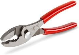
1. Slip Joint Pliers

Slip joint pliers are type of pliers which fulcrum can be easily adjustable to alter the width of the jaw. Hence, Because of the movable fulcrum, the jaws’ size range can be easily increased.

Slip joint pliers ( Types of pliers )

These pliers have a flat and serrated tip. The jaws of the pliers are curved out just below the tip for gripping rounded surfaces such as pipes. Slip joint pliers are found in almost every toolbox.

Uses :- It is used to crimp metal, loop wire, and cut soft nails. Slip-joint pliers can also be used to loosen and tighten nuts and bolts.But not used for cutting the wire.

This is also known or called as Water pump pliers.

The bolt of the fulcrum has a variety of marks to slip into when the jaws are open, allowing you to lock to a specific width. They’re commonly used in plumbing applications and can perform a variety of tasks, similar to a wrench.

2. Hose Clamp Plier

A hose clamp plier are designed to tighten the connection by compressing the hose and spring clamp.

It comes in Variety of designs. The most common type  has a peg-shaped tooth in each jaw that pinches the clamp. Some models can also be used on the hose directly.

This pliers are also known as Radiator hose pliers and Spring clamp pliers.

Uses :- For compressing the hose and spring clamp ,making the joint tight.

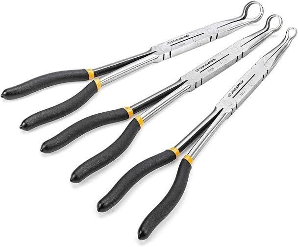
3. Round/long Nose Plier

This pliers are designed tapered in length and conical.And this has not cutting edge.

Uses :- Needle nose pliers are extremely versatile, and can be used for a variety of tasks including electrical work (radio and TV job ), jewelry making, wire bending and twisting, and fishing.

They are of the long shaper type, and thus are also known as long-nose pliers. Because of their long shape, needle nose pliers can be used in smaller areas that other types of pliers cannot reach.

It is also known as pointy-nose or snipe-nose pliers.

4. Crimping Plier

A crumpling plier tool are designed in such a way which includes Fulcrum at the end which is used As a nutcracker.

To cut the fire, first Fed the wire into the jaw jack and then to the connector.

This tool are known as Crimping tools.


Uses :-

  • Copper and aluminum wire should be cut.
  • Forged carbon steel construction for strength and durability.
  • Design of a comfortable high-leverage handle.
  • The ability to accept both insulated and uninsulated power wire terminals.
  • A thin nose enables cutting in confined spaces.

5. Diagonal Plier

Diagonal pliers are designed in such a way whose jaw have angled edge that is used to cut the wire. They are extremely strong and can also be used to cut nails.

As a result, they are useful in carpentry and electrical work.

Doagonal pliers are known by many names like diagonal cutters, diagonal cutting pliers, side-cutting pliers, etc.

The main functions of this tool is to cut any types of wire.

The diagonal plier’s function is similar to that of a simple scissor. They do, however, perform the cutting action differently. They cut the wire by indenting it and then wedging it.

When diagonal pliers are seen from the front, they form a “X” shape. Tempered steel is used to make these pliers. They go through the inductive heating process first, followed by the quenching process.
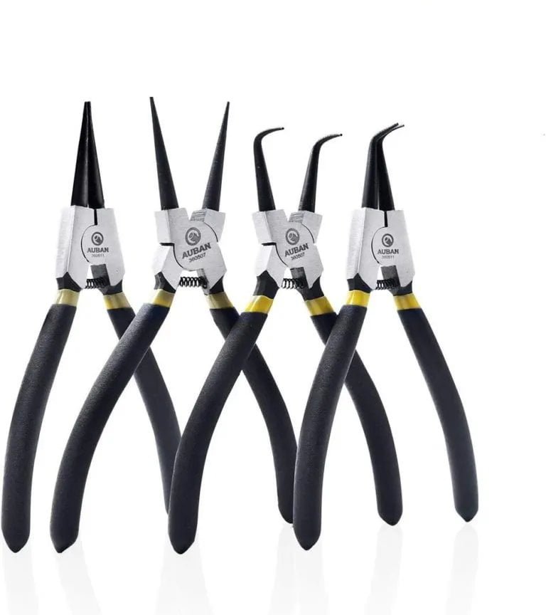
6. Snap Ring Pliers

These pliers have small, round jaws that help close the snap ring. These rings are open-ended loops that fit into the grooves of a dowel or other round object. When closed, the ring can rotate freely but cannot slide sideways. They are commonly used for gear on mountain bikes and other similar vehicles.

This pliers are commonly known as Circlip pliers or c-clip pliers. Often times they are named as lock ring pliers. Frequently, Often times it is named as lock ring pliers.

Applications of snap ring pliers :-

  • This pliers are used to insert As well as remove the snap ring.
  • Hikers use snap ring pliers for a variety of purposes.

7. Tongue And Groove Pliers :


Tongue and groove pliers are an adjustable type of pliers with a toothed groove along the upper handle, that allows the lower jaw to be locked into a number of positions. Because of the angled jaws, this tool is great for turning nuts and bolts.

Design

The Tongue and groove pliers have a simple design. Tongue and groove pliers have jaws that are set 45 to 60 degrees from the handles.

The lower jaws of the Tongue and groove pliers can be moved to a variety of positions depending on the application. These pliers are designed so that they can be adjusted to a variety of sizes without increasing the distance between the two handles.

Applications

  • For turning and holding nuts and bolts, tongue and groove pliers are used.
  • They are commonly used for gripping irregularly shaped objects and, sometimes, for material crimping.
  • The Tongue and groove pliers’ design allows us to use them in applications where space is limited or a very small area is present.
  • Their handles are extremely long in order to provide more leverage. Tongue and groove pliers have handles that range in size from 9.5 to 12 inches.

Because of their larger handles, these pliers are easily identified.It is also known as channel lock.

B) According to Special Types of Plier

1. Battery Pliers

Battery pliers are designed to used mainly in the automotive industry for maintaining bolts on car batteries and jumper cables. These pliers are  made up of small angled jaws. The lower jaw is slightly shorter, and both jaws are thicker to make them more durable.

Uses of battery pliers :-

  • Battery pliers are used in the automobile industry to maintain the bolts on the battery.
  • It used for both top-post and side-post battery terminals.
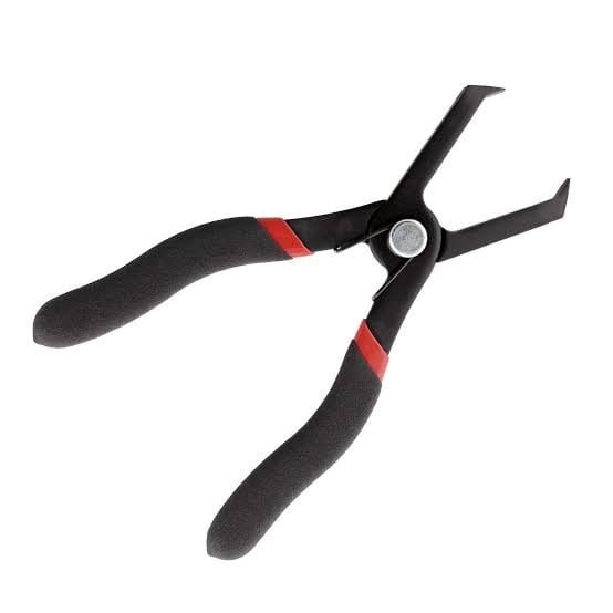
2. Bent Nose Pliers

Bent nose pliers are consists of a set of jaws that bent at some angle at the midpoint ( generally 45 or 90 degree ).

The function of bent nose pliers is similar to that of needle-nose pliers; the only difference is that they have a bent nose.

By looking at their curved beak, we can easily identify bent nose pliers.

Bent nose allow them to Hold any surfaces when multiple Pliers are required or In the fase when It is very dificult to Reach an angle with Normal needle nose pliers.

Applications :-It is useful in jewelry making, electrical work, and other industries that deal with shaping wire.

3. Bail Making Pliers

The bail making pliers‘ jaws are made up of two cylindrical rods. Here, One rod is slightly larger than the other.

By looking at the jaws of the bail making pliers, we can quickly identify them. The pliers with the jaws that resemble cylindrical rods are the bail making pliers.

Uses of bail making pliers are :-

  • Bail making pliers are used to make delicate items such as jewelry and other valuables things.
  • They’re also used in the production of clasps and ear wires ,And many other shaped loop components.

4. Nail Puller Pliers

These pliers are specifically designed for pulling nails, as the name implies. Nail puller pliers resemble tongs in appearance, but their jaws are tapered.

These tapered jaws assist them in extracting the nails from the wood. The forged steel dominates the head of these pliers.

Uses of this pliers are following :-

To remove the staples, use nail puller pliers.

This type of plier is used by carpenters and people interested in woodworking.

5. Brake Spring Pliers

This is type of pliers used by mechanics to to handle the spring Which are inside the drum brakes.

It has two jaws and the jaws are very unique in shape.

One jaw is rounded, while the other is curved in shape. One jaw is used to remove the spring, while the other is used to insert it.

Uses of brake spring pliers are :-

Brake spring pliers are mainly used in the automotive industry.

They can also be used in applications involving the removal and insertion of springs.

6. Canvas Pliers

This is a type of pliers which has rectangular stripes on the jaw which is used to hold the wires.

The canvas players are made of chrome-plated steel. Teeth that are completely mated ensure a firm, non-slip grip. The handle has a built-in spring return that opens the pliers when you release.

They are also known as canvas stretching pliers.

Anyone can easily identify this pliers by Looking the jaw of pliers .There is a rectangular Strips on their jaws which is used To hold the wires.

Uses of Canvas pliers are :-

  • It can be used to remove the Insulation of electric wire.
  • It is used to hold the wire Or small rectangular Shaper long wire Type objects.

7. Chain Nose Pliers

Featuring the stubby triangular Jaw, The chain nose pliers, are one of many tools used in wire shaping and jewelry making. The jaw’s design allows the wire to bend, fold, and shape itself.

When working with beads, the tip aids in closing and opening the bead tips and jump ring.

8. Flat or Combined Pliers

This is a multi-purpose device.

The jaws of these multi-purpose devices are divided into three distinct segments. The first parts from the tip are serrated gripping surfaces. A round serrated section behind it makes it easier to grip tubes and other thick round objects.

Finally, there is a cutting surface in the proximal part of the base. The latter, which lacks a round center segment in the jaw, is frequently mistaken for linesman’s pliers.

Uses of flat or combined pliers are :-

  • Combination pliers used to cut, grip, twist, and bend.
  • Their jaws have a rough surface that works well for removing wire insulation.

Note :- This pliers should not be used to cut a very hard metal because the edge will be ruined. Parallel slots on the inner side of its jaws are made for a firm grip on jobs.

9. Eyelet Pliers

Eyelet pliers are a type of plier that is primarily used in the clothing industry. Its primary function is to incorporate laces and drawstrings into the cloth.

These eyelets have a ring and an elongated hub that must be crimped down.

Most modern eyelet pliers have interchangeable dies that allow for both hole punching and crimping, though some only have crimping surfaces or an upper jaw wheel with various die tips.

Uses of Eyelet pliers are :-

  • In the clothing industry, eyelet pliers can be used to punch holes.
  • The eyelet pliers are used to make the button hole on both the shirts and the jackets.

10. Fencing Pliers

When viewed from above, this  multi-tool looking resembles a hammer with two handles. Notches in the fulcrum allow you to cut wires of various gauges, and the side of the left jaw has a hammer surface for driving in staples.

The claw of the right jaw can be used to remove staples, and the jaws themselves have a gripping surface and a rounded grip hole.

11. Grommet Pliers

Grommet pliers perform the same function as eyelet pliers, but they look different.

A distinctive structure can be found in the grommet pliers’ jaws. You can get a good idea of what the Grommet pliers are by looking at the image below.

Uses of Grommet pliers :-

  • Grommet pliers have a wider range of uses than eyelet pliers
  • The grommet pliers, to be more precise, can be used for complex and heavy applications.
  • They are also used in the construction of tents.
  • Grommet pliers are frequently used to make holes in hard materials.

12. Hose Grip Pliers

These specialized type of pliers are designed to easily carry small hoses into and out of tight spaces. Their grabber jaws are shaped to protect hoses such as vacuum lines, heater hoses, and fuel lines.

Simply hold the hose and turn or turn. Hose grip pliers are also useful for hose clamps, spark plugs, and a variety of other small components.

They are popularly known as the grabber pliers.

They have grabber jaws. Hose refers to pipes or tubing. The best way to recognize them is to look at their grabber jaw, which has a very distinct shape.

Uses of the hose grip pliers :-

  • Plumbers use hose grip pliers in a variety of plumbing applications.
  • Hose grip pliers are also ideal for clamps, spark plugs, and other small components.

13. Linesman Pliers

Lineman’s pliers are mostly used by linemen, that’s why they have such a name. Lineman’s pliers are primarily used for twisting, bending, and cutting wire.

Do you know how to recognize the lineman’s pliers?

Lineman’s pliers are distinguished by the flat gripping surface on their snub nose. So, if you come across a plier with a gripping surface on the snub nose, it’s the lineman’s pliers.

The Lineman’s pliers also have a beveled cutting edge, which is an important feature.

Lineman’s pliers are used in heavy-duty applications and are machined from forged steel. The rivet is used to control the accuracy of this plier type. Even when used in applications requiring greater force, the rivet prevents the pliers from breaking or being damaged.

Lineman’s pliers have two grips. These two grips allow you to easily handle them. These grips have an insulation layer on them. When working with electric wires, this insulation protects the users from electric shocks.

Some models of these pliers are designed to withstand higher voltages of up to 1000V.

Uses of linesman pliers :-

  • Lineman’s pliers are most commonly found in electrical applications. They are employed in the bending, cutting, and straightening of wire.
  • They are also used to strip wire from time to time. However, for the same applications, they are less efficient than a wire stripper.
  • They are frequently used to pull the fish tape a few times.
  • A few lineman’s pliers include a crimping tool, which is then used to compress the crimped connections.
  • The square nose of the lineman’s pliers produces perfect right-angle bends.
  • They can also be used to cut drywall and steel screws.
  • The lineman’s pliers’ tapered nose can be used to ream the rough edge.
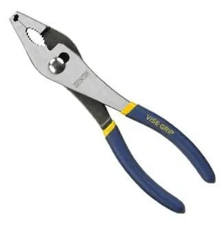
14. Locking Pliers

These pliers are designed to lock the jaws in place, making them useful for snatching screws and bolts.

An over-center toggle action is used in the locking pliers to lock into a specific position. The locking pliers have various uses in the manufacturing and design industries.

They are a very specific type of pliers that are sometimes referred to as Vise-Grips. William Petersen invented the first locking plier in the United States in 1924. Thomas Coughtrie invented Mole wrenches after the second type of locking pliers.

The mechanism involved in the locking pliers

The locking pliers are made up of two jaws. The bolt for adjusting the space between the jaws is housed in one of the handles. The lever for unlocking the pliers is located on the opposite side of the handle. The locking pliers are sold under the brand names Vise Grips and Mole.

In everyday life, mechanics in the United States refer to locking pliers as Vise-Grips, while mechanics in the United Kingdom refer to locking pliers as Mole Grips.

The bolt is used to tighten or loosen the jaws. They are kept in such a way that they are smaller than the object to be gripped.

The jaws are now fixed on the gripped object.

Advantages of locking pliers are

  • They can be used to generate more force because their lever action is far stronger than that of other types of pliers.
  • With the locking pliers, you can easily apply a controlled force.
  • The locking pairs can remain close without the need for human intervention.
  • Locking Pliers are useful for a variety of tasks.

Uses of locking pliers are :-

  • In the case of holding metal parts, a very common application of locking pliers is found.
  • You may have come across applications where we needed to hold pipe without squeezing it.Locking pliers are essential in such applications.
  • Locking pliers are also used to secure the rounded nut or bolt.

15. Piston Rings Pliers

Piston ring pliers are used to remove engine piston rings. There are two kinds of piston ring pliers. Cast iron is used to make these pliers. The curved tip of the piston ring pliers distinguishes it and allows us to easily identify it.

Uses of piston rings pliers are :-

  • Piston ring pliers are used in the automotive and engine industries, as well as in other fields where engines are present.
  • They are also sometimes used to provide a seal between the piston and the cylinder wall.

16. Running Pliers

This pliers make a clean break along the run lines in the glass. The wide jaws are adjusted to match the thickness of your glass and have a centerline to ensure precise alignment when moving with the score. They are used to make stained glass crafts.

17. Sheet Metal Pliers

Sheet metal pliers, as the name suggests, are used in industries that work with sheet metal. The jaws of these pliers are wide and rectangular.

These types of pliers are identified by their rectangular unique jaws. The  jaws  of sheet metal plier scan be used to bend sheet metal and for the formation of seams.

18. Spark Plug Pliers

These pliers have insulated tongs or a cylindrical holder attached to their narrow jaws.

As the name suggests, the tips hold the spark plugs by boot or plug wires, assisting in automotive repair.

The jaws of welding pliers are similar to those of combination pliers, with the needle having the same tip as the jaw of the nose plier.

Uses :- They are capable of a wide range of tasks, including splatter removal, wire gripping, cutting, and hammer handling. As the name implies, these pliers are commonly used in welding-related trades.

20. Split Ring Pliers

The split ring pliers have a bent tip on its lower jaw. This nozzle acts as a wedge, splitting individual coiled rings. They are used in the production of fishing tackle and keyrings.

This pliers are  also known as fishing pliers.

21. Oil Filter Pliers

Oil filter pliers are a special type of plier that can only be used in a specific industry. Their jaws are toothed and formed into a C shape.

To get a better idea of the oil filter jaws, look at the image below.

Uses of oil filter pliers :-

  • In the automobile industry, oil filter pliers are used.
  • Second, they’re employed in the removal of oil filter casings.


22. Soft Jaw Pliers

Many different types of pliers are included in the soft jaw pliers. The difference is that these pliers have padded jaws to prevent scratches on chrome and other soft metals or exposed surfaces.

Uses :- They are primarily used for plumbing and scuba diving equipment.

23. Gas Pliers

These pliers are used to open nuts on gas and oil pipes, among other things. Like slip joint pliers, it has an opening that can be enlarged or closed as needed.

Precautions of using Gas pliers

This Pliers should never be used in place of  a hammer, spanner, or wrench.

Different pliers should be used for different jobs.

24. Push Pin Pliers

Push Pin Pliers are used to remove plastic push pins. It protects the anchors and pins from damage. The jaws of the push pin pliers are wedge-shaped to help remove the anchors more effectively.

The wedge-shaped jaws of such pliers make them easily identifiable. Because of the available springs, they provide us with more comfort.

Uses of push pin pliers are :

  • Push pin pliers are used in automotive work.
  • They are also used in processes where pin-style anchors are commonly used.

25. Wire Twisting Pliers

The jaws of wire twisting pliers are very short. It has two jaws and both of the jaws have a cutting edge.

A knob and a special cylindrical locking mechanism are located between the two handles of the wire twisting pliers.

By paying attention to the above description, we can easily identify the wire twisting pliers.

With the help of this locking mechanism, the entire wire spins and we get the required twisting. With the help of the wire twisting pliers, we can twist many wires at the same time. We can twist multiple wires at the same time using wire twisting pliers.

Uses of wire twisting pliers :-

  • Wire twisting pliers are used by electricians as well as in the electronics industry.
  • Sometimes, Such pliers are also used by jewelers

With this article we have tried to incorporate all the types of pliers that are being used in the various Industries along with their images for proper understanding and visualization. the Pliers images will help you to remember and understand the various types of pliers accordingly. If you liked this article please share it with your friends.

Check Out Other Important Topics

IC Engine

Electrical

Important PDFs

Boilers

Synergy Maritime Exam

Naval Arch

Interview Questions

Difference Between

Types of Pumps

Types of Valves

MEO Class 4

Auxiliary Machines

Home

Ballasting and deballasting of ship

Ballasting of ship is a process by which sea water is taken on ship in a dedicated ballast water tank while cargo is discharging.

Ballasting of ship

Deballasting is a process by which sea water is carried out in sea from ballast tank when the ship loading cargo.

Deballasting of ship

Simply,Ballasting or de ballasting is a process in which sea water is taken in and out from the ship for its stability when it at port or  at the sea.

The sea water which is carried by a ship is called as ballast water.

Ballasting and deballasting of ship

What is the purpose of ballasting ?

The main purpose of ballasting a vessel for a voyage are to increase its manageability (and safety), especially in rough weather; control its draft and trim for maximum efficiency; and control its stability to ensure safe passage.

Must read :- Centrifugal pump

When ballasting or Deballasting required ?

It is required when the ship is
1.During Loading or unloading of cargo
2.to enter a channel
3.cross any canal like panama canal and Suez canal and
4 when ship is going for berthing.

Why sea water is used for ballasting ?

For ballasting vessel ,ballast water is sea water carried by a vessel in its ballast tanks to maintain the vessel’s trim, stability, and structural integrity. Ballast tanks on ships are outfitted with a piping system and high-capacity ballast pumps to carry out the operation.

As we know that for stability of ship, ballasting is done.In ancient time,Ship did the work of carrying hard weights/solid weights in form of rocks and sand bags for stability when there was minimum cargo or no cargo being carried.

However, as time passed, difficulties arose during the loading and unloading of solid cargo. Because the process of transferring solid cargo was time-consuming, solid ballast was replaced by water ballast. Because sea water was readily available in large quantities, it was used in the ballasting and de-ballasting processes.

Why is ballasting of ship done ?

Ballast water is carried on board vessels in order to maintain safe operating conditions during a specific voyage or portion of a voyage. Proper ballasting (in terms of the amount and distribution of water taken aboard) performs the following functions:

1.reduces stresses on the ship’s hull

2.ensures transverse stability

3.controls the propeller’s submergence, which aids propulsion.

4 improves maneuverability by submerging the rudder and reducing exposed hull surface (freeboard or windage)

5.compensates for the weight lost as a result of fuel and water consumption

Ballast condition, including when and how much water is loaded, determined by ship’s officees.It is determined on basis of the specific vessel’s operating needs and national and international requirements for proper vessel trim and stability at sea.

Ballast conditions at sea

The main purpose  of ballasting a vessel for a voyage are to increase its manageability (and safety), especially in rough weather; control its draft and trim for maximum efficiency; and control its stability to ensure safe passage. The following list summarizes the factors that influence ballast conditions at sea.

Heavy weather conditions

Ships must be anchored deep enough in the water to ensure safe passage, especially in bad weather. If the bow of the ship is not deep enough, the ship’s forefoot will emerge from the water surface on a regular basis. This causes hull slamming (or heavy impact) when the bow hits the water with high velocity on re-entry.

Sailing with full tanks

Depending on the ship’s stability and strength requirements, ballast tanks used to control trim or heel, some fuel oil tanks, and tanks containing fresh water for domestic use may be partially full at sea. It is usually necessary to sail with as many of the tanks on board as possible, either completely full or completely empty. When a tank is not completely full (i.e., “slack”) and the ship heels, the free surface effect of the liquid in the tank moves the center of gravity of the liquid in the tank, reducing the ship’s transverse stability (see Appendix C).


Furthermore, fluid in a slack tank sloshes around during ship motion, which cause excessive loads on tank/hold bulkheads, frames, or underdeck structure. This could lead to structural failure in severe weather conditions. As a result, when changing ballast at sea, the ballast in a single tank or pair of tanks should be completely changed before moving on to the next tank or tanks.

Controlling trim during voyage

The draft and trim of the ship will change as fuel is consumed during a voyage. Thousands of tons of fuel may be consumed during a long voyage. As a result, in order to keep the hull immersed correctly for maximum efficiency, additional ballast is frequently required as the voyage progresses. Some ship designs position the fuel tanks so that the ship naturally trims by the stern as the fuel oil is consumed, but ballasting may still be necessary. Ballast capacity and location on a given voyage are determined by examining the estimated amount of fuel to be consumed, the expected weather conditions, and the required draft and trim for the arrival port (s).

Transverse stability considerations

A ship’s transverse stability is defined as its ability to sail upright and avoid capsizing. To achieve proper transverse stability, the ship’s righting moment must be carefully controlled (see Appendix C). The ship should ideally be loaded and/or ballasted in such a way that it has a smooth rolling period that is neither too fast nor too slow. A ship that rolls too fast has excessive stability (a stiff ship) and has a strong tendency to quickly return to its original upright position. This causes a very uncomfortable motion that can put a lot of strain on the ship’s structure and cargo lashings, as well as a lot of sloshing in the slack tanks.

A vessel that rolls too slowly has insufficient stability (it is a tender ship) and may capsize in bad weather. When ballast is moved, it causes slack ballast tanks to form. When the vessel heels, the associated free surface effect can cause a weight shift, which has a negative impact on the ship’s transverse stability.

Ballast conditions in port

Bulk oil carriers (tankers), dry bulk carriers, and the majority of other ships deballast during cargo loading and reballast during cargo discharge (see Table 2-1). A fleet of ships operates as float-on, float-off platforms, with the ship ballasted down to allow cargo to be floated on board and deballasted to lift the cargo for the journey. For unloading, the procedure is reversed.

Controlling draft and trim for port entry

Vessel must alter draft and trim to when entering to ports ,Berths,or both at loading or unloading.
Ballast may be discharged to reduce water drafts when entering certain ports or approaching specific terminals, and it may be added to reduce air draft when clearing bridges or approaching under loading heads at some bulk cargo terminals. These operational parameters can limit the timing and location of ballasting and deballasting.

Safe longitudinal loading consideration

The distribution along the hull of the difference between the light ship weight, including cargo, fuel, ballast, and other dead weight items, and the supporting buoyancy force determines the shear forces and bending moment on a ship’s hull. Buoyancy support forces change in a seaway as waves move along the hull and the hull moves relative to the sea surface. The ship operator must ensure that the ship’s in-service conditions are consistent with the ship’s structural design.

Summary of Ballasting or Deballasting

When the ship is not carrying cargo, it becomes light in weight, which can affect its stability. As a result, ballast water is stored in dedicated tanks on board the ship to stabilize it. Ballasting is the process of filling tanks with ballast water using large capacity ballast pumps.

When the ship is loaded with cargo, the weight of the cargo itself maintains the ship’s stability, and thus no ballast water is required. De-ballasting is the process of removing ballast water from ballast tanks in order to empty them.

Check Out Other Important Topics

Home IC Engine Electrical Important PDFs Boilers Synergy Maritime Exam Naval Arch Interview Questions Difference Between Types of Pumps Types of Valves MEO Class 4 Auxiliary Machines

Source :- https://en.m.wikipedia.org/wiki/Ballast

Fuel Oil System in Ship For Marine Diesel Engine

Fuel oil system in ship For marine diesel engine are which operate on heavy fuel oils: Fuel oil transfer system, Fuel oil treatment system and Fuel oil supply system.Various piping systems for bunkering, storage, transfer, offloading, and treatment of fuel oils are provided.

Fuel Oil Transfer System

This system receives, stores, and delivers fuel to settling tanks. Fuel oils are loaded through deck fill ( bunker manifold ) connections with sample connections to allow the fuel to be sampled as it is brought aboard. HFO is stored in tanks equipped with heating coils.

HFO is transferred to the fuel oil settling tanks via FO transfer pumps equipped with a suction strainer in preparation for use. The piping is set up so that the pumps can transfer fuel from storage tanks to deck connections for offloading. Settling tanks are used to allow gross water and solids to settle to the bottom of the tank.

Fuel Oil Treatment System

Fuel oil is transferred from the settling tanks to the service tanks via the FO treatment system. The two-stage process is commonly used for cleaning heavy fuel oils (HFO). The fuel is heated to about 50-60°C in a settling tank before being drawn out by the purifier inlet pump.

The fuel is delivered by the inlet pump to a thermostatically controlled heater, which raises the fuel temperature to approximately 80°C, and then to the centrifugal purifier. The purifier discharge pump then transfers the dry purified fuel to a centrifugal clarifier. Following clarification, the clarifier discharge pump transports the fuel to the service tank for use by the engine.

Fuel Oil Supply System

The fuel from the service tank is delivered to the diesel engine via this system.
This system consist of :-
1.Fuel oil storage tank (heavy fuel oil )
2.Transfer pump
3.settling tank
4.Circulating pump on separator
5.Preheater
6.Seperator
7.Tank for purified oil
8.Shut off valves
9.Tank for purified diesel oil
10.Shut off valve
11.3-way valve
12.Flow meter
13.Mixing tank
14.Vapour trap
15.Booster pump
16.preheater
17.Filter, heatable
18.Thermometer
19.Fuel pump feed pipe
20.Fuel injection pump
21.High – pressure fuel pipe
22.Fuel injector
23.Diesel Engine
24.Fuel return pipe
25.Pressure Gaye
26.Constant Pressure Valve
27.Prewarming by -pass

Fuel oil supply for a two-stroke diesel engine

A slow-speed two-stroke diesel engine is usually configured to run continuously on heavy fuel and to have a diesel oil supply available for maneuvering purposes.

The oil in the system shown in Figure is stored in tanks with a double bottom, from which it is pumped to a settling tank and heated. After passing through centrifuges, the cleaned, heated oil is pumped to a daily service tank.

Fuel oil system in ship

To ensure constant supply of fuel to the mixing tank via the fuel oil pipes and the flowmeter,the heavy fuel oil tank should be located high enough over the mixing tank.To rule out the possibility of heavy fuel oil entering the diesel oil day tank ,the latter should be located above the heavy fuel oil tank or protected by means of a non return valve.

The oil flows from the daily service tank to a mixing tank via a three-way valve. A flow meter is installed in the system to monitor fuel consumption. Booster pumps are used to deliver oil to engine-driven fuel pumps after passing it through heaters and a viscosity regulator. The fuel pumps will deliver high-pressure fuel to the injectors.

The viscosity regulator regulates the temperature of the fuel oil in order to provide the proper viscosity for combustion. A pressure regulating valve ensures that the engine-driven pumps have a constant supply of pressure, and a pre-warming bypass is used to warm up the fuel before starting the engine.

A diesel oil daily service tank that is connected to the system via a three-way valve can be installed. The engine can be started and maneuvered using diesel oil or a combination of diesel and heavy fuel oil. The mixing tank collects recirculated oil and also serves as a buffer or reserve tank, supplying fuel when the daily service tank is empty.

In the event of problems during manoeuvring on heavy oil engines, there should be no hesitation in switching to diesel oil, regardless of whether the engines are operated via bridge control or engine room control.


Main engines designed to run on heavy fuel oil must be used in accordance with the manufacturer’s instructions. All other types of main engines must be operated on diesel oil in accordance with the manufacturer’s instructions.

Safety services fitted on fuel system on ship

The system includes several safety devices, including low-level alarms and remotely operated tank outlet valves that can be closed in the event of a fire

1.Quick closing valves on settling/service tanks
2.relief valves on 2 pumps/heaters
3.quick closing valve on mixing/vent tank
4.pipes lagged/save-alls under pumps and heaters
5.low fuel oil pressure alarm
6.high fuel oil pressure alarm
7.low fuel oil temperature alarm
8.high fuel oil temperature alarm
9.emergency remote stops for pumps
10.high pressure pipes between fuel injection pump and injector are double skinned.

Of Each Components of fuel oil system of ship

Fuel oil system on ship

1.Service tank :-Fuel is transferred to the service rank via a centrifuge from service tank.

2.Change over switch :- The switch in the engine control room or the handwheel on top of the valve can be used to operate the change over valve automatically.

It used to be common practice to switch to diesel fuel for maneuvering purposes. Modern methods of fuel oil recirculation to keep the fuel hot at the injectors have rendered this practice obsolete.

3.Quick closing valve :- Fuel is drawn from service tank through a quick closing valve. These can be closed remotely in case of emergency (e.g. fire). This can be done with simple pull wires, hydraulically, or  by compressed air.

The fuel then passes via the change over valve through a set of filters into the supply pumps.

4.Filter :-A suction filter removes any particles that could cause damage before the fuel enters the supply pumps. There are two filters, one for each of the two pumps. They are made of fine metal gauze and can be cleaned and reused as needed.

5.Pump :- The pressure is raised to about 7 bar by the supply pumps. A pressure regulating valve is used to keep the discharge pressure constant.

6.Regulating valve :-There is also a manual bypass which can be used should the regulating valve develop a fault.

7.Auto back filter :-The fuel is passed from the supply pumps to a series of backflushing filters (25 micron). The filter elements are housed in the pods. When the filters begin to clog, a differential pressure sensor triggers a backflushing routine, which allows the filters to clean themselves. Backflushing oil containing sediment from the filters drains to the fuel oil drain tank, where it can be recovered and purified.

When a mesh type filter is used, the filter can be removed from service line for cleaning.

8.Flowmeter :-

The fuel is pumped via a meter so that the quantity of fuel used can be monitored and the specific fuel consumption of the engine calculated.

In the case that the meter has to be bypassed, then the fuel is led across a pressure retaining valve.

9.Mixing column :- The fuel is then passes to a mixing column or buffer tank where it mixes with returned fuel from the main engine.

The mixing column is fitted with a relief valve and an air release (see in the fig ) and the outlets from these are led via a sight glass to the fuel oil drain tank.

10.Booster pump :- Fuel oil circulating pumps from the buffer tank pressurize the fuel to about 8 bar before it is passed to the heaters and engine.

11.Steam is used to heat the oil (although thermal oil or electric heaters are used on other systems). A viscosity measuring device regulates the temperature of the oil. The viscosity must be kept at the proper level for injection. It is set to 16 centistokes on this particular system.

12.Filter :-
After passing through the heater and before reaching the main engine inlet rail, the fuel is filtered once more to ensure that it is free of abrasive contaminants that could damage the fuel pumps, injectors, and cylinder liner.

13.Fuel oil inlet rail :-

Fuel enters each fuel pump from the main engine inlet rail (one per cylinder). The fuel pump delivers high-pressure fuel (250bar or higher) to the fuel injector (s).

14.The fuel return is the lower connection on the fuel pump. More fuel than is required is delivered to the pump. The surplus is returned to the buffer (mixing) tank.

The atomized fuel is delivered to the cylinder by the fuel injectors. When no fuel is being injected, the injectors recirculate back to the fuel return.

14.Back pressure control valve :- A backpressure control valve is installed on the return line to keep the fuel oil pressure at the required level (on this system, about 8 bar).

Check Out Other Important Topics

Home IC Engine Electrical Important PDFs Boilers Synergy Maritime Exam Naval Arch Interview Questions Difference Between Types of Pumps Types of Valves MEO Class 4 Auxiliary Machines

Refrigeration Cycle – Know All the Stages, Components & Diagrams

In this article, I am going to explain about refrigeration cycle in details like definition of Refrigeration, What are the 4 cycles of the refrigeration system? What is the principle of refrigeration? What are the parts of refrigerator? Refrigeration cycle diagram and working. Before starting first understand the term refrigeration.

What is Refrigeration ?

Refrigeration means cooling a space, substance or system to lower and/or maintain its temperature below the ambient one (while the removed heat is rejected at a higher temperature). In other words, refrigeration is artificial (human-made) cooling.

What is Refrigeration Cycle ?

Refrigeration cycle is a cycle of mechanical system in which transmission of heat flow from one place at a lower temperature (the source ) to another place at a higher temperature ( the sink or heat sink ) by continuously circulating, evaporating, and condensing a fixed supply of refrigerant in a closed system.

Refrigeration cycle is a thermodynamic cycle to generate refrigerating effect with the use of evaporator, compressor, condenser & expansion valve.

Refrigeration cycle name – It is also called heat pump cycle .

Thus, a heat pump is called as a “heater” if the objective is to warm the heat sink (as when warming the inside of a home on a cold day), or a “refrigerator” or “cooler” if the objective is to cool the heat source (as in the normal operation of a freezer).

In both cases, the working principles are same. Heat is removed from a cold place to a warm place. Below given is the refrigeration cycle diagram :

Refrigeration Cycle Diagram

Refrigeration Cycle working principle Diagram

Vapour Compression Cycle

Vapour Compression Refrigeration system is the most widely used refrigeration system.

Vapour compression refrigeration cycle is a process that uses the physics of phase change heat transfer and the unique properties of a refrigerant to transfer heat from a relatively cold source to a hot medium.

What is the Basic Refrigeration Cycle ?

The basic components of any refrigeration system working on the vapour compression cycle are the compressor, condenser, expansion valve and evaporator and the refrigerant fluid which is alternatively vaporized and liquefied during the refrigeration cycle.

The temperature at which a fluid boils or condenses is known as the saturation temperature .

Components of Refrigeration Cycle

The 4 main Components of Refrigeration cycle

1. Compressor
2. Condenser
3. Expansion valve
4. Evaporator

Refrigeration Cycle Working

Working of vapour compression refrigeration system has been explained step by step including the work done by each component in the cycle and can be seen in the refrigeration cycle diagram also.

1. Compressor

The compressor in a vapor compression cycle helps in raising the pressure of the vaporizer refrigerant, causing its saturation temperature to rise, so that it is higher than that of the the sea water or air, cooling the condenser. The compressor also promotes circulation of refrigerant by pumping it around the system.

Note :- Refrigerant enters the compressor as low-pressure, low-temperature gas, and leaves the compressor as a high-pressure, high-temperature gas.

Why compression takes place :- Compression takes place to raise the saturation temperature and refrigerant pressure.

2. Condenser

In the condenser of the vapour compression system the refrigerant is liquefied by being subcooled to below the saturation temperature relating to the compressor delivery pressure, by the circulating sea water or air for domestic refrigerator.

Latent heat, originally from the evaporator, is then transferred to the cooling medium. The liquid refrigerant, still at the pressure produced by the compressor, passes to the receiver and then to the expansion valve.

Note :- After condensing, the refrigerant is a high-pressure, low-temperature liquid, at the point it’s routed to the loop’s expansion device.

What happens in condenser :- Heat is transferred from the refrigerant to a flow of water

3. Expansion valve

The expansion valve is the regulator through which the refrigerant flow from the high pressure side of the system to the low pressure side. Its throttling effect dictates the  compressor delivery pressure which must be sufficient to give the refrigerant a saturation temperature which is higher than the temperature of the cooling medium.

The pressure drop through the regulator causes the saturation  temperature of the refrigerant to fall so that it boils at low temperature of the evaporator. In fact, as the liquid passes through the expansion valve, the pressure drop makes its saturation  temperature fall below its actual temperature.

Some of the liquid boils off at the  expansion valve taking latent heat from the remainder and causing it’s  temperature to drop.

The expansion valve throttles the liquid refrigerant and maintains the pressure difference between the condenser and evaporator, while supplying refrigerant to the evaporator at the correct rate. It is thermostatically controlled in modern systems.

What happens to refrigerant in Expansion valve :- When the refrigerant enters the throttling valve, it expands and releases pressure. Consequently, the temperature drops at this stage.

4. Evaporator

The refrigerant entering the evaporator coil at a temperature lower than that of the surrounding. Secondary coolant (air or brine ) receives latent heat and evaporates. Later the heat is given off in the condenser, where the refrigerant is again compressed and liquefied.

Note :- Refrigerant enters the evaporator as a low temperature liquid at low pressure, and a fan forces air across the evaporator’s fins, cooling the air by absorbing the heat from the spaces.

What happens to refrigerant in evaporator :- It evaporates and absorbs latent heat of vaporization.

For a small refrigerator the evaporator cools without forced circulation of secondary coolant. In larger installation, the evaporator cools air or brine which are circulated as secondary refrigerants.

Frequently Asked Questions

What is the refrigeration cycle called?

Refrigeration cycle is also called heat pump cycle

What are the 4 cycles to the refrigeration system?

The 4 main Components of Refrigeration cycle are :
1. Compressor
2. Condenser
3. Expansion valve
4. Evaporator

What Are the Different Types of Refrigeration Systems?

There are four main refrigeration cycle types :
1. Mechanical Compression Refrigeration System
2. Absorption Refrigeration
3. Evaporative Cooling
4. Thermoelectric Refrigeration

Which gas is used in refrigerator?

Tetrafluoroethane:

HFC-134a (1,1,1,2-Tetrafluoroethane) is one of the commonly used refrigerant gases which you can find in almost all the present time refrigerators.

we have covered all the required details of Refrigeration cycle ( vapour compression refrigeration system, vapour compression cycle, heat pump cycles ). This is the most basic refrigeration cycle and is known by many different names as mentioned. We got refrigeration cycle explained with the help of refrigeration cycle diagram and learned the thermodynamics of refrigeration.

For Better Explanation

Refrigeration Cycle Explained on YouTube

Check Out Other Important Topics

IC EngineImportant PDFsBoilersSynergy Maritime ExamNaval ArchMEO Class 4
Interview QuestionsDifference BetweenTypes of PumpsAuxiliary MachinesTypes of ValvesHome

Piston cooling in 2 stroke marine Diesel Engine

In this article I am going to explain piston cooling in 2 stroke marine diesel in details.

Cooling of piston is done to to prevent stresses in the piston crown due to temperatures induced by combustion.

Piston cooling in 2 stroke marine diesel engine (The maine engine piston cooling ) is done by one of the cooling medium –

1. Water and

2.oil

Note :- Water-cooled pistons were mainly used in old MAN engines and Sulzer RND ,RLA and RLB engines.

Nowadays both MAN B & W and Sulzer engines prefer oil cooling to conventional water cooling piston.

Why Oil Cooling is preferred to conventional water cooling piston ?

Ans :- as the former reduces the risk of lube oil contamination in case of leakage.

Difference in piston cooling of sulzer and B & W Engines

In Wartsila engine , an articulated or swinging arm is attached to the crosshead which supplies the inlet oil.

In B&W Engines Telescopic pipe is used for supplying oil to the crosshead which supplies oil to the inlet pipe of piston rod.

MAN B & W

A branch of lube oil goes to crosshead.In MAN engine the lube oil is connected to inlet in the crosshead using a telescopic pipe,it moves up and down along with the crosshead and oil is supplied to it from the top .

Figure showing oil from telescopic pipe branching for piston cooling
Animations of crosshead and telescopic pipe

Once the oil reaches the engine inlet it does three functions

A.Some oil travel up the piston rod to cool the piston and then comes down.

B.Some oil lubricates the crosshead bearing and the shoe guides.

C.the remaining oil passes through a hole drilled in the connecting rod to the bottom end bearings.

And finally all oil comes to the sump.

How oil branching taking place

For understanding, How oil passes through piston rod to piston see the below figure :-

There is 3 hole showing in bottom of piston rod ( This bottom will sit on crosshead ) for flow of oil.One is in centre and other 2 is in the side.

Actually,The piston rod is utilised to carry the oil to and from the piston.The rod is hollow, and has a tube running up its centre. This gives an annular space which, with the central bore, allows a supply and return. 

Flow pattern of oil

The cooling oil is delivered to the piston crown, through the centre of the hollow piston rod, circulating through the cooling channels in the crown. The oil returns through the piston rod via small holes drilled into the piston rod where it is collected in a tray at the cross head bearing. here the oil temperature and viscosity is monitored before spilling over the tray; cascading down into the main lube-oil sump.

MAN B&W Piston:

The new MAN engine uses simple bore cooling piston and jet nozzels, which comprises of oil passage within the piston crown for uniform cooling. The MAN engine also uses a top layer thermal coating over the crown, known as INCONEL 625 coat, which is 8mm thick and protects the crown surface from overheating.

Sulzer Engine

The oil in sulzer engine provided through articulate pipe.Two pipe is provided in articulate pipe.

One pipe go for crosshead lubrication (and after xhead it goes for bottom end bearing lubrication ) and second pipe for piston cooling.

Actually,The rod is hollow, and has a tube running up its centre. This gives an annular space which, with the central bore, allows a supply and return. 

There is 3 hole showing  in bottom of  piston rod ( This bottom will sit on crosshead ) for flow of oil.One is in centre for return oil and other 2 is in the side for cooling piston.

Flow pattern of oil coolant

The Cooling oil Is delivered to the piston crown in sulzer engine is through the two outside holes in the piston rod.The larger bore being used for return oil after cooling.

This allows oil delivery at a higher pressure to the nozzles; causing it be injected as a mist against the inside surfaces of the crown and providing a more efficient cooling system.

SULZER Piston:

The new SULZER piston with concave crown comes with Jet-Shaker cooling design, wherein the jet nozzles are attached to the cooling passage of piston rod.

The piston crown design which comprises of bores and nozzles ( for supplying cooling oil with high pressure), provides better uniform cooling and reduces crown thickness and overall piston weight. This is known as jet shaker method as during downward movement of piston, the nozzle sprays the oil jet inside the bore and when the piston moves upward, the oil inside the piston crown shakes for efficient cooling.

Water Cooled Piston of Marine Diesel Engine

The diagrammatic sketch shows the general arangement for the main engine piston cooling
water system for Sulzer RD type engines.

Note:-This is line diagram of sulzer RD types engine in which one figure cooler is between sight glass and tank and in other figure cooler is after pump.I have also seen cooler is after pump in sulzer RLA and RLB engines.

The piston cooling water tank is located at lower level to allow the return cooling water to flow easily into the tank. A piston cooling pump draws the water from the tank and pumps it through the cooler into the piston through telescopic pipe arrangement.

The cooling water returns via a second telescopic pipe to the tank. Each return line has a thermometer, a flow sensor with ‘no flow’ alarm and a sight glass to observe the flow of water.


A connection is provided in the piston cooling tank as shown for the replenishment of water
as and when necessary.

A centrifugal pump supplies the cooling water under pressure to the piston crown; where it is circulated through water channels that have been cast into the piston crown.

These channels are positioned close to the walls and top of the crown, also behind the piston ring grooves to promote optimum cooling of the surfaces of the crown subjected to the high temperatures of combustion.

The water enters and leaves the piston through telescopic pipes that slide up and down on stand pipes as the piston reciprocates. These pipes have rubber water seals between them to prevent leakage of cooling medium into the crankcase lube-oil. There can also be enclosures around the seals that incorporate tell-tale leak pipes that eject water if a seal begins to leak. The pipes are located at convenient locations outside the engine enclosure, usually at control platform level.

The water temperature is maintained by a dedicated seawater cooler, and a header tank allows the system water and additive to be topped up.

Advancement of piston chamber

In water cooled piston,ribs is removed and made a bore inside which provide jet cooling.

Check Out Other Important Topics

Home IC Engine Electrical Important PDFs Boilers Synergy Maritime Exam Naval Arch Interview Questions Difference Between Types of Pumps Types of Valves MEO Class 4 Auxiliary Machines

Bulwark on a Ship: Definition, Height, Constructions

Bulwark on a Ship

Bulwark on a ship

What is a Bulwark on a Ship ? Bulwark Definition

Bulwark on a ship is a nautical term for a ship’s side to be extended above the level of a weather deck.

Define Bulwark

It is a Vertical Fore-and-aft plating just above the upper edge of the side of the ship surrounding the exposed deck(s).

Bulwark ship meaning : It is defined as boundary designed on the ship’s side to prevent passengers and crew from falling to sea.

As protection for crew and passengers, bulwarks fitted on weather decks and it is not intended as a major structural function.

Bulwark Definition : In simple sentence, bulwark meaning , a solid wall like structure fitted on the ship’s side above the upper deck to protect crew member falling into the sea.

As we know that it is fitted only to save falling crew and not intended as major structure so, they are of light scantling. The high stresses connected to adjacent structure is avoided.

Also read :- Difference between 2 stroke and 4 stroke engine

Freeing ports

Freeing ports are the opening provided on the ship side to allow the free passing of water on the deck to the sea freely.

Or,

It is an Opening or hole in the bulwarks at the level of the deck to drain water from the deck.

Bulwark on a ship

As we see the figure of Bulwark ,it is open.

Why it is open ?

The opening is called freeing ports.

Freeing ports are cut into bulwarks forming wells on decks so that the water can drain quickly.

Freeing ports area on each side depend on the length of well deck.

The ports’ lower edge must be as close to the deck as possible. It is appropriate to fit bars spaced about 230 mm apart across the port. Where hinge flaps are fitted and these hinges should be non-corrodible.

Structure of the Bulwark on a ship

What is the height of Bulwark ?

The height of Bulwark is at least 1 metre high on the exposed freeboard and the superstructure deck.

However, a reduced height may be allowed if this interferes with the operation of the ship.

Range of height

In open position,the height should be 1 metre high.These are supported by stanchions.

In some ships,these must not be more than 1.2 metres apart for forward 7 percent (%) of the length of the ships otherwise,it not be more than 1.83 metres.

Construction of the Bulwark on a ship

Bulwark should not be welded to the sheer strake to the half length amidship as this is liable to cause the plating to crack.

This can be done by riveting the bulwark to the sheer strake or by using FLOATING BULWARK, which has the advantages that the space/gap between it and the edge of the deck serve as a freeing port.

It is normally founded in a rounded sheer strake.

More photos

1.

Bulwark of ship

2.

Bulwark on a ship

So with this article we understand bulwark meaning along with more than one bulwark definition. Bulwark on a ship is very important from safety point of view.

What is camber of a ship?

In naval architecture, camber is a measure of lateral main deck curvature. The curve is applied transversely to a deck and is measured as the height of the deck at the centerline above the height of the deck at the side.

What is a girder on a ship?

A girder is a longitudinal member used in the construction of a ship’s bottom. They can be solid or hollow, and they can be placed above the keel (centre girder) or equally spaced from it (side girders). They can be continuous or divided into sections by floor sections (intercostal side girders).

What is ship gangway?

A gangway is a narrow walkway or platform that allows people to safely board a ship, truck, or train. Gangways are typically used for two purposes: allowing people and/or cargo to travel to and from docks, moored marine vessels, or aircraft, or for maintenance and loading/unloading of land-based trucks and trains.

What is the function of bulwark?

It is defined as boundary designed on the ship’s side to prevent passengers and crew from falling to sea. As protection for crew and passengers, bulwarks fitted on weather decks and it is not intended as a major structural function.

Where is bulwark located?

The Bulwark, located on the border of Tirisfal Glades and the Western Plaguelands, is the Forsaken’s last line of defence against the forces of the Scourge to the east.

What is ship keel?

The main structural member and backbone of a ship or boat, running longitudinally along the bottom of the hull from stem to stern in shipbuilding. It could be made of wood, metal, or another strong and stiff material.

What is camber and sheer?

Camber:-The deck’s transverse curvature from the centerline to the sides. This camber is used on exposed decks to direct water to the ship’s sides.
Sheer: The fore and aft curvature of the deck, rising from midship to the maximum at the ends.

What is strake in ship?

A strake is a longitudinal course of planking or plating on a vessel’s hull that runs from the boat’s stempost (at the bows) to the sternpost or transom (at the rear). The garboard strakes are the two on each side immediately adjacent to the keel.

Follow me on Twitter

Check Out Other Important Topics

IC EngineImportant PDFsBoilersSynergy Maritime ExamNaval ArchMEO Class 4
Interview QuestionsDifference BetweenTypes of PumpsAuxiliary MachinesTypes of ValvesHome