In this article you will learn about What is process planning ? What are the requirements for this process, What are the process planning steps, types, advantages, disadvantages and the sequence of activities included. Let’s start with the Definition.
What is Process Planning ?
Process planning is the procedure used to develop a detailed list of manufacturing operations required for the production of a part or a product. It is the linkage between product design and product manufacturing.
Process planning establishes an efficient sequence of operations, select proper equipment and tooling, and specifies their operations in such a manner that the product will meet all requirements stipulated in the specification. At the same time, the process will be performed at minimum cost and maximum productivity.
Basically there are two ways process plans can be generated. They are :
1. Manual Process Planning and 2. Computer Aided Processes Planning
REQUIREMENTS FOR PROCESS PLANNING
A reasonably good process plan must satisfy the following requirements:
1. A brief description of the job to be manufactured which clearly and comprehensively defines its service function.
2. Specifications and standards that stipulate the service function.
3. Working drawings of the job with complete specification.
4. Drawing of the blank.
5. Data on the quantity of parts to be manufactured in a period. spare parts required for each unit.
6. Total quantity of parts to be manufactured in a period.
7. Equipment data that includes specifications and capacity data of machine tools, and other available equipment, the data concerning the arrangement and loading of equipment in the shop.
8. Conditions under which production engineering and manufacturing are to be organized and accomplished, i.e., whether a new or existing plants, available equipment in the plant, possibility of obtaining new equipment, etc.
9. Location of the plant.
10. Availability of manpower to staff the plant.
11. Date of starting the work and date of delivery.
After having understanding of the basic requirements, the next thing is different steps in process planning.
Process Planning Steps
The purpose of process planning is to determine and describe the best process needed to produce a part. In order to accomplish these objectives, the following Process Planning Steps may be followed :
1. To become acquainted with the service function of the part.
2. To study and critically analyse the manufacturing specifications and various standards, e.g., accuracy, output, efficiency, etc., that define the service function.
3. To become acquainted with the annual output of the product.
4. To study and critically analyse the working drawings to see whether it is feasible in all respect to produce the part, and to reveal and correct any mistakes in the drawings.
5. To determine what parts to be manufactured and what parts to he purchased with their complete identification and required quantity.
6. To prepare a list of raw materials of right quality and quantity to be purchased from outside giving their shape, size and special property.
7. To select the most economical process for obtaining the blanks, and to determine the quantities to be produced for the purpose of costing.
8. To determine the most economical process for manufacturing the parts keeping in view the current production commitments, delivery date, quantity to be produced, and the quality standard.
9. To determine the best sequence of operation to be performed on each part in a particular process.
10. To select the machine tools that will perform the operations with required accuracies.
11. To select any other accessories and equipment like jigs, fixtures, dies, gauges, etc., that may be required to give higher production rate.
12. To lay out the equipment and workplaces, calculate machine loads and make necessary corrections in the process.
13. To revise the process to correct all mistakes and shortcomings that were discovered when the process was realized in actual production.
14. To determine the stages of inspection, inspection procedure and limit gauges required for different stages of manufacture to inspect accurately and at a faster rate.
15. To determine the set-up time and standard time for each operation and fix up the rate of payments.
16. To determine the kind of labour for successful execution of the job.
17. To determine the estimated cost of the product to see whether or not that will complete in the sales market.
It is worthwhile to mention that process planning is a dynamic to simplify the processing taking into account of the technological changes process, and the planners are required to analyze the production procedure in manufacturing.
Some of the aforesaid steps in process planning which require further explanation are stated below in a greater detail.
Manufacturing specifications : The chief document in which manufacturing specifications are listed is the detail drawing. The drawing specifies :
1. Dimensions and machining accuracy with permissible deviation from the proper geometrical form.
2. Accuracy in the coordination of various surface with permissible deviation.
3. Places subject to heat treatment and type of heat treatment required. 4. Surface quality.
5. Machining method required to obtain the specified surface finish if necessary.
6. Places of protective coating with the type and thickness of this coating. 7. Locating place for measurement of dimensions on finished part. 8. Special inspection procedure, such as x-rays, hydraulic tests, when required.
Lastly the specifications should be coordinated with the machining process and inspection to the maximum possible extent. If required, slight change or alterations may be made to make the planning successful.

Determination of the blank : Process planning actually starts with the selection of blanks. The blank size and specifications of the finished part are interrelated and they determine the general outline of the machining and finishing operations.
The accuracy of the blank, which depends on its method of manufacture, and the specifications for the finished machine part determine the general outline of the machining process and its subdivisions into roughing, semifinishing, and finishing operations.
Selection of machine tools : The next process planning steps is the selection of machine tools which is largely determined by the choice of the method or process of machining a part. In other words, principles which govern machining processes should be the basis of selection of machine tools. Even though it difficult to formulate a definite rule for selecting the machine tool for any type of machining, the following factors must be considered in selecting a machine tool for a particular operation :
1. Size, shape and material of the workpiece.
2. Accuracy and surface finish required.
3. Required output and production capacity of the machine tool.
4. Power of the machine tool to know whether it is sufficient for performing the operation or not.
5. Performance of the operation to know whether it is economical or not. 6. Ease and convenience in operating the machine tool.
Availability charts : The availability chart is a list of machine tools arranged according to their classes (i.e., classified list) e.g., engine lathes, turret lathes, automatics and the like, giving their identification and model number, location, general condition, tooling available, cutting speeds and feeds, etc. However, in the case of new machine tools, cutting speeds and feeds are obtained from catalogue available with them. This availability chart is necessity in selecting machine tools for a new product in an existing plant.
Machine load charts shows which machine is remaining idle and which one is loaded. Accordingly, the process planner will select the particular machine tool which may be used to perform the machining operation. Process planner is not so much concerned with machine load chart as the production planner is.
Capability charts : The capability chart may be defined as a chart which shows the ability of a machine tool of doing the work, The capability chart shows how much of its rated capacity a machine tool can perform its function satisfactorily. A machine tool, like any other machine, do not remain in the same condition as purchased due to wear and tear in use, and they loose their accuracy in the long run. The capability chart which shows the present condition of the machine is guide to the process planner in making his choice of the proper machines.
PLANNING THE OPERATIONS SEQUENCE
Determining the best sequence of operations is one of the important steps in planning process and in the realization of a product that is designed for production. Both product cost and product quality are closely related to operation sequence. A different sequence of operations performed will result in different operational times, different transportation time to the work center, different tooling in view of different locating and clamping surfaces.
If a new plant is set up for a product, the process planner has much more freedom in determining the sequence of operation that may be best suited for the purpose. In the case of an existing plant the operation sequence for a new product is to be determined on the basis of available equipment and loading condition of the equipment. In the latter case the process planner must be provided with the following information :
- List of available machines.
- List of available general purpose tooling.
- Capability of equipment.
- Machine load charts.
- Standard data.
However, in any case, there are certain fundamental principles which must be followed in planning the optimum operation sequence. These are :
1. First the datum surfaces should be selected with due attention. The selection of datum influences all subsequent machining operations and inspections. A surface which is to remain unmachined should be selected as the first setting-up datum surface only in the case of first machining operation. In the subsequent operations only machined surfaces may serve as setting-up datum.
2. Surfaces, whose machining will not reduce the rigidity of the work to any appreciable extent, should be machined earlier in the sequence.
3. Internal operations are performed in advance of external operations. This is not a rule that need always to be observed. The principal reason for performing internal operations early is that internal surfaces are less likely to be damaged in material handling and subsequent processes so their surfaces frequently provide a better means of holding the work and thus help ensure concentricity between inside and outside diameters.
4. The operation in the sequence should begin with removing the largest layer of metal. Removing thick layers by heavy cuts will reveal internal defects in the raw materials (usually castings or forgings) much more readily than light cuts. The workpiece is also relieved of internal stresses which eliminate the danger of warping in subsequent – operations.
The large cutting and clamping forces that may be associated with heavy cut affect the accuracy of finished surfaces of another part of the same workpiece and call for those machines which are intended for roughing operations. Furthermore, heavy cuts involving coarse or rough finishes are usually faster with less expensive workmen than fine finishes.
5. Operations, in which an increased number of rejects is to be expected due to revealing of defects as stated above, should be performed as near as possible to the beginning of the machine sequence. It is always advantageous to find out that work is being performed on the defective material as soon as possible with the least investment in secondary processes.
6. Finishing operations should be performed at the end of the operation sequence to reduce danger of damaging finished surfaces, of changing their dimensions and coordination in reference to other surfaces of the part.
7. Roughing and finishing operations should be done on separate machines so that accuracy of machines intended for finishing is not disturbed by heavy loads in roughing works.
8. Inspection stages should be introduced (a) after roughing, (b) before operations which are to be performed in other shops and departments, (c) before laborious and important operation (for example, before preparing datum surfaces) and after them, and (d) after the las machining operation.
9. The sequence of machining operations should be coordinated with heat treating operations which are of vital importance in the manufacture of machine part. Deformation of the workplace after heat treatment will require an increase in the machining allowances for subsequent operations for necessary correction in the geometric form of the part by machining.
10. Material handling is a necessity of any productive activity since it applies to the movement of raw materials, parts in process, finished goods, packing materials, and disposal of scraps. Thus operations sequence and material handling are closely linked. This is a lucrative area for possible cost reduction and takes a big slice of the manufacturing cost. Therefore, modern trend is to mechanize the handling system wherever practicable.
11. Waiting of materials in the stores as well as in process should be avoided as far as possible as it involves different cost parameters associated with them. As far as possible they are therefore located adjacent to point of use for minimum cost involved.
The operation sequence is not rigid. It varies from product to product and even in the same product. There is always some scope for improvement and it should be continuously reviewed for developing better methods, increasing productivity and reducing costs.
Process Planning Sheet
Process planning sheet is a detail record where all information relating to different operations needed to manufacture a part are listed in tabular form. This is also known as analysis sheet, instruction sheet, operation sheet or process design sheet. An example of a process sheet is given in Table 22.1.
The description of the operations and their elements indicated in the process sheet should give extremely concise but comprehensive information on what is to be done and why. The data should clearly indicate how and with what the job is to be done and, if possible, the time expenditure it will require.
The form of such sheets may vary for different production conditions. The character of a process sheet will depend mainly on the scale of production and the degree of importance of the product being manufactured. Furthermore, different types of sheets are used in manufacturing concepts which are already in operation and in organizations designing new plants.
In the majority of cases, however, the following information are listed in process sheets :
1. Information concerning the workpiece which includes name, drawing, and service function, if possible.
2. Information concerning the blank which includes material, size of stock when used as a blank, character etc.
3. Descriptions and numbers of operations and those of their elements.
4. Information concerning the manufacturing equipment such as machine accessories, tools, auxiliary equipment etc.
5. Data on jigs, fixtures and tools such as description, sizes or code numbers.
6. Elements of standard time such as setting time, handling time and machining time, etc.
7. Job rating of the worker for each operation.

In planning manufacturing processes for machining operations frequently operation sketches are drawn for various operation as shown in fig. 22.2. The surfaces that are to be machined giving tolerance desired.
An Example of Operation Sequence

Disadvantages of Manual Process Planning
Manual process planning (MPP ) has many Disadvantages. They are :
- MPPs are largely subjective.
- The quality of process plan is directly related to the skill and experience of the planner.
- Incorporation of process changes is extremely difficult.
- Technological changes or changes of batch sizes requires the change in process plan. MPPs are slow to respond.
- It is difficult to check if the process plan is consistent and optimized. When it is not optimised it will specify excessive tooling and material requirement.
- It is tiresome to search manually the process plans of similar parts from the large amount of documentation of the company.
Computer Aided Process Planning
Computer Aided Process Planning (CAPP) has become the most critical link to integrated CAD/CAM systems. CAPP is the application of computers to assist the human process planner to execute the process planning function. CAPP not also reduces the time and effort required to prepare consistent process plans, but only creates an automated interface between Computer Aided Design (CAD) and Computer Aided Manufacturing (CAM) to achieve complete integration within the manufacturing system.
The input of this process is a CAD-model of the workpiece to be created and the result of this process is a detailed process plan from which the workpiece can be created/manufactured.
A complete CAPP system would include:
1. Design input.
2. Material selection.
3. Process selection and sequencing.
4. Machine and tool selection.
5. Intermediate surface determination.
6. Fixture selection,
7. Machining parameter selection.
8. Cost/time estimation.
9. Plan preparation.
10. NC tape image generation.
Two basic approaches to automated process planning are :
1. Variant, and 2. Generative
1. Variant Method
Variant Method : Variant process planning explores the similarities among components (parts) and searches through a data base to retrieve the standard process plan for the part family in which the component belongs. The plan is them retrieved and modified to create a suitable plan for the new part.
In the variant approach, the process plan is generated in two operational stages. They are :
1. Preparatory stage and 2. Production stage.
Preparatory Stage
In the preparatory stage the existing components are coded, classified and grouped into part families. The classification and coding offers a relative easy way to identify similarity among parts. Part families can thereafter be formed by clustering together similar parts.
Various codification schemes are established. MICLASS, DCLASS, OPITZ, CODE are some of the classification schemes. After part families are formed, each family is assigned a standard plan. A standard plan consists of a set of machining processes, which represents the common set of processes to make the parts.
Production Stage
In the production stage the incoming component is coded based on its geometric feature or the processing requirements. The same codification scheme used in the preparatory stage, is also utilised here. The resultant code is them used as a basis on which the part is assigned to a part family.
If the coding system is efficiently utilised, the part should be similar to the other parts belonging to its family. A process plan for the new part can be obtained by modifying the standard (of the part family in which new part belongs) plan retrieved from the data base.
2. Generative Method
Generative Method : Generative Computer Aided Process Planning (GCAPP) synthesizes manufacturing information in order to create a process plan for a new component (part). Decision logics and optimization methods are encoded in the system itself resulting in minimum or no human interaction in process planning.
A generative system produces a complete process plan from the engineering drawing or a CAD file.
The three areas of a GCAPP systems are :
1. Component definition in terms of CAD file. It contains part features and part specification.
2. Identification, capture and representation of the knowledge of the process planner. This takes into consideration the reasoning of the decisions made by the process planner about process selection, sequencing etc.
3. Compatibility of planner’s logic
In GCAPP, design specifications are entered in the system. The decision logic recognizes stock material and machining features of the part. It further determines optimal sequences of operations along with the optimal fixture types and locations.
Disadvantages of Generative Computer Aided Process Planning
The following disadvantages are observed in the GCAPP systems.
1. Limited use till to date. The required information (such as tolerances) are not usually available in the CAD model.
2. A lot of knowledge must be added to the system to make it capable of handling all the different types of parts that are fed.
3. Because of the great degree of complexity of the algorithms and enormous calculation effort, some systems specialize in developing plans for specific types of geometries. A few systems go as far as checking the manufacturability of a part and suggesting changes in the design, if necessary.
So far you learnt about process planning steps, definition, types, sequences of activities, advantages and disadvantages of different types of process planning. Please share this article with your friends and give your feedback in the comments below.
Check Out Other Important Topics
What is Cold Working – Methods & Working Processes
What is Hot Working ? Methods & Processes
Forging Operations – Types, Methods, Advantages, MCQs
What is Drop Hammer Forging Process ?
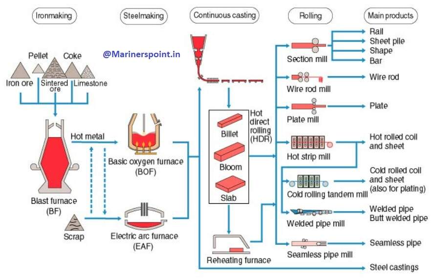
Steel Making Process – Complete Overview with Flowchart
| IC Engine | Important PDFs | Boilers | Synergy Maritime Exam | Naval Arch | MEO Class 4 |
| Interview Questions | Difference Between | Types of Pumps | Auxiliary Machines | Types of Valves | Home |