What is a DC motor ?
It is a device which converts electrical energy into mechanical energy. In today’s world of engineering and technology, a DC motor (direct current motor) has a wide range of applications. DC motors may be found in everything from electric shavers to automobiles. Different types of DC motors are employed depending on the application to accommodate to this vast range of applications.

What is the principle of DC motor ?
DC Motor Working Principle : When a current carrying conductor is placed in a magnetic field it experiences a mechanical force.
How to Find the Direction of Force Produced ?
The direction of force produced is given by Fleming’s left hand rule.
What is Fleming’s Left Hand Rule ?
Fleming’s Left Hand Rule : When the index finger middle finger and thumb finger of left hand are arranged mutually perpendicular to each other then the thumb gives direction of magnetic force index finger gives direction of magnetic field and middle finger give direction of current
Magnitude of Force is given by
F = BIL Sinθ
B is for magnetic field, I is for current, L is for length of conductor in magnetic field, θ is angle between magnetic field and current
What is Back EMF ?
When the armature is rotating the conductors are also cutting the magnetic flux line and hence according to Faraday’s law of electromagnetic induction and EMF is generated in the armature conductors in opposite direction of armature current . This is known as Back EMF
Back EMF is directly proportional to the speed of motor
Magnetic flux is the product of the average magnetic field and the perpendicular area that it penetrates
Faraday’s First law of Electromagnetic Induction
Whenever there is relative motion between conductor and a magnetic field the flux linkage with a coil changes and this change in flux induces a voltage across the coil
Faraday’s 2nd Law of Electromagnetic Induction
It states that the magnitude of EMF induced in the coil is equal to the rate of change of flux that linked with the coil.
Flux linkage of the coil is the product of number of turns in the coil and the flux associated with the coil
Significance of back EMF
Suppose the load of motor reduces suddenly then list stock will be required compared to the present talk. So the access talk will tend to increase the speed of the motor but the back EMF being proportional to the speed of motor also increases thereby decreasing the armature current and torque being proportional to the armature current will decrease and till it become sufficient for the load .
Similarly for the case of increased load.
Parts of DC motor
Stator – Stationary part of the motor which consists of the field winding and receives electrical supply
Rotor – Rotating part of the motor
Other parts are :
- Yoke – The outer frame of the motor is called yolk it provides covering for the inner part of the motor and also provide support to the armature it is made up of cast iron or steel.
- Magnetic Pole – It is fitted on the inner wall of the yoke. Consist of Pole core and pole Shoe. Pole core holds the pole shoes which has large surface area to spread the potential flux in the over the air gap between the stator and the rotor.
- Field Winding – Made up of Cu wire. Winded in the slots of pole shoes in such a manner that when the current flows through the adjacent pole, opposite polarity is produced.
- Armature Winding – Rotor is made of armature core and windings that is made with several low hysterisis silicon steel to minimize the magnetic losses like hystersis loss or eddy loss.
Types of Windings
There are two types of windings
| Lap Winding | Wave Winding |
| 1. Successive coils overlap each other | 1. The end of one coil is connected to the starting of another coil of the same polarity as that of first coil. |
| 2. All the pole groups of the coil generating EMF in the same direction at any instant are connected in parallel by brushes. | 2. Coils carrying current in one direction are connected in one series circuit and coils carrying current in opposite direction in other series circuit. |
| 3. No of parallel path = No of Poles | 3. Number of Parallel paths = 2 |
| 4. No of brushes required = No of poles | 4. No of Brushes = 2 |
Losses in DC Motor
1. Cu – Loss / Electrical Losses
These are the losses due to resistance in winding and includes Armature winding loss, Field Winding losses and brush contact losses.
2. Fe – Loss / Core Loss
It consist of two losses
A) Hysteresis Loss
It occurs in the armature windings due to the reversal of the magnetization of the core.
B) Eddy Loss
According to the faraday’s law of electromagnetic induction, due to relative motion between the armature core and magnetic flux, an emf is induced in the core which allow flow of charge on the body due to conductivity of the core. This current is useless and this loss is called eddy current loss. It can be minimized by laminated core.
3. Mechanical Losses
It consist of the losses due to friction between the bearings and commutator.
4. Stray Losses
These are the losses caused due to short-circuit connection of the coil, distortion of flux, inaccuracy in design of machine and other losses which are difficult to find.
Types of DC Motor
Separately Excited DC Motor
The field and armature windings are supplied separately in a separately stimulated DC motor, as the name implies. The armature current does not travel through the field windings in these sorts of DC motors because the field windings are activated by a separate external source of DC current, as indicated in the figure beside.
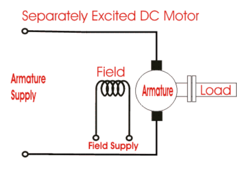
Tg = Ka φ Ia is the torque equation for a DC motor. In this scenario, the torque may be adjusted by changing the field flux φ, which is independent of the armature current Ia.
Permanent Magnet DC Motor
In this type of motor , inspite of having a field winding we have permanent magnets to provide magnetic field. The armature winding of a Permanent magnet DC motor (also known as a PMDC motor) is similar to that of a conventional motor, although the field windings are not always present. The field flux is produced by radially magnetized permanent magnets positioned on the inner periphery of the stator core in these sorts of DC motors.

Self Excited DC Motor
In the case of a self-excited DC motor, the field winding is linked to the armature winding in series, parallel, or partly in series, partly in parallel. Self-excited DC Motors can be categorised as follows:
- Shunt wound DC motor
- Series wound DC motor
- Compound wound DC motor
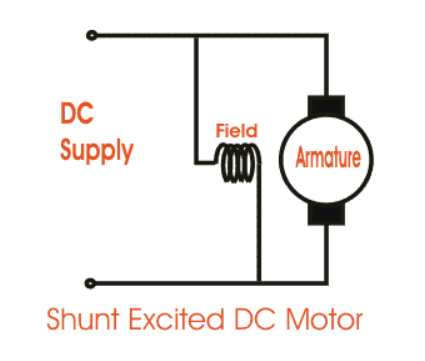
Shunt Wound DC Motor
In this the field winding is connected in parallel with the armature winding. It is of constant speed type motor.
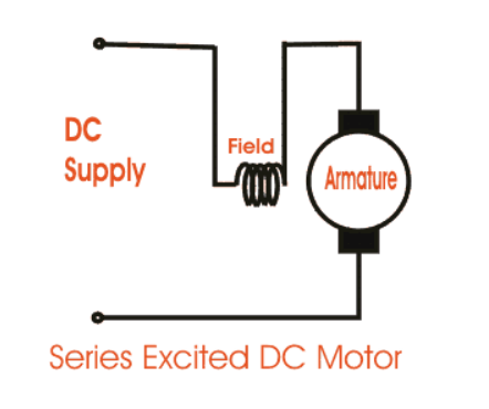
Series wound DC motor
In this type of motor, the field winding is connected in series with the armature winding. It’s speed varies with load.
Compound Wound DC Motor
The field winding is in combination of shunt and series wound dc motor. It has two types i.e Cumulative Compound DC Motor & Differential Compound DC Motor.
Cumulative Compound DC Motor
In Cumulative Compound DC Motor the field winding assist the flux of armature winding.

Differential Compound DC Motor
In Differential Compound DC Motor the field winding and armature winding are arranged in such a manner that the flux of field winding opposes the armature winding flux.
Because the net flux created in this scenario is less than the original flux, it has limited practical utility.
Short Shunt DC Motor
Short shunt DC motors, or more specifically short shunt type compound wound DC motors, have the shunt field winding just parallel to the armature winding and not the series field winding.

Long Shunt DC Motor
Long shunt type compounded wound DC motors, or simply long shunt DC motors, have the shunt field winding parallel to both the armature winding and the series field winding.

Speed Control of DC Motor
- Flux Control Method
- Armature Control Method
- Voltage Control Method
Flux Control Method
In this method, the magnetic flux due to the field winding is varied. As the magnetic flux produced in the field winding is proportional to the current flowing through it. So, the magnetic flux can be varied by varying the current, which is done by using a variable resistor in series with the field winding resistor.

Initially, when the variable resistor is kept minimum, the rated current flows through it and the speed of the motor is normal. But when the resistance is increased, less current flows through the field winding, so less flux is produced as speed of motor is inversely proportional to the flux produced, rpm increases.
Armature Control Method
In this method, the speed of the motor is controlled by controlling the armature resistance to control the voltage drop across the armature. When the variable resistor is at minimum, the speed of the motor is normal. But when the resistance is increased, the voltage across the armature decreases, which reduces the speed of the motor.

Voltage Control Method
In such method, the field winding receives a fixed voltage and the armature gets a variable voltage. This is done by :
A) Multiple voltage control
The shunt field is coupled to a fixed exciting voltage in this method, and the armature is supplied with various voltages. With the use of appropriate switchgear, the voltage across the armature can be altered. The voltage across the armature is roughly proportional to the speed.
B) Ward-Leonard System
This method is applied when precise motor speed control is required (e.g electric excavators, elevators etc.). The Ward-Leonard speed control system is based on the armature voltage control technique. M is the main dc motor whose speed must be controlled, and G is a separately stimulated dc generator in this system. A three-phase driving motor, which could be an induction or asynchronous motor, drives the generator G. The combination of ac driving motor and the dc generator is called the motor-generator (M-G) set.

Read More : Diesel Generator Working Principle
Also Read : TOP 50+ Frequently Asked IC Engine Interview Questions
Suggested Read : Centrifugal Pump | Parts | Working | Diagram
Check Out Other Important Topics
Home IC Engine Electrical Important PDFs Boilers Synergy Maritime Exam Naval Arch Interview Questions Difference Between Types of Pumps Types of Valves MEO Class 4 Auxiliary Machines