Electrical discharge machining process is non traditional method of removing metal from a work surface due to metal erosion caused by an electric spark discharge between the two electrodes of the tool (cathode) and the work surface (Anode).
What is Electrical Discharge Machining ?
Electric discharge machining, also known as spark erosion, electro-erosion, or spark machining, is a metal removal process that uses an interrupted electric spark discharge between the electrode tool cathode and the work anode to erode metals.
Fundamentally, the electric erosion effect is defined as the breakdown of electrode material that occurs as a result of any type of electric discharge.
The discharge is typically accomplished through the use of a gas, liquid, or, in some cases, solids. Ionization of the dielectric, or the splitting of its molecules into ions and electrons, is a necessary condition for producing discharge.
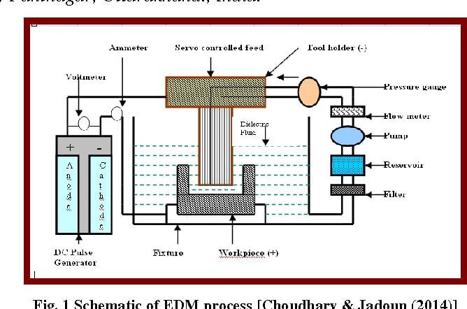
The electric power supply, the dielectric medium, the workpiece and tool, and servo control are the main components.
Parts of Electrical Discharge Machining
The main components are :-
- DC pulse generator
- Voltmeter
- Ammeter
- Tool
- Die electric fluid
- Pump
- Filter
- Servo controlled feed
- Fixtures
- Table
1. DC Pulse Generator
This is the source of power for the machining operation. DC power is provided.
2. Voltmeter
We know that the voltmeter measures voltage. The same device is used in this device.
3. Ammeter
It is used for measuring or checking the current flow. If the ammeter is not connected, we may not be able to see or check whether current is flowing or not.
4. Tool
A tool is connected to negative power sources, whereas the workpiece is connected to positive power sources. The fluid flows from the filter to the tool for operation.
When the power supply is increased, a spark is generated between the tools and the workpiece, and machining begins.
5. Di-electric field
It has an insulation property, and we all know what insulation is. Insulation means that no current flows from one to the other.
When the power supply is turned off, the di-electric fluid will be ionized in the form of an ion, which will help between the tool and the workpiece again.
6. Pump
The pump is connected there to transport the fluid to the filter. This is similar to moving fluid from one source to another.
7. Filter
The filter, as the name implies, is used to filter out various particles such as:
If dust particles are present in this device, the filter will remove them and send them to the tool for operation.
8. Servo Controlled Feed
The servo will supply the constant feed for the operation.
9. Fixtures
It is used for holding the table.
10. Table
Used for holding the workpiece.
Electrical Discharge Machining Working Principle
Electrical discharge machining is based upon the principle of electro discharge erosion (EDE) effect of electric sparks occurring between two electrodes that are separated by a dielectric liquid to remove materials.
Working of Electrical Discharge Machining
It is made up of an electric power supply, a dielectric medium, a tool, a workpiece, and servo control.
The workpiece is connected to the positive terminal of the DC power supply, while the tool is connected to the negative terminal.
An air gap of 0.005 to 0.05 mm is maintained between the tool and the work.
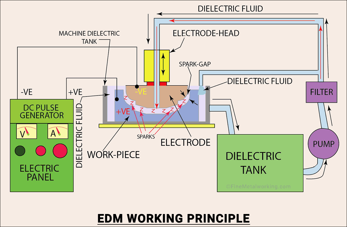
The di-electric fluid, which is a non-conductor of electricity, is forced through the gap under pressure.
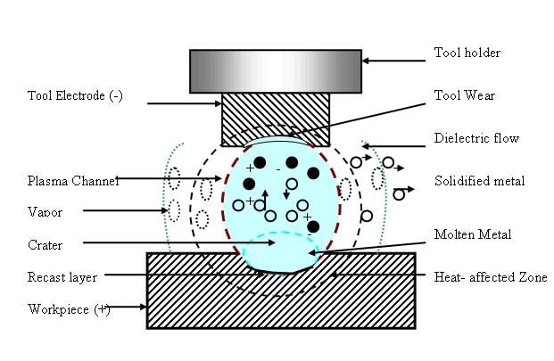
When DC power is applied, the fluid in the gap ionizes and produces a spark between the tool and the workpiece, causing a local temperature rise of about 1000 degrees Celsius, which melts and vaporizes the metal in a small area of the workpiece.
The DC supply generates a pulse with a voltage range of 40 to 3000 V, and a spark frequency of 10000 sparks per second can be achieved. When heated metal is subjected to electric and magnetic fields, a compressive force is generated, which removes the metal from the work surface.
The di-electric fluid serves as a coolant, transporting the cooled metal away from the work surface. The di-electric fluid acts as a coolant and transports the eroded metal particles, which are filtered on a regular basis and returned to the tank.
A servomechanism is used to feed the tool and keep the gap between two electrodes constant. This process can achieve an accuracy of about 0.005 mm.
Applications of Electric Discharge Machining
EDM has become an indispensable process in the modern manufacturing industry. It produces complex shapes to a high degree of accuracy in difficult-to-machine materials such as heat-resistant alloys, super- alloys, and carbides.
The incorporation of EDM within a computer-integrated manufacturing (CIM) system reduced the length of time that the unit operation, without stops for maintenance, is required.
Micromachining of holes, slots, and dies; procedures for surface deposition; modification; texturing; milling; and mechanical pulsing are typical applications.
Electric Discharge Machining (EDM) finds applications in various industries due to its unique capabilities. Here are some common applications of EDM:
- Mold and Die Making: EDM is widely used in mold and die making industries to create complex and precise cavities, shapes, and contours. It allows for the production of intricate details in molds for plastic injection molding, metal stamping dies, and forging dies.
- Aerospace Industry: EDM is employed in aerospace manufacturing to produce turbine blades, engine components, and other intricate parts with high precision. It is particularly useful for shaping difficult-to-machine materials like titanium and superalloys.
- Medical Device Manufacturing: EDM is utilized in the production of medical implants, surgical instruments, and other medical devices. It enables the creation of intricate features and contours required for implants like hip replacements and dental prosthetics.
- Automotive Industry: In automotive manufacturing, EDM is used for producing precision parts, such as gears, transmission components, fuel injection nozzles, and brake components. It allows for high accuracy and surface finish, critical for automotive applications.
- Electronics and Electrical Industries: EDM is employed in the production of precision electrical contacts, connectors, and microelectromechanical systems (MEMS). It can create fine details and microstructures required for electronic components.
- Tool and Die Industry: EDM is extensively used for tool and die manufacturing, including the production of punches, dies, and cutting tools. It enables the creation of complex shapes and profiles with high accuracy and repeatability.
- Prototype Development: EDM is a valuable tool for rapid prototyping and the creation of one-off or low-volume parts. It allows for the efficient production of prototypes with intricate geometries, aiding in product development and testing.
- Watchmaking and Jewelry Industry: EDM is employed in the production of intricate watch components and jewelry, where precision and fine details are crucial. It allows for the creation of complex shapes and engravings with high precision.
Overall, EDM is widely used in industries where high precision, complex geometries, and the ability to machine difficult materials are required. Its applications span across sectors such as manufacturing, aerospace, medical, automotive, electronics, and jewelry.
Advantages and Disadvantages of Electrical Discharge Machining
What are the Advantages of Electric Discharge Machining ?
- It can be used on any hard material, including heat-treated materials.
- Any complicated shapes created with the tool can be replicated. I
- t is possible to achieve a high level of accuracy of about 0.005 mm.
- Up to 0.2 microns of surface finish can be achieved economically.
- The machining time is shorter than the traditional machining process.
- This process generates no mechanical stresses (There is no contact between tool and work)
- Increased tool life as a result of proper lubrication and cooling.
- It is simple to create a hard, erosive-resistant surface on the dies.
- It is applicable to any electrically conductive material.
Disadvantages
- Tool wear is excessive.
- High power consumption in this process.
- The sharp corner cannot be replicated.
- The development of high heat results in a change in the metallurgical properties of materials.
- The workpiece must be an electrical conductor.
- Surface cracking may occur in some materials.
- Deep holes necessitate the redressing of a tool.
- An over-cut is formed.
- It’s difficult to find skilled machinists.
Electrical Discharge Machining Process Parameters
The four input parameters considered for the EDM experimentation are:
1. Pulse Current (A);
2. Pulse on time (µs);
3. Pulse off time (µs); and
4. Gap Voltage (V).
The above parameters were chosen on the basis of extensive literature surveys that have reported these parameters to be most influential for the MRR and the Ra.
What is Wire Electrical Discharge Machining Process?
Wire-cut Wire EDM is also known as EDM, wire cutting, EDN cutting, EDM wire cutting, wire burning, wire erosion, wire cut electric discharge machining, and ‘cheese-cutter’ EDM.
Wire electrical discharge machining (WEDM) uses a thin electrode wire to cut or shape a workpiece, usually conductive material, along a well planned path. Electrode diameters normally vary from.004′′ to.012′′, while smaller and larger sizes are available (.10mm to.30mm).
There is no direct contact between the wire and the workpiece throughout the wire cutting process, allowing for machining without producing any distortion in the wire’s course or the material’s shape. This is accomplished by rapidly charging the wire to the necessary voltage. Deionized water surrounds the wire as well. A spark jumps the gap and melts a small area of the work piece when the voltage reaches the necessary level. The deionized water cools the gap and flushes the tiny particles out.
The cutting speed is unaffected by the hardness of the work piece material. Wire cutting is commonly used to machine extrusion dies and blanking punches.
Frequently Asked Questions
What is Electric Discharge Machining Process ?
Electrical discharge machining (EDM) is a non-traditional machining process that involves removing material from a part through a series of repeated electrical discharges between tools known as electrodes and the part being machined in the presence of a dielectric fluid.
What materials can be machined by EDM ?
Any conductive material such as steel, titanium, aluminium, brass, alloys and super alloys can be cut using the EDM wire method. With its accuracy, the EDM wire cut technique has become a convention cutting method in all industries. Machine parts, logos and other metals can be cut and made with ease using EDM wire.
Electrical Discharge Machining MCQs
Q. How is material removed by electro discharge machining ?
a) Melt and evaporate
b) Corrode and break
c) Mechanical erosion takes place
d) None of the mentioned
View Answer
Answer: a
Explanation: In Electro discharge machining, material is melted and then evaporated.
Q. In electrical discharge machining the temperature developed is of the order of
A. 2,000°C
B. 6,000°C
C. 10,000°C
D.14,000°C
Answer : c
When two electrodes are moved close enough together and the voltage is high enough, the dielectric fluid breaks down and conducts electrical current, resulting in an electrical discharge or spark that produces extremely high temperatures in the order of 10,000 °C at a localized zone on the workpiece material.
Q. In electrical discharge machining process the metal removal is carried out by
A. electrolysis
B. melting and vaporization
C. fracture of work material due to impact of grains
D. none of the above
Answer: B
In Electrical Discharge Machining (EDM) process, the metal removal is carried out by melting and vaporization as there is a controlled erosion between two electrically conducting materials, the tool and the workpiece.
– In Electro-Chemical Machining (ECM) process, the metal removal is carried out by electrolysis
– Whereas in Ultrasonic Machining (USM) process, the metal removal is carried out by fracture of work material due to impact of grain
Check Out Other Important Topics
Water Jet Machining – Working Principle, Applications, Advantages
Abrasive Jet Machining – Parts, Working Principle, Application
Ultrasonic Machining Process – Parts Working Principle, Advantages
What is Process Planning | Process Planning Steps, Types, Advantages
What is Cold Working – Methods & Working Processes
What is Hot Working ? Methods & Processes
Forging Operations – Types, Methods, Advantages, MCQs
Steel Making Process – Complete Overview with Flowchart
| IC Engine | Important PDFs | Boilers | Synergy Maritime Exam | Naval Arch | MEO Class 4 |
| Interview Questions | Difference Between | Types of Pumps | Auxiliary Machines | Types of Valves | Home |