In this article we are going to discuss about Fits, types of fits and their sub types, Classification of Fits under Newall System, How to Name Different Types of Fit in Mechanical Engineering.
What is Fit ?
The relationship between two parts where one is inserted into the other with a certain degree of tightness or looseness is known as fit.
Engineered products are sometimes delivered in the form of components that must slip or press against one another in order to perform their functions. As a result, the term “fit” is used to describe the dimensional relationships between the components. It determines whether the components are loose or tight, which aids in the slipping or pressing property. Understanding what a fit entails understanding a few terms, which are defined below.
Types of Fits
Depending upon the actual limits of the hole or shaft, the types of fit in the Indian Standard and in the British Standard, shall be divided into three main classes as follows :(Fig. 15.4).
- Clearance Fits
- Interference Fits
- Transition Fits

1. Clearance Fits
In a clearance fit there is a positive allowance between the largest possible shaft and the smallest possible hole. With such fits the minimum clearance is greater than zero. Such fits give loose joints, i.e., there must be some degree of freedom between a shaft and a hole.

What is Tolerance Zone ?
Assume we need to make a 10 mm nut to fit a 10 mm bolt. However, due to human and machining error, the inside diameter became 9.98mm. As a result, the nut will not fit into the bolt, and our joint will be ruined. To avoid this error, tolerance zones are used.
We define a tolerance zone in which the tolerances of nuts and bolts are a little bit even, so that they fit and maintain interchangeability between two parts.
Now let’s talk about Clearance fit.
There is a large gap between the tolerance zone of the hole and the tolerance zone of the shaft in this case.
So we call it a clearance fit if the hole is larger than the shaft and allows the two mating parts to rotate or slide over each other.
When it comes to clearance fit, the minimum size of the hole is always greater than the maximum size of the shaft.
In any case, when we assemble the shaft and hole, we will get the clearance that a shaft can easily slide while also rotating inside the hole.
As a result, we can easily make running and sliding fits in the clearance fits. Consider the piston and valve.
Types of Clearance Fits
Clearance fits may be subdivided as:
- Slide fit.
- Easy Slide fit.
- Running fit.
- Slack running fit
- Loose running fit.
1. Sliding Fit
These types of fit has very little clearance between two parts, almost none, but it provides much greater precision and accuracy in sliding and moving parts.
Example :- Sliding gears, automobile assemblies, slide valves, clutch discs, machine tool parts, tailstock spindle of the lathe machine, shaft guiding, etc.
2. Easy Slide
For a small clearance between the hole and the shaft, an easy slide is used. The easy-slide has been used for both non-regular and slow regular motions. Example :- piston.
3. Running Fit
When rotating components at a moderate speed, the running fit must be used where accuracy is not required. Running fit has a high clearance and involves large temperature variations, high running speeds, and heavy journal pressures. Example :- Gears, couplings .
4. Slack Running Fit
These types of fit provides very close and minimal clearance for precise requirements, and with the help of lubrication, parts can be assembled without force and turn and slide freely. Example :- guiding of shafts, roller guides etc.
5. Loose Running Fit
Loose running fits are used for parts that rotate at high speeds and have a larger clearance when accuracy is not critical. Example :- Latches, pivots, heat, parts affected by corrosion and contamination etc.
2. Interference Fits
In Interference Fit, the tolerance zone of the shaft exceeds the tolerance zone of the hole. This means that the shaft is large and the hole is small.
We needed a lot of force to assemble and disassemble these two, so we used a hammer. Another method is to use a hydraulic press to insert the shaft into the hole.
In an interference fit there is a negative allowance or interference between the largest hole and the smallest shaft, the shaft being larger than hole.
Types of Interference Fits
Interference fits may be classified as: (1) force fit, (2) Tight fit and (3) Driving fit.
1. Force Fit
To achieve the high interference fit, the part must be heated to a very high temperature before being assembled with a hole. External force is required for the mating parts.
Example: Gears, shafts, etc.
2. Tight Fit
It provides minimal interference than force fits.
For Example: Stepped pulley of a conveyor, cylindrical grinding of a machine, etc.
3. Driving Fit
It requires medium interference, which can be assembled using higher forces for cold or hot forging. Driving fits are more reliable than tight fit.
Example: Shafts, gears, and bushes etc.
3. Transition Fits
Transition fits cover cases between the first two classes (Fig. 15.4). The use of transition fits does not guarantee either an interference or a clearance, i.e., any pair of parts of mating with a transition fit may fit with interference, while another pair with the same fit may have a clearance fit.
In a transition fit, the tolerance zone of the shaft lies between the lower and middle of the tolerance zone of the hole, indicating that the hole is smaller than the shaft.
To make this fit, we must apply slight pressure to the shaft as it enters the hole. We also refer to it as Push Fits. Transition fit has high precision and accurate alignment between two mating parts. for example :- shaft key.
Types of Transition Fits
Transition fits may be classified as : (1) force fit, (2) tight fit, (3) wringing fit and (4) push fit.
Classification of Fits under Newall System
The four types of fit under the Newall system are as follows:
1. Running Fit
A running fit is a smooth, easy fit for the purpose of a moving bearing pair. For a sliding or running fit, the diameter of the shaft should be enough smaller to allow for a film of oil for lubrication. For an average length of bearing, an allowance of 0.025 mm per 25 mm of a diameter of bearing is sufficient.
2. Push Fit
In a push fit one can be assembled into the other with light hand pressure (locating plugs, dowels, etc.), there being no sufficient clearance to allow the shaft to rotate.
3. Driving or Press Fit
In a driving or press fit one can be assembled into the other with a hand hammer or by medium pressure. It gives a semi-permanent fit such as is necessary for a keyed pulley on a shaft.
4. Force Fit or Shrink Fit
Force fit requires either great pressure to force the shaft into the hole or the hole to be expanded by heating so as to shrink them on the shaft. So this is also called hot fit. These types of fit are used when the two parts are to be rigidity fixed together so that one cannot move without the other. In a force fit, the shaft is definitely larger than the hole. Railway and tram car wheels and cart wheels are fitted under this method.
Hole and Shaft Basis System
In a general limit system it is necessary to decide on what basis the limits are to be found to give the desired fit. There are two distinct systems for varying the sizes of parts known as: hole basis and shaft basis.
A limit system is said to be on a hole basis when the hole is constant member and different fit are obtained by varying the size of the shaft. In this hole system the high and low limits are constant for all types of fit of the same accuracy grade and for the same basic size.
A limit system is said to be on a shaft basis when the shaft is the constant member and different fits are obtained by varying the size of the hole. In this shaft system the high and low limits are constant for all fits of the same accuracy and grade and for the same basic size. Both hole and shaft basis are illustrated in Fig. 15.5.

All modern limit systems employ the hole basis, the chief reason being that it is easier to vary the size of the shaft than that of the hole. The majority of holes in engineering work is produced with drill and reamer or some similar tool and to vary the size of holes would necessitate the use of a very large number of tools of varying sizes. By employing hole basis one size reamer suffices for all the holes to any particular diameter. However, in some instances the shaft basis system proves to be more advantageous to use than the hole basis system.
Fits, Allowance, Clearances & Interferences

In dealing with two mating surfaces or parts, one which enters into the other is known as the enveloped surface or male part, and the other in which one enters is the enveloping surface or female part. The enveloped surface of a cylindrical part is considered as a shaft while the enveloping surface as a hole. The dimensions corresponding to them are called a shaft diameter and a hole diameter. In the case of a key and its key way, the key represents a shaft, while the key way represents a hole.
Fits
The relationship between two parts where one is inserted into the other with a certain degree of tightness or looseness is known as a fit. Depending on how the parts mate, fits can provide for different degree of freedom of movement.
Allowances
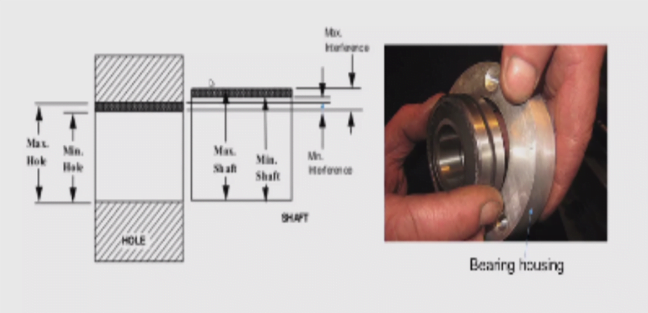
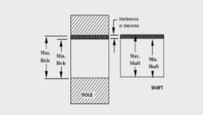
An intentional difference between the hole dimension and shaft dimension for any type of fit is called the allowance (Fig. 15.4) If we subtract the minimum shaft size from the largest hole size we obtain the maximum allowance, while the minimum allowance is the difference between the largest shaft and the smallest hole size.
An allowance may be either a positive (+) or a negative (-) amount according to the type of fit required. If the conditions are such that the shaft is smaller than the hole it is said that there is positive allowance, but if the shaft is larger than the hole it is said that there is negative allowance.
Clearances
A positive difference between the diameters of the hole and the shaft, the hole diameter being larger than the shaft diameter, allowing relative movement between the parts, is called a clearance as shown in Fig. 15.4.
The positive difference between the maximum limit size of a hole and the minimum limit size of a shaft is known as the maximum clearance. Similarly, the minimum clearance is the positive difference between the minimum limit size of the hole and the maximum size of the shaft.
The mean clearance is the arithmetical mean of the maximum and minimum clearances.
Interferences
A negative difference between the diameters of the hole and the shaft, the shaft diameter being larger than the hole diameter, is called an interference as shown in Fig. 15.4.
The maximum interference is the negative difference between the maximum limit size of the shaft and the minimum limit size of the hole. Similarly, the minimum interference is the negative difference between the minimum limit size of the shaft and the maximum limit size of the hole. The mean interference is the arithmetical mean of the maximum and the minimum interference.
How to Name Different Types of Fit in Mechanical Engineering
Understanding how they name the various types of fit is critical because it aids in selecting the correct types of fits for assembling a product.
An alpha-numeric code, according to the International Organization for Standardization (ISO), names a specific fit and denotes the fit’s tolerance. The hole or shaft is represented by the alphabet portion of the code.
A code with an upper-case letter represents the hole, while a code with a lower-case letter represents the shaft. For example, H7/h6 is a tolerance range for the hole (H7) and shaft (h6), respectively, based on the letter used. This code will also allow engineers to identify the hole’s and shaft’s upper and lower size limits.
We tried to cover all details starting from definition of Fits, Different types of fit, Naming convention and all the terms associated with it. Hope you loved this article. Please share it with your friends and give your feedback in the comment below.
Check Out Other Important Topics
Foundry Tools And Equipment – List, Names & Images
Sand Testing Methods – Full Process
Types of Casting Defects – Complete Overview
Moulding Sand – Properties, Types, Process, MCQs
Plant Layout – Types, Objectives, Principles, Advantages
FAQ
| IC Engine | Important PDFs | Boilers | Synergy Maritime Exam | Naval Arch | MEO Class 4 |
| Interview Questions | Difference Between | Types of Pumps | Auxiliary Machines | Types of Valves | Home |