In this article we are going to discuss about Coupling, Types of coupling, Shaft Coupling, Working and construction with Images. Let’s start with defining What is coupling?
What is coupling ?
A coupling is a device that connects two shafts at their ends in order to transmit power. Couplings’ primary function is to connect two pieces of rotating equipment while allowing for some degree of misalignment, end movement, or both.
What is Shaft Coupling ?
A shaft coupling is a mechanical component that connects two shafts in order to accurately transmit power from the drive side to the driven side while absorbing mounting error (misalignment), etc. of the two shafts.
The shaft coupling is a mechanical component that connects two rotating shafts, such as the driving and driven shafts, for the purpose of power transmission. It is found in motors, pumps, generators, and compressors, among other things.
The shaft coupling connects the electric motor and the pump hydraulic system. Slip-free shaft couplings for centrifugal pumps are classified as rigid or flexible.
Functions of Coupling ( Shaft Coupling )
1. Transmission power :- Transmission of power from the driving side (turning side) to the driven side (turned side).
The main purpose of a coupling is to connect the drive shaft to the driven shaft.
It is difficult to manufacture a machine that is connected with a one-piece shaft rather than a coupling. It causes issues in terms of cost and accuracy, but it also makes transportation and assembly difficult, necessitating additional man-hours.
In addition, if either the drive or driven side of a one-piece shaft is broken, it must be replaced in its entirety.
2. Absorb misalignment :- Mounting errors between the axes of the driving side (turning side) and the driven side are absorbed (turning side).
It takes a long time to precisely align the drive shaft to the driven shaft.
If the axes of two shafts are misaligned, an extra force is applied to the surrounding parts as it rotates, causing vibration and noise. Furthermore, even though the same parts are used to manufacture units, there are errors such as machining accuracy, making it very difficult to assemble every unit with accuracy because the dimensions differ one by one. As a result, a coupling should be used to absorb such mounting errors.
The coupling’s role is to transmit power dynamically and accurately even if the two shafts are misaligned (eccentricity / declination angle, axial displacement, etc.).
3. Absorb vibrations to protect surrounding products :- Absorbs vibration from the driving side (turning side) and protects surrounding products.
When using the machine, vibration and shock may be transferred to surrounding parts. For example, if the vibration of a motor, etc. in the driving side is transmitted to the ball screw, etc., it causes the machine to deviate from the prescribed position and makes good use of the machine’s performance impossible.
In addition, if a machine with no coupling is hit from the outside, the impact may be transmitted directly to the motor, causing damage to the motor. The solution to this problem is a coupling. It absorbs vibration in order to move the driven side with high accuracy, and/or shock in order to protect expensive motors and other components.
4. Do not transfer the heat of the motor, etc. to the driven side :- Does not transfer heat from the motor on the drive side (turning side), etc. to the driven side (turned side).
When a motor is used, it generates a lot of heat. When it is transmitted to the driven side, the ball screw and other components expand due to heat and their lengths change. As a result, positioning accuracy suffers, and the expected machine precision is not met. However, by using a coupling, it is possible to prevent heat transfer from the motor, etc., so that the parts are not deformed or shifted from their proper position.
How does a Shaft Coupling Works ?
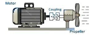
As shown in the diagram above, coupling can be used to connect two shafts. It is not a problem if the shaft diameters differ.

According to the diagram above, the motor is on the driving side and the propeller is on the driven side.

The coupling does not transfer the heat etc. of the motor to the driven side.

Coupling did the work of absorbing the shock and vibration from transferring, this will help to protect surrounding components from damage.
Types of Coupling
1. Rigid Coupling

Rigid couplings are used to connect two shafts when they are in perfect rigid axial alignment.
Rigid couplings are a types of coupling that should be used only when the shafts are perfectly aligned. A rigid coupling is only appropriate for shafts that are in close alignment or are held in alignment. Torque will be transferred to the shafts and bearings if they are not aligned, resulting in premature failure.
There are two principal types of rigid coupling :
A. Muff coupling, and B. Flange coupling
2. Muff coupling

A muff coupling / Sleeve Coupling is the simplest type of rigid coupling, consisting of a hollow cylinder with the same inner diameter as the shaft. It is fitted over the ends of the two shafts by the means of a gib head key. Power is transmitted from one shaft to the other shaft by means of a key and a sleeve or muff.
It is the simple type of rigid coupling ,made up of cast iron. It consists of a hollow cylinder whose inner diameter is the same as that of the shaft. It is fitted over the ends of the two shafts by a sunk key.
Simply, A muff coupling or box coupling, consists of a solid box or muff made of cast iron, bored out to fit the shafts whose ends are made to butt together inside the box. The box may be secured to the shaft by means of a sunk key which extends the whole length of the box. Sometimes two keys are used to fit the muff on the shafts.
The power is transmitted from from one shaft (drive ) to other shaft (Driven) by means of a key and sleeve.
3. Split Muff or Compression Coupling

Split muff couplings are also known as compression couplings or clamp couplings. It is a type of rigid coupling.
The sleeve in this coupling is made of two halves. The muff’s halves are made of cast iron. The muff is attached from below, and the other half is attached from above.
Mild steel studs or bolts and nuts hold the two halves of the sleeve together.
The number of bolts can range between four and eight. They are always divisible by four. The bolts are inserted into recesses cut into the sleeve halves.
The advantage of these types of coupling is that the position of the shafts does not need to be changed when the coupling is assembled or disassembled. This coupling is suitable for both heavy duty and moderate speeds. It is cheaper than other types of coupling. It has compact construction with small radial dimensions. It has no projecting parts except the key head.
4. Flange Coupling
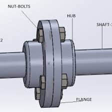
Flange coupling is a type of connector that connects two turning clutches with different flange arrangements. At the ends of shafts, flanges are fitted or provided. A number of nuts and bolts are used to secure the flanges together. At the end of each shaft, one of these flanges or chutes is fixed.
What types of coupling is flange coupling ?
Flange coupling is a type of shaft coupling having two separate flanges which are mounted on the shaft end and both flanges are bolted together by means of nuts and bolts
Parts of flange coupling
The “Flange Coupling” is very simple to describe. It is made up of two hubs (that fit on the equipment shafts), with those hubs being machined with a multi-bolt flange on one end. When the equipment is “coupled”, the flanges are bolted together and basically become ONE LARGE MASS!
Construction
It is made up of two cast iron flanges that are attached to the ends of each shaft. To complete the drive, the two flanges are bolted together with bolts. A flange coupling connects two tubes in a sealed manner.
One of the flanges has a projected portion part, and the other has a similar recess. Each flange end is joined together to ensure that they are correctly aligned without causing resistance in the material being passed through them.
It aids in aligning the shaft and bringing it into the same line. Nuts and bolts connect the two flanges. These couplings are commonly used in pressurized piping systems. It is also used for heavy loads, so it is very useful for large shafting.
Different type of flange coupling are following
- Unprotected type flange coupling
- Protected type flange coupling
- Marine type flange coupling
5. Flexible Coupling

Flexible coupling are used to protect the driving and driven machinery from detrimental effects, which may arise from misalignment of shafts, vibration, sudden shocks loads, end float, or shaft Expansion. The most extensively used of all types of flexible coupling is probably the crown-pin type coupling is shown in the figure.
One or both half of the coupling are provided with the studs engaging in holes in the other half. Studs have insulating and renewable flexible driving surfaces built up of leather washers or similar materials. This construction permits some axial movement and take care of starting shock or slight misalignment. Another advantage is that it can quickly be disconnected by removing the driving pins.
Other types of flexible couplings are : belt-type flexible coupling used to transmit medium power at low speeds ; internal gear type flexible coupling used for heavy drives such as in rolling mills, cement Mills, etc. and Bibley coupling applied universally to machinery and shafting drives upto the largest powers.
6. Bushed Pin Type Coupling

A Flexible Pin Bush Coupling is a type of Power Transmission Mechanical Coupling used to connect two shafts together at their ends for the purpose of transmitting power.
The bush pin type flexible coupling is an alteration on the flange coupling described above. In place of the nuts and bolts in the flange coupling, the Bush coupling has a rubber bush and pins and nuts.
The rubber bush allows the flange coupling to be flexible.
The flexible flange coupling is made up of two flanges, one keyed to the input shaft and the other to the output shaft. Depending on the diameter of the shaft, the two flanges are joined together with 4 to 6 bush and pins.
A nut is used to secure the pins to the flange. To prevent rubber bush wear, the inner surface of the rubber bush is lined with brass.
A key is used to secure the flange hub to the shaft.
In general, a 5 mm clearance is maintained between the coupling’s two flanges. For starters, there is no rigid connection between the two flanges, and power is transmitted via rubber bushes.
The coupling becomes more flexible as a result of this.
Advantages
- Its construction is simple
- It absorbs shock and vibration during power transmission.
- These types of coupling can handle misalignment of 0.5 mm laterally and 1.5 degree angular misalignment.
Disadvantages
- It is not economical i.e. its cost is high due to more components.
- Radial space required by the coupling is more as compared to other couplings.
7. Universal Coupling

Hooke’s coupling is another name for the universal coupling. It is used when the axes of two shafts intersect at a small angle. In theory, the inclination of two shafts can be constant, but in practice, this changes when motion is transferred from one shaft to another.
When it comes to connecting shafts at an angle, the universal coupling is one of the most versatile couplings. It can be used for shafts that are 90 degrees apart.
The figure above depicts a universal joint. These types of coupling are widely used in power transmission. The universal coupling is found in the transmission of the automobile from the gearbox to the differential. Two universal joints are used on each end in these cases. One at the propeller shaft’s end to the gearbox and one on the differential to the opposite end.
Universal coupling is also used to transmit power to various spindles on multiple drilling and milling machines.
It also enables efficient power and torque transmission between misaligned shafts at any angle, hence the name universal coupling.
8. Oldham Coupling

The Oldham coupling is another types of coupling designed to join two shafts having lateral misalignment. It was invented by John Oldham in Ireland in the year 1821.
Jaw couplings are being replaced by Oldham’s coupling. The Oldham’s coupling is an inversion of double slider crank chain mechanism.
The coupling is made up of three parts: two flanges and a central disc. Keys connect the two flanges to the shafts. The flanges have inner grooves, as shown in the figure.
The center disc, on the other hand, has projections made onto it. These projections fit into the grooves cut into the flanges. As a result, the center disc is sandwiched between the two flanges, and it is also free to slide in the grooves as shown below.
The flanges are made of stainless steel or an aluminum alloy. The central disc, on the other hand, is made of polymers or plastics. This reduces friction between the flange and the center disc while sliding. It also adds flexibility to the coupling.
Advantages
- Its size is compact.
- Easy to assemble.
- In case of excessive load, the center disc will be the one to break first. Thus preventing the failure of other important machine components.
- The center disc can be replaced easily and is inexpensive.
- It can effectively absorb shocks and vibrations.
- It can tolerate misalignment in shafts.
- Due to the presence of plastic center disc, the coupling becomes electrically insulated.
- It is economical.
Disadvantages
- It cannot tolerate angular misalignment.
- It cannot tolerate high torque.
- Due to the sliding movement, the center disc is subjected to wear, thus after a particular time period, it has to be replaced.
Applications
- It is used in a stepper motor.
- In robotics.
- Servo motor applications.
- In printers and xerox machines.
9. Gear Coupling
A gear coupling is a device that connects two shafts at their ends in order to transmit power. Couplings do not normally disconnect or allow couplings to disconnect from shafts while in operation; however, there are a few torque limiting couplings that slip or disconnect when a torque limit is exceeded or a problem arises.
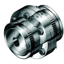
The gear coupling is a variant of the flange coupling. Because of the large size of the teeth, gear couplings can transmit a lot of torque. In this type of shaft coupling, the flange and hub are assembled separately rather than as a single part as in flange coupling.
Coupling Gears
Each joint is built with a 1:1 gear ratio internal and external gear pair. Furthermore, gear coupling is limited to angular misalignments of approximately 0.01-0.02 inch in parallel and 2 degrees in angular.
For similar applications, gear couplings and universal joints are used. These are typically used in heavy-duty applications where high torque transmission is required.
What is the functions of gear coupling
The basic function of a Gear coupling is to provide a mechanical connection between two rotating shafts. They use gear mesh for transmitting power and torque between the connected shafts. Hence, gear Coupling is a mechanical device that transmits torque between two shafts by using gears.
Types of gear coupling
Gear couplings customarily come in two varieties, flanged sleeve and continuous sleeve
Where are gear coupling are used ?
Gear couplings are commonly employed on large, industrial machines such as pumps, blowers, compressors, mixers, etc. They can be used in smaller motion control systems, mostly with a polymer sleeve as a means of reducing backlash but other zero-backlash coupling designs are usually better suited to these applications.
10. Bellow Coupling

Bellows couplings are a type of flexible coupling that has twin coupling ends called hubs that cap a precision-engineered corrugated tube that serves as the coupling body. Bellows couplings are well-known for their exceptional torsional rigidity, which allows them to accurately transmit velocity, angular position, and torque.
What are below coupling are used for ?
Bellows couplings are single-piece flexible shaft connectors that are used to couple driving and driven shafts in mechanical power transmission assemblies. Flexible shaft couplings are used to counter the inevitable misalignment that occurs between connected shafts and, in some cases, to absorb shock.
Bellows couplings are the types of coupling with twin coupling ends known as hubs. These couplings have high torsional rigidity and can transmit velocity, angular position, and torque accurately. They are typically constructed of stainless steel. These couplings are used in applications requiring high precision positioning.
Bellows couplings have thin walls and are only slightly flexible in the case of angular, axial, or parallel misalignment. The coupling bellows are welded to the hubs. The torsional stiffness of these couplings is the highest of any servo motor coupling.
11. Jaw Coupling

A jaw coupling is a type of power transmission coupling that can also be used in motion control applications. It is intended to transmit torque while dampening system vibrations and accommodating misalignment, thereby preventing damage to other components.
What is a jaw coupling used for ?
Jaw and Spider Couplings. Jaw & Spider (or Jaw-Type) couplings are a common type of shaft coupling in the industry. They are designed to transmit torque and rotation between two shafts, accept shaft misalignment, and help protect components from damage by damping shock and vibrations.
How does a jaw coupling work ?
The element in jaw couplings is loaded in compression between the jaws of mating hubs. The driving hub jaws push toward the driven hub jaws as they operate in the same plane. By being compressed between the driving and driven jaws, the elastomeric spider’s legs transmit and cushion the force between them.
This coupling is used for general-purpose power transmission as well as motion control applications. The jaw coupling is intended to transmit torque while reducing system vibrations and adjusting misalignment, thereby protecting other components from damage.
Jaw coupling is made up of two metallic hubs and an Elastoplast insert known as an element, also known as a “spider.”
Advantages
- This system is capable of handling angular misalignment as well as reactionary loads caused by misalignment.
- Has a good torque to outside diameter capability.
- Excellent chemical resistance and dampening capability.
12. Diaphragm Coupling

Diaphragm couplings are one type of nonlubricated coupling used in high-performance turbomachinery for torque transmission and misalignment of equipment shafts.
This coupling transmits torque from the outside to the inside diameter, and then from the inside diameter to the outside diameter.
The flexible members in diaphragm couplings are made up of a single or a series of plates. Misalignment of the diaphragm can be angular, axial, or parallel. These types of coupling are used when high torque and speed are required.
A diaphragm coupling is made up of one or more metallic membranes that are attached to the outside diameter of a drive flange and transfer torque radially through the diaphragm to an attachment on the inside diameter. The disk coupling is another type of metallic membrane coupling.
How does a diaphragm coupling work ?
Diaphragm couplings have flexible members that are made up of a single or multiple plates or diaphragms. It transmits torque from the outside to the inside diameter of a flexible plate, across the spool or spacer piece, and then from inside to outside diameter.
13. Fluid Coupling
A fluid coupling, also known as a hydraulic coupling, is a hydrodynamic or ‘hydrokinetic’ device that is used to transmit rotating mechanical power. It has been used as an alternative to a mechanical clutch in automobile transmissions.
Functions of fluid coupling
Fluid coupling, also known as hydraulic coupling, is a hydrodynamic device that uses transmission fluid to transfer rotational power from one shaft to another. It is used in automotive transmission systems, marine propulsion systems, and power transmission in industries.
Working principle of fluid coupling
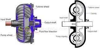
A fluid coupling or hydraulic coupling is a device used for transmitting power from one shaft to another shaft by means of acceleration and deceleration of a hydraulic fluid. Fluid coupling is based on hydro-kinetic principles and requires that the output speed be less than the input.
It is made up of an impeller mounted on the driving shaft (input) and a runner mounted on the driven shaft (output). The impeller functions as a pump, while the runner functions as a turbine.
The tangential component of absolute velocity is low in impellers near their axes. Where the tangential component of absolute velocity is high near the impeller’s periphery, the fluid velocity increases as the impeller accelerates.
As velocity increases, so does kinetic energy. The fluid exits the impeller at high velocity, strikes the runner blades, transfers energy, and exits the runner at low velocity.
Why Shaft Coupling is Used ?
The following are some of the most common reasons for using shaft coupling:
- Used to connect shafts of separate units, such as a motor and generator.
- For the misalignment of the shafts.
- For mechanical flexibility
- Absorbs shock loads transmitted from one shaft to another.
- Protections from overload.
Applications of Coupling
1. Sleeve and Muff Coupling Line shafts are used in power transmission.
2. Clamp or split-muff or compression coupling line shaft are used in transmission of power.
3. Flange coupling used for alignment accuracy . For example : In marine.
4. Bushed Pin Flexible Coupling which are Used for connecting which have small parallel misalignment, angular misalignment, or axial misalignment.
5. Universal Coupling which are Used for transmitting rotary motion or power, e.g., aircraft, driveshafts, etc.
6. Oldham’s Coupling are Useful in applications where parallel misalignment exists, e.g., Printing Application.
We have tried to provide you with the complete details about the different types of coupling that are available and what are their advantages and disadvantages along with proper Images. Hope you loved this article. Please let us know about the feedback in the comment below.
Check Out Other Important Topics
Plant Layout – Types, Objectives, Principles, Advantages
Types of Punches – Uses, Working, Applications, Pictures
Types of Dies – Classification, Uses, Pictures
Types of Rivets – Working & Their Uses [with Images]
Types of Fasteners – Uses & Examples [with Pictures]
| IC Engine | Important PDFs | Boilers | Synergy Maritime Exam | Naval Arch | MEO Class 4 |
| Interview Questions | Difference Between | Types of Pumps | Auxiliary Machines | Types of Valves | Home |