
Rapid prototyping is a technology used to create physical models of a product or a part of a product through a computer-aided design (CAD) software. This process helps in verifying the design and functionality of the product before its mass production. Rapid prototyping has gained immense popularity in recent years due to its efficiency, cost-effectiveness, and speed. In this article, we will discuss the definition, process, types, and techniques of rapid prototyping.
What is Rapid Prototyping ?
Rapid prototyping is the process of quickly creating a physical model or a part of a product using a computer-aided design (CAD) software. The CAD model is sliced into several cross-sectional layers, and each layer is built layer-by-layer using various techniques such as 3D printing, CNC machining, injection molding, and sheet metal fabrication. Rapid prototyping helps in verifying the design and functionality of the product before mass production, which reduces the risk of errors and saves time and cost.
The capabilities of Rapid Prototyping techniques can be listed as shown below :
- Substantially reduce product development time, through rapid creation of 3 D models.
- Improve communication ( visualization ) within multidisciplinary design teams.
- Address issues of increased flexibility & small batch sizes, while remaining competitive ( rapid manufacture ).
What are the basic principles of rapid prototyping?
Rapid prototyping is a process that involves creating physical models of a product using digital design and manufacturing technologies. Here are the basic principles of rapid prototyping:
- Iterative design: Rapid prototyping involves creating and testing multiple prototypes to refine and improve the design. This iterative process allows for quick and efficient development.
- Use of digital models: Rapid prototyping relies on digital models to create physical prototypes. These digital models can be quickly modified and adapted to create new designs.
- Fast production: Rapid prototyping allows for the quick production of physical models, reducing the time required for traditional manufacturing processes.
- Variety of materials: Rapid prototyping can use a variety of materials, including plastics, metals, and composites, allowing for a wide range of design options.
- Customization: Rapid prototyping allows for customization and personalization of designs, making it an ideal tool for creating prototypes for specialized or unique applications.
By following these principles, designers and engineers can create functional prototypes quickly and efficiently. The iterative design process allows for the rapid development of prototypes, enabling designers to test and refine their designs in a shorter time frame. The use of digital models also makes it easier to make changes to the design, further speeding up the prototyping process. Additionally, the ability to use a wide range of materials and customize designs makes rapid prototyping a versatile tool for a variety of applications.
Rapid Prototyping Process
The basic process : Although several rapid prototyping techniques exist, all employ the same basic five-step process. Figure below shows the conceptual representation of a Rapid Prototyping technique. The steps are listed here under:
- Create a CAD model of the design.
- Convert the CAD model of STL format
- Slice the STL file into thin cross-sectional layers
- Construct the model through layer by layer
- Clean and finish the model

1. Create a CAD model of the design
The first step in rapid prototyping is to create a 3D CAD model of the product using software such as SolidWorks, AutoCAD, or Pro/ENGINEER. The CAD model is created based on the design requirements, and it includes all the necessary details such as dimensions, material properties, and surface finish.
2. Convert the CAD model to STL format :
The various CAD packages use a number of different algorithms to represent solid objects. To establish consistency in the STL (stereolithography, the first Rap technique ) format has been adopted as the standard of the Rapid prototyping industry. The second step, therefore is to convert the CAD file into STL format. This format represents a three-dimensional surface as an assembly of planar triangles, “likes the facets of a cut jewel” .
The file contains the coordinates of the vertices and the direction of the outward normal of each triangle. Because STL files use planner elements, they cannot represent curved surfaces exactly. Increasing the number of triangles improves the approximation, but a the the cost of bigger file size. Large, complicated files require more time to preprocess and build, so the designer must balance accuracy with manageability to produce a useful STL file. Since the STL file format is universal, this process is identical for all of the RP build techniques.
3. Slice the STL file into cross-sectional layers :
In the third step, a pre-processing programs the STL file to be built. Several programs are available , and most allow the user to adjust the size, location and orientation of the model. Build orientation is important for several reasons. First, properties of rapid prototypes vary from one coordinate direction to another.
For example, prototypes are usually weaker and less accurate in the z (vertical ) direction in the x-y plane. In addition, part orientation partially determines the amount of time required to build the model. Placing the shortest dimension in the z direction reduces the number of layers, thereby shortening build time. The pre-processing software slices the STL model into a number of layers from 0.01 mm to 0.7 mm thick, depending on the build technique.
4. Construct the model through layer by layer:
The fourth step is the actual construction of the part. Using one of several techniques (described in the next section ) RP machines build one layer at a time from polymers, paper or powdered metal. Most machines are fairly autonomous, needing the little human intervention.
5. Clean and finish the model :
The final step is post-processing. This involves removing the prototype from the machine and detaching any supports. Prototypes may also require minor, cleaning and surface treatment. Sanding, sealing and/or painting the model will improve its appearance and durability.
Rapid Prototyping Techniques
Various RP techniques are developed. They can be classified in three main categories, depending on the form of the starting material in the RP process:
- Liquid bases
- Solid based, and
- Powered based
1. Liquid based Rapid Prototyping Technologies
In this category, three RP methods will be discussed :
- Stereolithography
- Solid ground curing, and droplet deposition manufacturing.
Stereolithography
Stereolithography is a type of 3D printing technology used for layer-by-layer creation of models, prototypes, patterns, and production parts using photochemical processes in which light causes chemical monomers and oligomers to cross-link to form polymers.
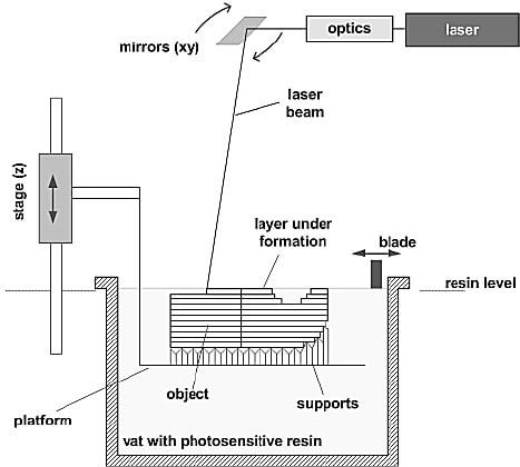
Stereolithography (SL ) was commercially introduced by 3D system Inc. (Valencia, CA ) in the late 1987 based upon a patented process originally developed by Mr. Charles Hull. Since this was the first RP technique, various system are presently available commercially to industries.
Solid Ground Curing
Cubital limited has developed this RP system. In this process, a layer of liquid polymer resin is cured by ultraviolet light. This is accomplished by exposing the layer in a flash or flood manner. The boundary and area for exposure generated by developing a glass Mask plate by electrostatic deposition of black toner by milling to provide a flat support for the next layer. When all layers are complete, the prototype part is washed away to remove the water-soluble wax. Cubital photopolymer resin is completely cured during fabrication of each layer.
Droplet Deposition Manufacturing
Using this technology, the metal droplets can be generated flexibly and controlled precisely. Net-firm manufacturing of components or ingots based on precisely controlled metal droplets is gaining industrial interest due to the promise of improved component quality resulting from rapid solidification processing and the economic benefits associated with a structural component in one integrated operation.
2. Solid Based Rapid Prototyping Techniques
In this category, two RP methods will be discussed:
- Laminated object manufacturing, and
- Fused deposition modeling
Laminated object manufacturing
Laminated object manufacturing is a lesser-known additive manufacturing process that involves successively layering sheets of build material, bonding them with heat and pressure, and then cutting them into the desired shape with a blade or a carbon laser.
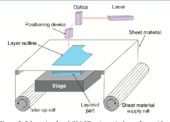
The laminated object manufacturing (LOM ) process from Helisys, Inc. ( Torrance, CA ) uses solid sheet materials, most typically bleached “butcher” paper to create prototype parts. In this process, the LOM machine automatically positions a thin sheet of material from a roll onto an elevator platform.
Fused Deposition Modeling
Fused deposition modeling (FDM) is a technology that uses the melt extrusion method to deposit filaments of thermal plastics in a specific pattern. FDM, like 3DP, has a printhead that can move along X and Y axes above a build platform.
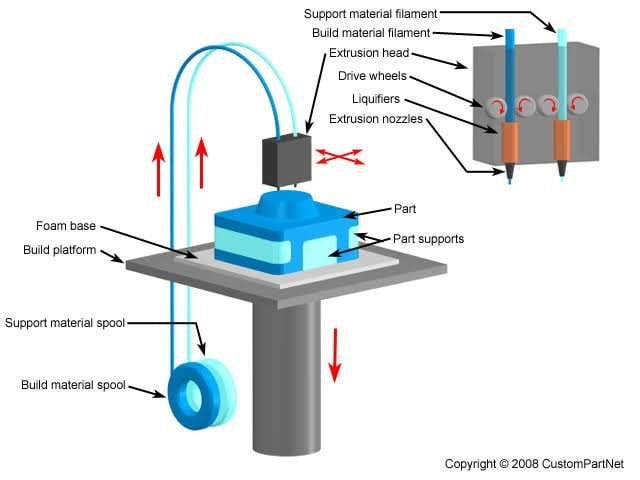
Fused Deposition Modeling ( FDM ) is the name of the technology used by Commercial Rapid Prototyping (RP ) systems from Stratasys, Inc. ( Minneapolis, MN ). The Stratasys systems are primarily targeted for product development terms for use during the conceptual design stage. The system utilizes simple operation. Inert materials and lack of fumes make the FDM process quite compatible with an office environment.
3. Powder Based Rapid Prototyping Technologies
In this categories, three Rapid Prototyping methods will be discussed:
- Selective laser sintering
- Three dimensional printing and
- Laser engineered net shaping
Selective Laser Sintering
The Selective Laser Sintering (SLS ) system from DTM corporation (Austin, Texas ) builds part layer by layer using a laser to bond powdered material into the desired part shape. In this process, a layer of thermoplastic powder is a spread out. Then using a high power laser beam, the portion needed for the model is melted and cooled. A roller then spreads the next layer and the process is repeated.
The uncentered Powder serves the function of supports for overhanging features. Recently, the process has been extended to produce ceramic and metallic parts. The process requires sintering in a furnace for complete bonding. The process is simple. The range of material is broad. The visual limitation is that the parts are porous and are therefore useful for only a specific Applications.
Three Dimensional Printing
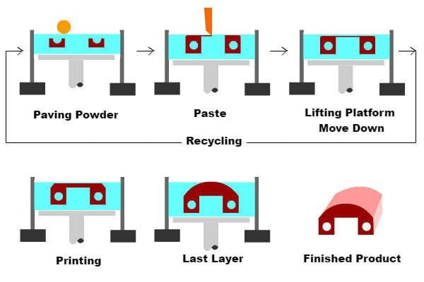
In this process, a three dimensional object is fabricated by selectively applying binder to thin layers of powder, causing particles of powder to stick together. Each layer is formed by generating a thin coating of powder and then applying binder to it with the ink-jet like mechanism. Layers are formed sequentially and adhere to one another to generate the three dimensional object.
Unwanted droplets of binder are skimmed before reaching the powder by electrically changing them at the nozzle and then deflecting them from the stream by applying a potential to the electrodes located below the nozzle. After all later are formed, the unbonded powder is removed and the part is fired in an oven to cure and strengthen.
This process can be used to fabricate parts in a wide variety of materials, including ceramic, metal, metal- ceramic composite and polymers. The limitations is inadequate surface finish and porosity.
Laser engineered Net shaping
The strength of these technologies lies in the ability to fabricate fully dense metal parts with good metallurgical properties at reasonable speeds. A high power laser is used to melt metal powder supplied coaxially to the focus of the laser beam through a deposition head. A variety of materials can be used such as stainless steel, copper, aluminum etc. Of particular interest are reactive materials such as titanium.
Most systems use powder feedstock. Objects fabricated are near net shape, but generally will require finish machining. They are fully dense with good grain structure, and have properties similar to, or even better than the intrinsic materials. Initial applications are concentrated on the fabrication and repair of injection molding tools and the fabrication of large titanium and other exotic metal parts for aerospace applications.
Limitations of Rapid Prototyping
Rapid prototyping systems can not yet produce parts in a wide range of product, at a fast rate. Nevertheless, an increasing number of applications are taking advantage of additive fabrication and now incorporate parts that are directly made by RP processes. Today, typically these requirements are low-volume items with complex geometries used in high value added applications such as medicine or aerospace.
As materials and technologies have improved, and as the capabilities have become more widely understood, direct manufacturing has become a fast growing area in Rapid Prototyping.
To address a wider range of applications sooner, RP is also often used as the starting point for making conventional fabrication processes faster, cheaper and better. Rapid prototyping is used in two ways to accomplish this: Molds may be directly fabricated by an RP system, or RP-generated parts can used as patterns for fabricating a mold through so-called indirect or secondary processes.
Rapid Prototyping Applications
Rapid prototyping is used to model new products at a very fast rate. Jacob has identified the following applications of Rapid Prototyping :
- Visualizations
- Verification
- Iteration
- Optimization
- Fabrication
1. Visualization
In blue prints and CAD models, the visualizers have some difficulties to correctly identifying some of the features of the product. This is true specifically when the product contains blind holes, complex interior passage ways and compound curve surfaces, etc. Rapid prototyping can detect all the features as the prototype of the final product is available for inspection and appropriate decision making.
2. Verification
Manufacturing engineers and mangers can check up the characteristics such as strain, operational temperature fatigue etc. on fully functional prototype. Thus the product can be verified before it goes to a fully manufacturing cycle.
3. Iteration
Once the prototype is made the designer can perform tests on it within the physical limit of the prototype. For example fluid dynamic flow test can be made on a prototype, cured photopolymer material. If a problem is detected during the test the geometry can be modified in the model, a new RP can be built and the same test can be made for its use.
4. Optimization
Design Optimization can improve the situation further. RP Technology allows the design to alter the design without any problem. Having achieved an acceptable design through RP Iteration, the designer has the opportunity to attend to optimize the design by changing various parameters of the product and to test, which is the best one.
5. Fabrication
Once an optimized prototype has been developed by the using any of the methods of RP Technologies, it is important to fabricate a functional test model (FTM). Because this model has not yet been fabricated or tested, it is not known if it will pass the functional test requirements. RP can be used to perform functional test on the FTM. If the test result is satisfactory, tools are pre manufacturing activities start.
I hope you Liked this article on the Rapid prototyping – The complete overview including the definitions, techniques, technologies and applications.
Advantages of Rapid Prototyping
Rapid prototyping has several advantages, such as:
- Reduced design cycle time
- Improved accuracy and quality of the product
- Faster time-to-market
- Reduced risk of errors
- Reduced cost of development
- Improved communication between designers and manufacturers
Disadvantages of Rapid Prototyping
Rapid prototyping also has some disadvantages, such as:
- Limited material options
- Limited size of the model
- Limited resolution and accuracy
- High cost of equipment and maintenance
- Post-processing requirements
What is binder jetting?
Binder jetting uses a binder to selectively bond powdered material layer by layer, creating a solid model. The binder is applied to the powder bed using inkjet printheads, which selectively deposit the binder onto the areas where the model is to be formed. Overall, rapid prototyping is a valuable tool in product development, allowing designers to quickly create and test physical models before finalizing the design. By understanding the various types of rapid prototyping techniques and their advantages and limitations, designers can choose the appropriate technique for their specific project requirements.
Conclusion
Rapid prototyping is a technology that has revolutionized the manufacturing industry by providing a faster and more cost-effective way to create physical models of a product. There are several types and techniques of rapid prototyping, each with its own advantages and disadvantages. Rapid prototyping has several advantages, such as reduced design cycle time and improved accuracy and quality of the product, but it also has some disadvantages, such as limited material options and high cost of equipment and maintenance. Overall, rapid prototyping is a valuable tool for designers and manufacturers to create better products faster and with less risk.
Rapid Prototyping : FAQs
What is the difference between rapid prototyping and 3D printing?
Rapid prototyping is a process that includes several techniques such as 3D printing, while 3D printing is a specific technique of rapid prototyping.
What materials can be used for rapid prototyping?
Materials such as plastic, metal, wood, and paper can be used for rapid prototyping.
How long does it take to create a physical model using rapid prototyping?
The time required to create a physical model using rapid prototyping depends on the complexity of the model and the chosen technique.
What is the advantage of using rapid prototyping in product development?
Rapid prototyping helps reduce the time and cost of product development by allowing designers to quickly create and test physical models before finalizing the design.
Can rapid prototyping be used for mass production?
While rapid prototyping is useful for creating small numbers of physical models, it is not typically used for mass production as it can be time-consuming and expensive. Other manufacturing techniques such as injection molding or CNC machining are more appropriate for mass production.
What are the different types of rapid prototyping techniques?
There are several rapid prototyping techniques available, including stereolithography, selective laser sintering, fused deposition modeling, and binder jetting. Each technique has its own advantages and limitations, and the choice of technique depends on the specific requirements of the project.
How does stereolithography work?
Stereolithography uses a laser to cure a liquid photopolymer resin layer by layer, creating a solid model. The laser traces the cross-section of the model onto the surface of the resin, solidifying it, and repeating the process until the model is complete.
What is selective laser sintering?
Selective laser sintering uses a laser to fuse powdered material layer by layer, creating a solid model. The laser heats the powdered material to just below its melting point, causing it to fuse together and solidify into the desired shape.
How does fused deposition modeling work?
Fused deposition modeling extrudes a thermoplastic material layer by layer, building up the model from the bottom up. The material is extruded through a heated nozzle and deposited onto the build platform, where it cools and solidifies into the desired shape.
What is an example of rapid prototyping model?
An example of a rapid prototyping model is Fused Deposition Modeling (FDM), a process that involves extruding a thermoplastic material through a nozzle to create a physical model layer by layer. Other examples include Stereolithography (SLA), Selective Laser Sintering (SLS), and Binder Jetting.
What is the goal of rapid prototyping?
The goal of rapid prototyping is to quickly and efficiently create physical models of a product to test and refine the design. This allows for faster product development and can help reduce costs associated with traditional manufacturing processes. The use of digital models and rapid prototyping machines enables designers to make changes and iterate on their designs in a shorter time frame, leading to a more efficient and effective design process.
Check Out Other Important Topics
Plant Layout – Types, Objectives, Principles, Advantages
Types of Punches – Uses, Working, Applications, Pictures
Types of Dies – Classification, Uses, Pictures
Types of Rivets – Working & Their Uses [with Images]
Types of Fasteners – Uses & Examples [with Pictures]
| IC Engine | Important PDFs | Boilers | Synergy Maritime Exam | Naval Arch | MEO Class 4 |
| Interview Questions | Difference Between | Types of Pumps | Auxiliary Machines | Types of Valves | Home |

