Steering Gear in Ship Working, Types, Diagram, Regulations

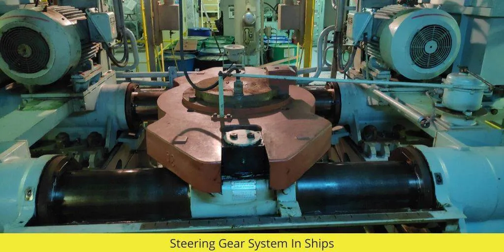
What is Steering Gear ?

Steering gear is the system used on ships to control the direction of the vessel. It allows the ship to turn from port (the left side) to starboard (the right side), or from starboard to port, while it is moving during sailing.

Important Note: The steering gear only works when the ship is in motion. It does not function when the ship is stationary.

Steering Gear In Ship

Capacity

For optimal performance, a steering gear system must have the capacity to rotate the rudder from 35° port to 35° starboard. Additionally, it should be able to transition the rudder from 30° on one side to 35° on the other side within 28 seconds. This ensures quick and efficient maneuvering of the ship.

Limitations and Efficiency of Steering Gear
One important limitation to note is that the steering gear operates effectively only when the ship is in motion. When stationary, the system will not function properly, making it crucial for navigation during active sailing.

Must Read : Fresh Water Generator

Main Parts of Steering Gear

The main components of a ship’s steering gear system are crucial for controlling the rudder and, by extension, the ship’s direction. Here are the key components:

1. Rudder: The rudder is the primary component responsible for changing the ship’s direction. It is mounted at the stern and moves side-to-side to steer the vessel.

2. Steering Gear Motor : This motor powers the entire steering system, providing the necessary force to move the rudder. It can be hydraulic or electro-hydraulic.

3. Hydraulic Pump: In hydraulic systems, the pump generates pressure to actuate the rudder’s movement. It is essential for providing smooth and controlled rudder operations.

4. Control Unit : The control unit is responsible for receiving signals from the bridge (via the steering wheel or autopilot) and converting them into actions for the steering gear.

5. Ram (Actuator) : The ram or actuator converts the hydraulic or mechanical force from the steering gear motor into movement to turn the rudder.

6. Telemotor : The telemotor transmits steering commands from the ship’s bridge to the steering gear unit, using hydraulic or electrical signals.

7. Steering Gear Transmission Linkages : These mechanical linkages connect the control unit to the rudder stock, ensuring precise movement of the rudder as commanded by the bridge.

8. Rudder Stock : The rudder stock is the shaft that connects the rudder to the steering gear. It transmits the movement from the steering gear to the rudder.

9. Hunting Gear : A feedback device that monitors the position of the rudder and ensures it aligns with the helm’s position, helping to correct any deviations automatically.

10. Relief Valve : A safety component that prevents excessive pressure build-up in the hydraulic system, protecting the system from damage.

These components work together to ensure the ship can steer effectively and safely.

Main Components of Steering Gear System

Main Components of Steering Gear System

In the steering system, the steering gear provides a movement of the rudder In response to a signal from the bridge.

3 main parts of steering gear system

a) Control Equipment :- Control equipment convey a signal of desired rudder angle from the steering flat where it is received to activate the power unit and transmission system until the desired angle is reached.

b) Power Unit :- power unit provides the force when required & with immediate effort to move the rudder to the desired angle.

c) Transmission Unit to the Rudder Stock :- Transmission system (steering gear) is the means by which the movement of the rudder is accomplished.

Note :- Control equipment can be hydraulic control equipment ( known as telemotor ) or an electrical electronic control equipment.

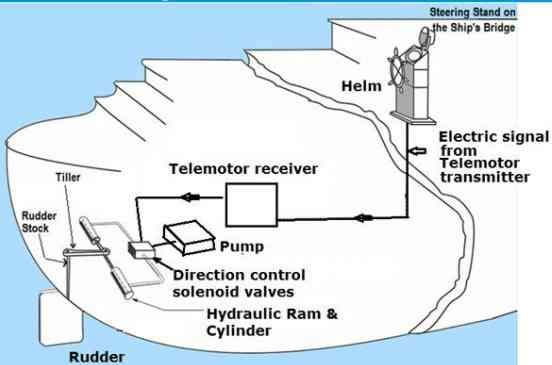
The steering control (Tele-motor transmitter) on the navigation bridge which sends electrical signals to the Tele-motor receiver in the ship’s steering gear room.

This Tele-motor receiver in the steering gear room sends electrical signals to the Direction control solenoid valves.

What are the Types of Steering Gear used on Ship?

1) Electro-hydraulic system

a) Ram type system ( 2 ram or 4 ram)

b) Vane type system

2) All electric system a) Ward Leonard system b) Single motor system

Types of Hydraulic Powered Transmission Unit or Steering Gears

It is of two types :-

a) Ram type ( may be 2 ram or 4 ram )

b) Rotary vane type

Here we will Discuss About Ram Type Steering Gear System

Ram Type Steering Gear System Working

Working

If the oil is pumped into the LHS (port) hydraulic cylinder and drawn from RHS ( starboard) hydraulic cylinder, there will be a left to right sliding movement of the rams. Through the RAM cross head, the tiller arm will move towards starboard and the rudder towards port .

The instant pumping is stooped , movement of tiller arm will stop and rudder will be hydraulically locked in this new position as oil now has no way to leak and is fully blocked within the ram cylinders and vice – versa.

Two Ram Steering Gear Working

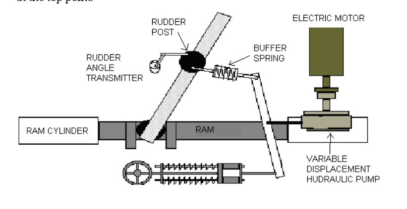
Sketch shows the arrangement of a 2 Ram the steering gear.

Two Ram Steering Gear System

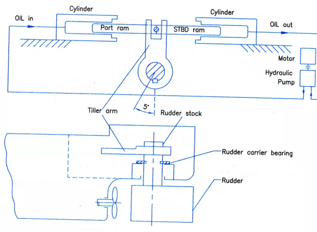
When the steering wheel is turned signal goes to telemotor receiver through the telemotor transmitter which operates the hunting gear.

Hunting gear int urn Moves the variable delivery pump (hele shaw or swash plate type ) operating spindle from neutral position.

Thus pump start pumping to one hydraulic cylinder and from the other hydraulic cylinder, oil is sucked to pump. And the Ram starts moving and this movement is transmitted through the tiller to the rudder stock and rudder.

The movement of rudder cause the hunting gear to move in such a way that once the desired angle of rudder is reached the pumps operating spindle comes back to neutral positions, and no further pumping & rudder remains in desired angular position.

4 Ram Steering Gear Working

Above Diagram shows the arrangement of a four ram steering gear.
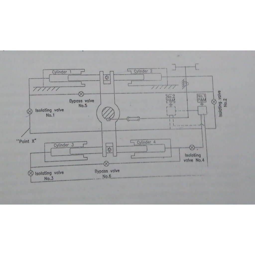
4 Ram Steering Gear System in Ship

Working

As the signal from the telemotor system operates the hunting gear it actuates the variable delivery pumps to pumping position,thus oil flows to two numbers diagonally opposite cylinder ( say 1 and 4 ) from other two cylinder (two and three ) oil is sucked into the pump.

This causes the rudder to turn in clockwise direction. If due to the action of telemotor system hunting gear is moved to other direction then oil will be supplied to cylinder 2&3 and from 1& 4 oil will flow into the pump and thus the rudder turns in anticlockwise directions.

Turning of the rudder will move the hunting gear in such a way that so that once the desired position is reached , pump operating Lever will bring the pump into neutral position and the desired rudder position will be maintained.

Each cylinder is fitted with cylinder isolating valve. There are two bypass valve and relief valve connecting cylinder 1 and 2 & cylinder 3 and 4.

In case of excessive pressure in the cylinder ( which may occur due to shock on the rudder )

The spring loaded bypass valve will open automatically causes the connected cylinder to bypass.

Replenishing tank is provided into the system to make up any loss of Hydraulic oil .

Safety Arrangements in a Steering Gear System on Ship

A) Isolating valve :- isolating valves are provided at each cylinder & Rotary vane number which when closed it will hold the rudder by trapping the oil in the Chambers.Pumps are also equipped with an isolating valves so that the pump can be totally shut off from the circuit and removed for servicing while the steering is continued with the other pumps.


B) Bypass valve:-. Bypass valves are normally closed but can be opened on two cylinder gear to allow for the use of emergency steering.One pair of cylinder can be bypassed on a four cylinders – gears while the other pair of cylinders provide emergency steering at reduced torque.


C) Relief valves :- relief valves are provided between complementary pair of cylinder or Chambers of vane gears. They are set to lift at pressure above the normal maximum.


D) Shock valves are fitted in pipework of the system between cylinders to prevent excessive shock load from the rudder due to heavy seas being transmitted to the hydraulic system.

What are the Safety Devices for Steering System

Safety Devices are

  1. Hunting gear
  2. Buffer spring
  3. Angle adjusting stop (Hand over position limit switch)
  4. Double shock valve
  5. Relief valve
  6. Tank level alarm (oil)
  7. Over load alarm

How does a ship steering gear work ?

The ‘control force’ for turning is triggered off the wheel at the helm, which reaches the steering system. The steering system generates a torsional force at a certain scale, which is then, in turn, transmitted to the steering gear that rotates the steering wheel.

What is Emergency Steering ?

The emergency steering system, as the name suggests, is a system that is used during the failure of the ship’s main steering system.
A situation can occur in which the remote control operation may fail to work and their can be a sudden loss of steering control from the bridge. This can be due to sudden power failure, any electrical fault in the system or the control system which includes faulty tele-motor or servo motor which is used for transferring the signal from bridge to the steering unit.

An emergency steering system is used to control the steering of the ship in such an emergency situation by manually measuring it from inside the steering gear room.

Steering Gear in Ship


Wikipedia

Frequently Asked Questions ( FAQ )

What is the purpose of steering gear?

Its purpose to turn the ship from port to starboard and Vice-versa. Its purpose in car to turn the wheel.

What are the 3 main parts of steering gear system?

The main parts are Transmission , power unit and Control Unit.

What are the 2 types of steering systems?

1.Hydraulic and 2. Electrohydraulic

What is Steering Ram ?

The steering ram, also known as the steering cylinder, is the most important part of a hydraulic steering system. To ensure proper and precise operation, choose an appropriate steering ram for your application.

What is Follow up and Non follow up Steering system ?

Follow up : – This is the standard steering method, which includes steering angle feedback to the helm. This can be operated manually or automatically.
The ship’s heading can be programmed into the autopilot, which can then compare it to the desired heading and adjust the rudder angle accordingly.

Non Follow Up– Normally used only for backup purposes. Each steering gear unit has a single lever; by moving the lever in one direction, the rudder begins to turn; the rudder continues to turn until the lever is released or it reaches the limit of its operation.

What Do You Call Someone who Steers a Ship ?

A helmsman or helm is a person who steers a ship, sailboat, submarine, other type of maritime vessel, or spacecraft.

Why is Steering Test rudder angle 35 Degree to 30 degree ?

It is because the point at which it is reached can be exactly judged as it crosses 30 degree. And As hunting gear puts pump stroke to zero, the rudder movement slows down progressively as it approaches 35 degree.

Duplex Strainer | Duplex Filters – Function & Working

Duplex strainer

A duplex strainer, also known as a twin basket strainer, is a type of filter that is installed in a gas, oil, or water piping system to remove large particles of dirt and debris. In most cases, a duplex strainer system consists of two separate housings for strainer baskets. A valve handle is also included between the two boxes to redirect liquid flow to one strainer while the other is being cleaned.

In some strainers, the valve will operate automatically, and the strainer will perform a self-cleaning method.

These kind of strainers are used in pipeline systems when the flow cannot be stopped. They can filter up to 40 µm depending on the size of their NB. Basket strainers are used in industries where the majority of the pollutants are solids. These strainers, unlike other types of strainers, are very simple to maintain.

Duplex strainer

Duplex Strainer Working Principle

The working principle of a duplex strainer is based on allowing continuous filtration of liquids while providing an option for maintenance or cleaning without interrupting the system. It consists of two filter chambers, each containing a perforated basket or mesh that captures debris and particles from the fluid. During operation, liquid flows into one of the chambers, where the strainer basket filters out unwanted particles, and the cleaned liquid then exits the system.

A key feature of the duplex strainer is the changeover valve, which enables operators to switch the flow from one chamber to the other. When one filter becomes clogged, the flow is diverted to the second, clean chamber, allowing the clogged filter to be cleaned or replaced without stopping the system.

This continuous operation ensures that the system can keep running without downtime. Once maintenance on the clogged filter is completed, the cleaned chamber can be brought back into use. Duplex strainers are commonly employed in applications that require the protection of equipment, such as pumps and valves, from debris while maintaining uninterrupted flow.

How does a Duplex Strainer Work?

A Duplex strainer, or a Basket strainer, is made up of two distinct strainer baskets that are housed together. The suspended solids are trapped in a cleanable basket.
A valve handle is put between the two baskets to restrict the flow of liquid to one strainer while the other is being cleaned. Butterfly valves are used to change the flow direction.


Lube oil system uses duplex filters. Only one filter is used at a time, while the other is kept clean.

What is the purpose of Duplex Strainer?

These strainers or filters are used where the flow of the fluid cannot be stopped. For example in Fuel Lines, Lube Oil lines etc where if the flow is stopped, it can lead to fatal failure of engines and equipments.

Cleaning of Duplex Filter

Filters are cleaned on a regular basis or whenever there is a pressure drop. To clean the filter, flip the filter over to the clean side.

Open the purge cock on the filter you’re using and make sure oil is flowing through it.

Open the filter’s purge cock which is not in use. After the oil has stopped flowing, open the cover and remove the filter element.

When using heavy fuel oil, use caution because it will be quite hot. The filter is made up of notched wire. The size of the notched wire is determined by the micron rate of filtering. It ranges in size from five to 35 microns.

Using kerosene and compressed air, clean the filter element. Replace the filter element and lid, then slowly switch over and expel the air from the filter housing.

How do self cleaning filters work?

Self-cleaning filters clean themselves by utilizing system pressure. The filter’s rigid cylinder screen strains particles from the water source, keeping the material inside.

This buildup can result in a pressure difference between the inlet and the outlet. A flush valve opens when the pressure differential reaches the set control (usually approximately 7psi). This produces a low-pressure flow, which allows the suction nozzles to vacuum the particles out of the filter.

Advantages of Self-Cleaning Filters

Automatic self-cleaning filters have a number of benefits, the most important of which is that they are low-maintenance, making them a great choice for remote sites because they do not require operator participation.

Another significant advantage of industrial self-cleaning filters is that they clean themselves while the system is still in operation. The user saves money, energy, and time as a result of this. They also usually feature a compact form that allows for installation flexibility.

Buy Duplex Strainers

Also Read :

Piston – Construction, Types, Working

Heat Exchanger | Types | Working | Uses

Steering gear safeties

What are Steering Gear Safeties ?

Steering gear safeties are mechanisms integrated into the steering gear system to protect the vessel’s steering mechanism from potential damage, ensure safe operation, and alert the crew to any issues. These safeties are critical for both hydraulic and electrical systems, ensuring the steering gear operates within safe limits.

Categories of Steering Gear Safeties:

  1. Hydraulic Safeties
  2. Electrical Safeties

Hydraulic Safeties:

  1. Level Switch: Monitors the hydraulic oil level in the tank, triggering low-level and low-low-level alarms.
  2. Relief Valve: Prevents overpressure in the hydraulic system by releasing excess pressure.
  3. Manual Bypass Valve: Allows manual override or bypass of the hydraulic system in case of failure.
  4. Low-Pressure Valve: Alerts if hydraulic pressure drops below safe operating levels.
  5. High Lube Oil Temperature Cut-Out: Shuts down the system if lubrication oil temperature exceeds safe limits.
  6. Low-Level Cut-Out: Shuts down the hydraulic system if the oil level falls below a critical point.

Electrical Safeties:

  1. Electrical and Mechanical Stopper for Rudder: Prevents the rudder from moving beyond safe limits.
  2. Electrical Motor Overload Alarm: Warns if the steering motor is drawing excessive current.
  3. Power Failure Alarm: Alerts the crew in case of a loss of power to the steering system.
  4. High Temperature Alarm: Triggers if electrical components overheat.
  5. Self-Starting after Power Failure: Automatically restarts the steering gear after a power outage.
  6. Short-Circuit Trip: Cuts power to the system in the event of a short circuit.
  7. Phase Failure Alarm: Detects loss of one or more phases in a three-phase electrical supply.
  8. 200% Insulation in Motor: Ensures the motor has double insulation for added protection.

Other Safety Devices for the Steering System:

  • Hunting Gear: Used to reduce oscillations in the steering gear system.
  • Buffer Spring: Helps to absorb shock and prevent mechanical damage.
  • Angle Adjusting Stop (Hand Over Position Limit Switch): Limits rudder movement to prevent damage.
  • Double Shock Valve: Provides protection against hydraulic shock in the system.
  • Relief Valve: Prevents overpressure in the hydraulic system.
  • Tank Level Alarm (Oil): Alerts when oil levels in the hydraulic tank drop.
  • Overload Alarm: Warns of excessive load on the steering gear system.

These devices work together to ensure the safe and efficient operation of the steering system, helping prevent malfunctions and protecting the vessel from potential hazards.

Follow me on Twitter

Tappet Clearance Inlet and Exhaust Pdf, Tool, Adjustment

Tappet clearance is a crucial aspect of vehicle engine maintenance that should not be ignored. It refers to the clearance or gap between the camshaft and valve in an engine. It plays a significant role in ensuring optimal engine performance and longevity. Regular tappet clearance adjustment can prevent engine damage, increase fuel efficiency, and reduce engine noise.

Without adequate tappet clearance, there is a risk of valve damage and potential harm to the engine. Therefore, it is necessary to maintain the appropriate clearance to keep the vehicle running smoothly. In this article, we will provide you with a comprehensive guide on tappet clearance, its purpose, and the importance of regular maintenance. We will also discuss how to check and adjust the valve tappet -clearance and the common signs of tappet- clearance issues.

What is Tappet clearance?

Tappet clearance is the small gap between the rocker arm and the top of the valve stem (Yoke).  It is an important factor in determining the timing and duration of valve opening and closing, which affects engine performance and efficiency.

Tappet Clearance

Some Other Definitions are mention below :

It is nothing but a gap between the rocker arms and the point where they rest on the stem of valves. These Both surfaces are flat.

Note :- It is also known as valve lash (in some book ).

Conditions for Tappet clearance?

It can be only adjusted when the valves are closed and the engine is cooled during the compression stroke. It is taken when the inlet and outlet valves are in closed position & engine at the cooled condition at the compression stroke.

When Tappet Clearance of Inlet and exhaust Valve is taken ?

As with any engine maintenance task, checking tappet clearance should be done at particular intervals or when certain conditions arise. To ensure that the engine valve mechanism performs optimally, tappet clearance must be inspected and adjusted according to the following conditions:

  • According to running hours mentioned in the engine manual. Running hours depend on the types of engine. , model or size: Checking tappet clearance after every running is recommended. This interval can vary depending on the make and model of the vehicle, so it’s essential to consult the owner’s manual to determine the right maintenance schedule. Regular inspections can prevent significant damage and expense down the line.
  • Unusual engine noise: Abnormal engine noises, such as clicking or ticking sounds, can indicate that the tappet clearance is not correct. A quick inspection can help diagnose the problem before it becomes more serious.
  • Engine overheating: If the engine overheats frequently, it can cause wear and tear on the engine’s components, including the valve mechanism. In such cases, it’s wise to check the tappet clearance and adjust it if necessary.
  • Low engine compression: Low engine compression can lead to poor acceleration, fuel economy, and other performance issues. It’s essential to check the tappet clearance in such cases as incorrect clearance can cause compression loss.

By keeping an eye out for these conditions and adhering to the set maintenance schedule, you can ensure proper tappet clearance and optimal engine performance.

Tappet Clearance Purpose ?

The purpose of Tappet Clearance is to allow some mechanical expansion and lengthening of the valve stem and push rods when the engine warms up.

The primary function of tappet clearance is to allow for a small expansion gap between the valve stem and pushrods to accommodate the effects of a heated engine.

If this is not done, the valve will not sit properly as the engine heats up. As previously stated, this could eventually result in power loss, engine irregularities, and other issues.

why tappet clearance is required ? Why it is Required ?

The requirement of clearance is answered as, to maintain correct timing ( change in clearance will lead to an early or delayed opening of the inlet or exhaust valves ).

Note :- It needs to be adjusted for proper opening and closing of valves of the diesel engine.

The valve is one of the most critical parts of the engine. It controls the flow of air and fuel into the engine and the exhaust gases out of the engine. The valve opens and closes by the movement of the rocker arm, which is connected to the camshaft. Tappet clearance affects the valve operation by controlling the timing and duration of valve opening and closing.

  • Timing: Tappet clearance plays a crucial role in determining the timing of valve opening and closing. The correct tappet clearance ensures that the valve opens and closes at the right time, allowing the engine to operate efficiently.
  • Duration: The duration of the valve opening and closing is also affected by tappet clearance. The appropriate clearance ensures that the valve stays open for the right amount of time, allowing enough air and fuel to enter the engine.

Therefore, maintaining the correct tappet clearance is essential for optimal engine performance and longevity. It helps ensure that the engine runs smoothly, efficiently, and with minimal wear and tear.

In simple, it is required to maintain proper timing of opening and closing of valve without any delay or early inlet opening.

Effect of Incorrect Tappet Clearance of Exhaust Valve

Having incorrect tappet clearance in a vehicle’s engine can lead to a host of issues affecting the overall performance and longevity of the engine. Let’s take a look at some of the effects that can result from improper tappet clearance:

  • Valve Damage: Insufficient tappet clearance can cause the valves to remain partially open, leading to overheating and ultimately damaging the valves.
  • Decreased Engine Performance: Incorrect tappet clearance can reduce engine power and torque output, resulting in poorer overall performance.
  • Increased Fuel Consumption: When tappet clearance is too tight, the engine has to work harder to operate, resulting in increased fuel consumption and higher expenses for the vehicle owner.
  • Noisy Engine: When tappet clearance is too loose, it can cause the engine to produce a knocking or ticking sound, which can be annoying and an indication of a more severe underlying problem.

It is essential to maintain the correct tappet clearance to avoid these issues and ensure that your vehicle’s engine operates smoothly and efficiently for as long as possible.

What Will Happen if Tappet Clearance Less :-

If the clearance decreases– The valve will open early and close late.

The valve will open sooner and close later if the clearance decreases. This is due to the rocker arm remaining connected to the valve for an extended period of time. We get a larger contact area between the valve stem and rocker arm with less clearance. As a result, the rocker arm pushes the valve down for a longer period of time, keeping the valve open for longer.

  1. Valve will open early and close lately.
  2. Air induced in combustion chamber for combustion through an inlet valve may leak out. So, less air will be available for combustion.
  3. Power of the engine will be reduced.
  4. Fuel consumption by engine will increase, and engine may become unbalanced and the exhaust temperature will be very high.
  5. The valve may remain open, in worst conditions, resulting in loss of compression pressure of the engine, burning of the exhaust valve and increase in turbocharger fouling.

What will happen if Tappet clearance is more :-

If the clearance increases– The valve will open late and close early.

If the clearance increases, the valve will open slowly and close quickly. Because there is more clearance, the contact area between the valve stem and rocker arm is smaller. As a result, the valve remains open for a shorter period of time but closed for a longer period of time (which explains the delayed opening).

  1. The valve will open lately and close early.
  2. It reduces the maximum lift of the valve.
  3. Less heat energy to the turbocharger of engine, cause reduction in the scavenge air and hence power decrease.
  4. There is no proper removal of the exhaust gas.
  5. Hammering of the v/v stem cause damage to the valve stem.
  6. It causes noise and eventually damage the working surface.

How to check Tappet clearance ?

Tappet Clearance is checked by using feeler gauge by putting in between the space of rocker arm and the Space where valve stem sit.

Checking the tappet clearance is a crucial part of engine maintenance. It ensures that the valve is opening and closing at the correct time, and the engine is running smoothly. Here is a step-by-step guide on how to check the tappet clearance:

  1. First, make sure the engine is cool before checking the tappet clearance. This will prevent any damage to the components.
  2. Locate the valve cover and remove it from the engine.
  3. Locate the camshaft, which is responsible for opening and closing the valves, and the rocker arm, which pushes on the valve stem to open and close the valve.
  4. Identify the valve that needs to be checked and find the corresponding rocker arm. Use a wrench to loosen the lock nut on the rocker arm.
  5. Insert a feeler gauge between the rocker arm and the valve stem. The feeler gauge should be a tight fit but not too tight that it cannot be inserted. Measure the clearance by noting the thickness of the feeler gauge.
  6. If the clearance is too tight or too loose, adjust it by tightening or loosening the lock nut on the rocker arm. Recheck the clearance to ensure it is within the manufacturer’s recommended specifications.
  7. Repeat the process for each valve in the engine.
  8. Once all the valves have been checked, replace the valve cover and start the engine. Listen for any abnormal noises or vibrations. If everything sounds normal, you have successfully checked the tappet clearance!

Regularly checking the tappet clearance can prevent issues such as valve damage and poor engine performance. It is recommended to check the tappet clearance every 10,000 miles or as specified by the manufacturer.

How to Know Which Unit is at TDC?

To check clearance, first sure that the unit you are going to check should be in Top Dead Centre ( TDC ).

The position of piston is At TDC checked by

  • The flywheel marking 
  • The fuel pump mark 
  • The checking the camshaft fuel 
  • The valve cam position.

If it is not at TDC then we use turning gear to make that unit at TDC. ( Note :- During turning make sure that indicator cock is open ).

Usually, there are 6-8 units in four stroke engines. So at the same time, the flywheel will show two units at TDC.

To make sure that particular unit is on the compression stroke and not at the power stroke, you can turn the push rods of both units by hands to check.

The one with free push rods is the one which is at compression stroke and the one with tight push rods is at power stroke.

So avoid the one which is at power stroke.

Now you need good filler gauges of different thickness.

Now gently try to push these filler gauges between the clearance of valve and rocker arm.

You may have to try different thickness. Just check in the manufacturer manual as for how much standard clearance should be.

Now you know that your clearance is less or more

How to Adjust Valve Tappet clearance / Adjustment Procedure

Prepare the following tools for Checking and Adjusting Tappet clearance of Valve :-

Feeler gauge of different thicknesses.

Tappet clearance inlet and exhaust valve
Valve head clearance adjusting the procedure

Adjusting the valve tappet clearance requires precision and careful attention. Here are the steps to follow:

  1. Start by removing the valve cover from the engine. This will expose the valves and valve springs.
  2. Rotate the engine until the camshaft lobe for the valve you wish to adjust is facing upwards.
  3. Insert a feeler gauge between the valve stem and the rocker arm. You should feel a slight drag when sliding the gauge back and forth.
  4. If the clearance needs adjustment, use an appropriate wrench to loosen the lock nut on the rocker arm and turn the adjustment screw until you achieve the desired clearance. Typically, the clearance specs can be found in the vehicle owner’s manual.
  5. Once the clearance is set, hold the adjustment screw in place and tighten the lock nut to secure the adjustment. Double-check the clearance with the feeler gauge to ensure it matches the desired specification.
  6. Repeat these steps for all the valves you need to adjust.
  7. Once you finish the adjustment, replace the valve cover and all other components you removed earlier.

Remember, precise measurements and adjustments are essential for optimal engine performance. If you are unsure or lack experience, it is best to consult a professional mechanic to perform tappet clearance adjustments.

Note:- When you move filler gauges while adjusting for particular clearance, you should be able to slide it smoothly (not too tight and not too loose ).

Importance of Regular Tappet Clearance Maintenance

Maintaining the proper tappet clearance is essential for the optimal performance and longevity of a vehicle’s engine. Regular maintenance of the tappet clearance should be a part of every vehicle’s maintenance schedule. Neglecting this maintenance can lead to numerous issues, such as decreased engine performance and fuel efficiency, increased engine noise, and in severe cases, valve damage or engine failure.

By incorporating tappet clearance maintenance into your regular vehicle maintenance routine, you can prevent these issues and ensure your engine runs smoothly. Periodic tappet clearance adjustments and inspections can help to optimize fuel efficiency, reduce engine noise, and extend your engine’s lifespan. Additionally, regular maintenance can save you money in the long run by preventing costly repairs due to engine damage resulting from neglected maintenance.

Make sure to consult your vehicle’s owner manual for the recommended tappet clearance maintenance schedule. Regular maintenance will keep your engine running smoothly, protect your investment, and provide a more enjoyable driving experience.

Common Signs of Tappet Clearance Issues

Regular maintenance of tappet clearance is crucial for optimal engine performance. Failure to maintain the correct clearance can lead to various engine problems. Here are some common signs that may indicate tappet clearance issues:

  • Excessively loud or unusual engine noises, especially when accelerating or idling
  • Inconsistent or rough engine performance, including misfires or hesitation
  • Decreased fuel efficiency
  • Increased engine vibrations or shaking

If you observe any of these signs, it is important to check the tappet clearance as soon as possible. Ignoring these symptoms can lead to more severe engine damage and costly repairs. Regular inspection and adjustment of tappet clearance can prevent these issues from occurring in the first place, ensuring smooth engine operation and prolonged engine life.

Tools and Equipment for Tappet Clearance Adjustment

Adjusting the tappet clearance in a vehicle’s engine requires specific tools and equipment to ensure accurate measurements and adjustments are made. Here are some of the essential items needed:

  • Feeler Gauges: These are used to measure the tappet clearance accurately. They come in different thicknesses, depending on the clearance required for a particular engine.
  • Wrenches: Different types of wrenches, such as a socket wrench or an adjustable wrench, may be needed to access and adjust the tappets.
  • Screwdriver: A flat-head screwdriver may be necessary to adjust the tappets, depending on the engine’s design.
  • Valve Cover Gasket: The valve cover gasket must be removed to access the tappets, and a new gasket is essential when reassembling the engine.
  • Shop Towels: It is crucial to keep the engine clean during the adjustment process. Shop towels can be used to wipe any excess oil or debris that may be present.

When performing tappet clearance adjustment, it is essential to follow the manufacturer’s instructions and guidelines carefully. It is also important to take necessary safety precautions, such as wearing gloves and protective eyewear.

Overall, having the right tools and equipment for tappet clearance adjustment is crucial in maintaining a vehicle’s engine performance and longevity. Regular maintenance and adjustments can prevent costly repairs and ensure optimal engine efficiency.

Tappet Clearance Tool

The valve tappet clearance is measured by

A. Vernier Calliper

B. Feeler gauge

C. Screw Pitch Gauge

D. Engineering Scale

Ans :- B. Feeler gauge

what is Tappet clearance

Tappet clearance refers to the small gap or space between the engine valve and the tappet, which is a component that helps control the valve operation. It is an essential adjustment that ensures smooth and efficient engine performance.

How much is tappet clearance?

It’s value is such that does not affect the the engine performance. The clearance taken is typically between 0.2mm and 0.6mm, depending on the inlet and exhaust valves and engine manufacturer.

Why is tappet clearance important?

Tappet clearance is necessary to prevent valve damage, optimize fuel efficiency, and reduce engine noise. Incorrect tappet clearance can lead to various engine problems, which can be costly to repair.

What is the purpose of tappet clearance?

The purpose of tappet clearance is to control the timing and duration of valve opening and closing. It allows for proper fuel combustion, optimal power delivery, and helps prevent valve damage. Maintaining the correct clearance ensures efficient engine operation and prolongs the engine’s lifespan.

Why is tappet clearance necessary?

Tappet clearance is necessary for several reasons. It helps prevent valve damage by ensuring the valve closes completely and does not contact the piston. Correct clearance also optimizes fuel efficiency by promoting proper combustion. Additionally, it reduces engine noise by preventing valve striking and improves overall engine performance.

When should tappet clearance be checked?

Tappet clearance should be checked under specific conditions or situations. It is recommended to check it during routine engine maintenance, after a significant change in engine temperature, if abnormal engine noise is detected, or after certain running hours. Checking tappet clearance regularly helps identify any necessary adjustments.

What are the effects of incorrect tappet clearance?

Incorrect tappet clearance can lead to various issues. If the clearance is too tight, the valve may not fully close, resulting in poor compression and power loss. On the other hand, too much clearance can cause noisy valve operation, reduced engine performance, and increased fuel consumption. It is crucial to maintain the correct clearance for optimal engine function.

How do I check tappet clearance?

To check tappet clearance, you will need a feeler gauge and a service manual for your specific vehicle. Start by removing the valve cover, locate the tappets and valves, and follow the manual’s instructions to measure the clearance using the appropriate gauge. It is important to perform this task with the engine at the correct temperature and in the recommended sequence outlined in the manual.

How do I adjust valve tappet clearance?

Adjusting valve tappet clearance requires precision and following the manufacturer’s guidelines. Typically, it involves loosening the locknut and using a wrench or screwdriver to adjust the clearance to the recommended specification. After adjustment, tighten the locknut to secure the setting. It is crucial to recheck the clearance after completing the adjustment.

What are the common signs of tappet clearance issues?

Common signs of tappet clearance issues include excessive engine noise, ticking or clicking sounds, decreased power, rough idling, and poor fuel economy. If you notice any of these symptoms, it is advisable to have your tappet clearance checked and adjusted if necessary to avoid further engine complications.

What tools and equipment are needed for tappet clearance adjustment?

To adjust tappet clearance, you will typically need a feeler gauge, a wrench or screwdriver for locknut adjustment, and a service manual specific to your vehicle. It is also recommended to have a clean workspace, gloves, and safety glasses for protection during the adjustment process.

Check Out Other Important Topics

IC EngineImportant PDFsBoilersSynergy Maritime ExamNaval ArchMEO Class 4
Interview QuestionsDifference BetweenTypes of PumpsAuxiliary MachinesTypes of ValvesHome

Also Read : Bearing Temperature Detector

Wikipedia

Boiler gauge glass blow through procedure : Easy Step

Boiler Gauge Glass Blow Through Procedure : Blow through of Boiler Gauge Glass is Done to ensure accurate reading of the water level in the boiler and to remove any debris, sediment, or scale that may have accumulated in the gauge glass and its connections.

Boiler Gauge Glass Blow Through Procedure

Boiler gauge glass blow through procedure Step by Step

Step-by-Step Instructions:

  1. Isolate the Steam Connection: Close the steam valve to prevent steam from entering the gauge glass.
  2. Isolate the Water Connection: Close the water valve to prevent water from entering the gauge glass.
  3. Drain the Gauge Glass: Open the drain cock located at the bottom of the gauge glass to allow the contents to drain completely.
  4. Wait for Drainage: Allow the gauge glass to drain completely before proceeding.
  5. Clear the Steam Connection: Open the steam valve to allow steam to flow through the connection and clear any debris or condensate.
  6. Close the Steam Connection: Close the steam valve to prevent further steam flow.
  7. Clear the Water Connection: Open the water valve to allow water to flow through the connection and clear any debris or sediment.
  8. Wait for Complete Drainage: Allow the water connection to drain completely before proceeding.
  9. Close the Drain Cock: Close the drain cock to prevent further drainage.
  10. Refill the Gauge Glass: Open the water valve to allow water to refill the gauge glass.
  11. Open Steam Valve : Open the steam valve to check the water level in the boiler, ensuring it is within the recommended range.

Note: This procedure should be performed daily to ensure the accuracy and reliability of the boiler’s water level indication.

Suggested Reading : Boiler Mountings

procedure of Boiler Gauge Glass Blow Through in Table form

StepProcedure
1.Isolate the Steam Connection
– Close the steam valve to prevent steam from entering the gauge glass.
2.Isolate the Water Connection
– Close the water valve to prevent water from entering the gauge glass.
3.Drain the Gauge Glass
– Open the drain cock located at the bottom of the gauge glass to allow the contents to drain completely.
4.Wait for Drainage
– Allow the gauge glass to drain completely before proceeding.
5.Clear the Steam Connection
– Open the steam valve to allow steam to flow through the connection and clear any debris or condensate.
6.Close the Steam Connection
– Close the steam valve to prevent further steam flow.
7.Clear the Water Connection
– Open the water valve to allow water to flow through the connection and clear any debris or sediment.
8.Wait for Complete Drainage
– Allow the water connection to drain completely before proceeding.
9.Close the Drain Cock
– Close the drain cock to prevent further drainage.
10.Refill the Gauge Glass
– Open the water valve to allow water to refill the gauge glass.
11.Verify Water Level
– Open the steam valve to check the water level in the boiler, ensuring it is within the recommended range.

Note: This procedure should be performed daily to ensure the accuracy and reliability of the boiler’s water level indication. Each step ensures proper isolation, draining, clearing, and verification of the gauge glass, maintaining operational safety and efficiency.

purpose of Boiler gauge Glass

The purpose of this procedure is to:

  1. To ensure the accuracy and reliability of the boiler’s water level indication.
  2. Remove any debris, sediment, or scale that may have accumulated in the gauge glass and its connections.
  3. Prevent any potential damage to the gauge glass or boiler due to clogging or corrosion.
  4. Maintain the overall safety and efficiency of the boiler operation.

Why need to blow down the boiler water ?

  • Boiler blow down is made to reduce the density of salt and to remove the dissolved and suspended solids, also the floating solid impurities in the boiler system.
  • If there are not removed from the boiler water system, foaming, priming, corrosion will occur in the boiler steam space and feed water system.

Wikipedia

Catalytic Converter – Diagram, Working, Function & Types

what is catalytic converter

A catalytic converter is a device used in the exhaust system of internal combustion engines, primarily in vehicles, to reduce the harmful emissions produced during the combustion process. It works by facilitating chemical reactions that convert pollutants and harmful gases, such as nitrogen oxides (NOx), carbon monoxide (CO), and unburned hydrocarbons, into less harmful substances like nitrogen, carbon dioxide, and water vapor.

The catalytic converter contains a catalyst, typically made of precious metals like platinum, palladium, and rhodium, that acts as a facilitator for these chemical reactions. The exhaust gases flow through a honeycomb-like structure coated with the catalyst material. As the gases pass over the catalyst, the chemical reactions occur, transforming the pollutants into less harmful compounds.

The catalytic converter plays a crucial role in reducing air pollution and meeting emissions standards set by regulatory authorities. It has become a standard component in most vehicles worldwide, contributing to improved air quality and reduced environmental impact from vehicle emissions.

Catalytic Converter Diagram

Construction of catalytic converter

A catalytic converter consists of several key components designed to facilitate the chemical reactions that convert harmful exhaust gases into less harmful substances. The construction of a typical catalytic converter involves the following main parts:

  1. Casing: The outer shell of the catalytic converter is usually made of stainless steel or another heat-resistant material. It provides protection to the internal components and ensures that the high temperatures generated during the catalytic reactions are contained within the unit.
  2. Catalyst Support: Inside the casing, there is a substrate or support material that holds the catalyst. This substrate is often a ceramic or metallic honeycomb structure with a large surface area. The honeycomb design provides ample contact area for the exhaust gases to interact with the catalyst.
  3. Catalyst Coating: The catalyst, composed of precious metals like platinum, palladium, and rhodium, is applied as a thin washcoat onto the substrate. These metals act as the catalysts for the chemical reactions that occur within the converter. The washcoat enhances the surface area available for reactions to take place.
  4. Oxygen Sensors: Modern catalytic converters often have oxygen sensors positioned before and after the converter. These sensors monitor the oxygen levels in the exhaust gases, providing feedback to the engine control unit (ECU) to optimize the air-fuel mixture for efficient catalytic conversion.
  5. Heat Shield: Catalytic converters generate substantial heat during their operation. A heat shield made of insulating materials is often placed around the converter to prevent excessive heat from affecting surrounding components and to protect against potential heat-related damage.

The process of catalytic conversion involves several chemical reactions:

  • Oxidation of CO: Carbon monoxide reacts with oxygen to form carbon dioxide.
  • Reduction of NOx: Nitrogen oxides are reduced to nitrogen and oxygen.
  • Oxidation of HC: Unburned hydrocarbons are oxidized into carbon dioxide and water.

These reactions occur on the surface of the catalyst when exhaust gases pass through the substrate. The catalyst provides a surface where the reactions can take place at lower temperatures than would otherwise be required.

Overall, the construction of a catalytic converter is carefully designed to maximize the efficiency of these chemical reactions, thereby reducing the emission of harmful pollutants from the vehicle’s exhaust gases.

Catalytic Converter in Car Diagram

how does catalytic converter works

A catalytic converter works by facilitating chemical reactions that transform harmful pollutants produced during the combustion of fuel into less harmful substances. It is a key component of a vehicle’s exhaust system and plays a critical role in reducing emissions and improving air quality. Here’s how a catalytic converter works:

  1. Exhaust Gas Flow: The process begins with the flow of exhaust gases from the engine into the catalytic converter through the exhaust pipe.
  2. Catalyst Activation: Inside the catalytic converter, there are catalysts made of precious metals like platinum, palladium, and rhodium. These catalysts are coated onto a substrate, often a ceramic or metallic honeycomb structure. The catalysts are specifically designed to promote chemical reactions that occur at lower temperatures than would normally be required.
  3. Oxidation Reactions: As exhaust gases pass through the catalytic converter, they come into contact with the catalysts. In the case of carbon monoxide (CO) and unburned hydrocarbons (HC), the catalysts initiate oxidation reactions. Oxygen from the exhaust combines with these pollutants to form carbon dioxide (CO2) and water (H2O): CO + ½O₂ → CO₂
    HC + O₂ → CO₂ + H₂O
  4. Reduction Reactions: Nitrogen oxides (NOx) are targeted through reduction reactions. A different catalyst, often rhodium, promotes the reduction of nitrogen oxides using unburned hydrocarbons present in the exhaust gases. The result is the conversion of nitrogen oxides into nitrogen (N2) and oxygen (O2): NOx + HC → N2 + CO2 + H2O
  5. Conversion of Pollutants: Through these oxidation and reduction reactions, the harmful pollutants—carbon monoxide, unburned hydrocarbons, and nitrogen oxides—are converted into less harmful substances—carbon dioxide, water, and nitrogen. These products are then expelled from the catalytic converter as exhaust gases.
  6. Temperature Management: Catalytic converters require a certain operating temperature range to function efficiently. Modern vehicles are equipped with oxygen sensors that monitor the oxygen levels in the exhaust gases. The engine control unit (ECU) uses this information to adjust the air-fuel mixture to maintain the optimal temperature for catalytic converter operation.

In summary, a catalytic converter works by utilizing catalysts to promote oxidation and reduction reactions that convert harmful pollutants into less harmful compounds. This technology significantly reduces the environmental impact of vehicle emissions, contributing to cleaner air and improved air quality.

Types of Catalytic Converters

Certainly, let’s delve into more detail about two-way and three-way catalytic converters:

1. Two-Way Catalytic Converter:

A two-way catalytic converter is a type of emissions control device used in internal combustion engines, primarily gasoline-powered vehicles. It’s called “two-way” because it focuses on targeting two main pollutants—carbon monoxide (CO) and hydrocarbons (HC).

Working Principle:

The primary function of a two-way catalytic converter is to facilitate oxidation reactions that convert carbon monoxide and hydrocarbons into less harmful compounds. It accomplishes this using a catalyst, typically composed of platinum and palladium, which is coated onto a ceramic or metallic substrate. The substrate is often designed in a honeycomb structure to maximize the surface area available for reactions.

When exhaust gases pass through the catalytic converter, they come into contact with the catalyst. The following reactions occur:

  1. Oxidation of Carbon Monoxide (CO):
    CO + ½O₂ → CO₂ Carbon monoxide (CO) reacts with oxygen (O₂) to form carbon dioxide (CO₂), a less harmful greenhouse gas. The platinum and palladium catalyst facilitates this oxidation reaction, promoting the conversion of CO to CO₂.
  2. Oxidation of Hydrocarbons (HC):
    HC + O₂ → CO₂ + H₂O Unburned hydrocarbons (HC) in the exhaust gases also undergo oxidation when they react with oxygen, resulting in the formation of carbon dioxide (CO₂) and water (H₂O).
Catalytic Converter

Limitations:

Two-way catalytic converters are effective in reducing CO and HC emissions but do not directly target nitrogen oxides (NOx). They are not as efficient as three-way converters in addressing the full range of pollutants emitted by internal combustion engines. This is why two-way converters are more commonly found in older gasoline-powered vehicles where emission standards were less stringent.

2. Three-Way Catalytic Converter:

A three-way catalytic converter is a more advanced emissions control device widely used in modern gasoline-powered vehicles. It is called “three-way” because it simultaneously addresses three main pollutants—carbon monoxide (CO), hydrocarbons (HC), and nitrogen oxides (NOx).

Working Principle:

A three-way catalytic converter employs a combination of oxidation and reduction reactions to convert the three target pollutants into less harmful compounds. It contains multiple catalysts, typically made of platinum, palladium, and rhodium, which are strategically coated onto the substrate.

  1. Oxidation of CO and HC: The platinum and palladium catalysts promote the oxidation of carbon monoxide (CO) and hydrocarbons (HC) into carbon dioxide (CO₂) and water (H₂O), as explained in the two-way converter section.
  2. Reduction of NOx: The rhodium catalyst facilitates the reduction of nitrogen oxides (NOx) by promoting a chemical reaction with the unburned hydrocarbons present in the exhaust gases. This reaction converts nitrogen oxides into nitrogen (N₂) and oxygen (O₂): NOx + HC → N₂ + CO₂ + H₂O

Advantages:

Three-way catalytic converters are highly effective in reducing all three main pollutants—CO, HC, and NOx—in gasoline-powered vehicles. Their ability to simultaneously address these pollutants makes them a crucial component for meeting stringent emissions standards and ensuring cleaner air quality.

In summary, while both two-way and three-way catalytic converters play significant roles in reducing emissions, three-way converters offer a more comprehensive solution by addressing a broader range of pollutants. As emission standards have become more stringent, three-way catalytic converters have become the norm in modern gasoline-powered vehicles due to their efficiency in meeting regulatory requirements and improving air quality.

function of catalytic converter

The primary function of a catalytic converter is to reduce the harmful pollutants and toxic gases produced during the combustion process in internal combustion engines. It achieves this by facilitating chemical reactions that convert these pollutants into less harmful substances before they are released into the atmosphere. The catalytic converter plays a crucial role in improving air quality, reducing environmental impact, and ensuring compliance with emissions regulations. Here’s how it works:

  1. Oxidation of Carbon Monoxide (CO): Carbon monoxide is a poisonous gas produced by incomplete combustion. The catalytic converter contains catalysts, usually made of platinum and palladium, that promote the oxidation of carbon monoxide into carbon dioxide: CO + ½O₂ → CO₂
  2. Oxidation of Hydrocarbons (HC): Unburned hydrocarbons are released into the exhaust gases when fuel isn’t fully combusted. The catalysts in the converter promote the oxidation of hydrocarbons into carbon dioxide and water: HC + O₂ → CO₂ + H₂O
  3. Reduction of Nitrogen Oxides (NOx): Nitrogen oxides are pollutants that contribute to smog and acid rain. The catalytic converter uses a different catalyst, often made of rhodium, to facilitate reduction reactions that convert nitrogen oxides into nitrogen and oxygen: NOx + HC → N₂ + CO₂ + H₂O

The catalytic converter operates within a specific temperature range. It requires heat to activate the catalysts and initiate the chemical reactions. This is why modern vehicles are equipped with oxygen sensors that monitor the exhaust gases and provide feedback to the engine control unit (ECU). The ECU adjusts the air-fuel mixture to maintain the optimal conditions for catalytic converter operation.

In summary, the catalytic converter’s function is to transform harmful carbon monoxide, hydrocarbons, and nitrogen oxides into carbon dioxide, water, and nitrogen, respectively, through oxidation and reduction reactions. This technology significantly reduces the negative impact of vehicle emissions on both the environment and human health.

Signs of Catalytic Converter Issues

Detecting catalytic converter issues early is crucial for maintaining the performance and emissions control of your vehicle. Here are some signs to watch for that might indicate problems with your catalytic converter:

  1. Check Engine Light: A consistently illuminated check engine light on your dashboard is often the first sign of catalytic converter issues. The vehicle’s onboard diagnostics system detects irregularities in emissions and alerts you through the warning light.
  2. Reduced Engine Performance: If you notice a decrease in engine power, sluggish acceleration, or poor fuel efficiency, it could indicate a partially clogged or malfunctioning catalytic converter. Restricted exhaust flow can impact engine performance.
  3. Rattling or Rumbling Noises: A damaged or failing catalytic converter might produce rattling or rumbling noises, especially when the vehicle is idling or when you tap the converter with a rubber mallet. This indicates that the internal substrate might be broken or loose.
  4. Strong Sulphur Smell: A failing catalytic converter may emit a strong odor of rotten eggs due to sulfur compounds in the exhaust not being properly converted. This smell can be an indicator of incomplete catalytic conversion.
  5. Excessive Heat: If the catalytic converter is not functioning correctly, it might produce excessive heat, causing the undercarriage or floor of the vehicle to become unusually hot. This can potentially lead to other components being damaged.
  6. Failed Emissions Test: During vehicle inspections, if your car fails an emissions test due to high levels of CO, HC, or NOx in the exhaust, it could be a sign of a failing catalytic converter.
  7. Poor Fuel Efficiency: A failing catalytic converter can lead to inefficient combustion and reduced fuel efficiency. If you notice a sudden decrease in miles per gallon (MPG), it’s worth investigating the converter.
  8. Stalling or Rough Idling: A clogged or malfunctioning catalytic converter might cause the engine to stall or have rough idling, as the exhaust gases are not flowing smoothly.
  9. Misfires: Misfiring cylinders can lead to unburned fuel entering the exhaust system, potentially damaging the catalytic converter over time.
  10. Excessive Exhaust Smoke: If you observe blue or black smoke coming from your exhaust pipe, it could be a sign of oil or fuel burning in the exhaust due to an issue with the converter.

If you experience any of these signs, it’s advisable to have your vehicle inspected by a qualified mechanic. Ignoring catalytic converter problems can lead to worsened performance, increased emissions, and potential damage to other engine components. Addressing issues early can help prevent more expensive repairs and ensure your vehicle continues to run efficiently and cleanly.

Catalytic Converter Working Diagram

application of catalytic converter

Catalytic converters are widely used in various industries, primarily in the automotive sector, to reduce the emission of harmful pollutants from internal combustion engines. Here are some of the key applications of catalytic converters:

  1. Automotive Industry: The most common application of catalytic converters is in automobiles, both gasoline-powered and diesel-powered vehicles. They are integrated into the exhaust systems to reduce the emission of pollutants such as carbon monoxide (CO), nitrogen oxides (NOx), and unburned hydrocarbons (HC). This helps vehicles comply with emission regulations and contribute to cleaner air quality.
  2. Motorcycles and Scooters: Similar to automobiles, catalytic converters are also used in motorcycles and scooters to control exhaust emissions and minimize the environmental impact of two-wheeled vehicles.
  3. Heavy-Duty Vehicles: Catalytic converters are employed in trucks, buses, and other heavy-duty vehicles to address their significant emission levels. These converters play a crucial role in reducing the release of pollutants into the atmosphere.
  4. Industrial Applications: Catalytic converters find use in various industrial applications where internal combustion engines are employed, such as power generators and industrial machinery. These converters help mitigate emissions and ensure compliance with environmental regulations.
  5. Stationary Engines: Engines used for stationary applications, such as backup generators or industrial machinery, can be equipped with catalytic converters to reduce emissions and adhere to emission standards.
  6. Agricultural Equipment: Farming equipment, such as tractors and harvesters, can incorporate catalytic converters to minimize emissions and promote environmental sustainability in agriculture.
  7. Construction Machinery: Heavy machinery used in construction and infrastructure projects can be fitted with catalytic converters to decrease emissions and enhance air quality in construction sites.
  8. Marine Engines: Some marine vessels utilize catalytic converters to control exhaust emissions and reduce the impact of shipping on marine ecosystems.
  9. Aerospace: While not as common, catalytic converters have been considered for use in aviation to address emissions from aircraft engines, contributing to efforts to reduce the environmental footprint of air travel.
  10. Power Plants: In certain cases, catalytic converters can be employed in power plants to reduce emissions from fossil fuel combustion and enhance air quality in the surrounding areas.

The widespread adoption of catalytic converters across these various applications underscores their importance in mitigating the environmental impact of combustion processes. By facilitating the conversion of harmful pollutants into less harmful substances, catalytic converters play a vital role in promoting cleaner air and a healthier environment.

advantages of catalytic converter

Catalytic converters offer several important advantages, primarily related to their ability to significantly reduce harmful emissions from internal combustion engines and industrial processes. Here are some key advantages of catalytic converters:

  1. Emission Reduction: The primary advantage of catalytic converters is their ability to effectively reduce emissions of harmful pollutants, such as nitrogen oxides (NOx), carbon monoxide (CO), and unburned hydrocarbons (HC), from vehicles and industrial sources. This helps improve air quality and reduces the negative health and environmental impacts of these pollutants.
  2. Environmental Protection: Catalytic converters play a vital role in protecting the environment by helping to minimize the release of pollutants that contribute to smog, acid rain, and greenhouse gas emissions. This contributes to the overall well-being of ecosystems and human populations.
  3. Regulatory Compliance: Catalytic converters enable vehicles and industrial processes to meet stringent emissions regulations set by governments and environmental agencies. Compliance with these regulations is essential to avoid fines, penalties, and other legal consequences.
  4. Health Benefits: By reducing the emission of toxic gases and pollutants, catalytic converters contribute to improved public health. Lower levels of pollutants in the air help reduce respiratory illnesses, cardiovascular diseases, and other health issues associated with poor air quality.
  5. Technological Innovation: The development and implementation of catalytic converter technology have driven advancements in materials science, chemical engineering, and automotive engineering. This innovation has paved the way for more efficient and cleaner combustion processes.
  6. Improved Fuel Efficiency: Catalytic converters can aid in optimizing engine performance by promoting more complete combustion. This can lead to improved fuel efficiency, as fewer unburned hydrocarbons are wasted, resulting in better mileage for vehicles.
  7. Versatility: Catalytic converters can be adapted to various types of internal combustion engines, including gasoline, diesel, and alternative fuel engines. This versatility makes them suitable for a wide range of vehicles and industrial applications.
  8. Reduced Odors: Catalytic converters also contribute to reducing the strong odors associated with exhaust gases from internal combustion engines. This makes the environment more pleasant for both vehicle occupants and bystanders.
  9. Longevity of Vehicles: By promoting cleaner combustion, catalytic converters can help extend the lifespan of vehicles and engines. Reduced exposure to corrosive and damaging byproducts can lead to less wear and tear on engine components.
  10. Global Impact: As a widely adopted technology, catalytic converters have made a significant positive impact on a global scale. They have contributed to reducing the overall carbon footprint of transportation and industrial activities.

In summary, catalytic converters offer a multitude of advantages, ranging from environmental protection and public health benefits to regulatory compliance and technological progress. Their role in mitigating the negative effects of emissions makes them a crucial component in modern vehicles and industrial processes.

disadvantages of catalytic converter

Certainly, here are the potential disadvantages of catalytic converters summarized in bullet points:

  • Cost: Catalytic converters can be expensive to manufacture and replace. The use of precious metals like platinum, palladium, and rhodium in the catalyst increases production costs.
  • Limited Efficiency at Low Temperatures: Catalytic converters require a certain temperature to operate efficiently. During cold starts, they may not reach optimal efficiency immediately, leading to higher emissions during those moments.
  • Catalyst Deactivation: Over time, catalysts can become deactivated or damaged due to factors like exposure to leaded gasoline, engine misfires, or contamination from certain chemical compounds.
  • Backpressure: The design of catalytic converters can introduce backpressure into the exhaust system, potentially reducing engine performance and fuel efficiency.
  • Impact on Performance: In high-performance engines, catalytic converters can slightly restrict exhaust flow, affecting power output. Some enthusiasts opt for aftermarket modifications that remove or replace catalytic converters.
  • Maintenance and Replacement: If a catalytic converter fails, it may need to be replaced, which can be costly. Regular maintenance is necessary to prevent issues and ensure proper functioning.
  • Recycling Challenges: Recycling catalytic converters to reclaim precious metals can be complex and resource-intensive due to the heterogeneous nature of the components.
  • Precious Metal Theft: The valuable metals present in catalytic converters make them a target for theft, especially in areas with high metal prices.
  • Environmental Impact of Mining Precious Metals: The mining and extraction of precious metals used in catalytic converters can have environmental consequences, including habitat disruption and pollution.
  • Complexity of Repairs: Repairing or replacing catalytic converters often requires specialized knowledge and equipment, which can make repairs more complex and costly.

Despite these disadvantages, the overall benefits of catalytic converters in terms of emissions reduction and environmental protection usually outweigh these drawbacks.

Check Out Other Important Topics

IC EngineImportant PDFsBoilersSynergy Maritime ExamNaval ArchMEO Class 4
Interview QuestionsDifference BetweenTypes of PumpsAuxiliary MachinesTypes of ValvesHome

Piezometer – Types, Working, Application & Advantages

what is piezometer ?

A piezometer is a type of instrument used to measure the pressure of groundwater of well, pipe, dams typically in engineering, geotechnical, and hydrological applications. It consists of a tube or pipe inserted into the fluid whose pressure is being measured. The end of the tube that is exposed to the fluid is often perforated to allow the fluid to enter the tube and reach a level that represents the pressure of the surrounding fluid.

piezometer working principle

The working principle of a piezometer is based on the fundamental concept of hydrostatic pressure, which is the pressure exerted by a fluid at rest due to its weight. Piezometers are designed to measure this pressure within a fluid (liquid or gas) by utilizing a sensing mechanism connected to the fluid-filled system.

Piezometer

how does piezometer works ?

A piezometer operates by measuring the hydrostatic pressure of a fluid, which is the pressure exerted by the fluid due to its weight when it is at rest. The basic principle behind a piezometer is to use a sensing mechanism to detect the pressure of the fluid at a specific point.

When a piezometer is installed in the fluid whose pressure needs to be measured, such as groundwater in a well or water in a pipeline, the fluid interacts with the sensing mechanism within the piezometer. This sensing mechanism could be a diaphragm, a vibrating wire, a piezoelectric material, or another technology designed to respond to pressure changes.

As the pressure of the fluid changes, the sensing mechanism within the piezometer also changes its state. For example, in a piezoelectric piezometer, the pressure causes the piezoelectric material to deform slightly, generating an electrical charge across its surface.

This change in the sensing mechanism generates a signal that corresponds to the pressure being exerted on it. This signal is then converted into an electrical form that can be easily processed and analyzed. The electrical signal is sent to a readout device or monitoring system.

Before or after installation, piezometers are usually calibrated to ensure accurate pressure measurements. This calibration process involves subjecting the piezometer to known pressure values and establishing the relationship between the generated signal and the actual pressure.

The readout device or monitoring system interprets the electrical signal and displays the pressure measurement in appropriate units such as pascals, pounds per square inch, or other pressure units. This allows engineers, scientists, or operators to monitor and record the pressure of the fluid at the specific location where the piezometer is installed.

Overall, a piezometer provides a means to accurately measure the pressure of a fluid in various applications, ranging from environmental monitoring to geotechnical engineering and beyond.

Types Of Piezometers

There are several types of piezometers, each designed for specific applications and environments. Here are some common types of piezometers:

  1. Open-Tube Piezometer: This is a basic type of piezometer where a tube is inserted into the fluid whose pressure is being measured. The open end of the tube is exposed to the fluid, and the height of the fluid column inside the tube represents the pressure. It works based on the principle of hydrostatic pressure. Open-tube piezometers are suitable for measuring groundwater levels and pressures in wells.
  2. Standpipe Piezometer: Similar to an open-tube piezometer, a standpipe piezometer consists of a perforated pipe that allows fluid to enter the pipe. However, the pipe is often surrounded by a filter material to prevent soil or sediments from entering and clogging the system. Standpipe piezometers are commonly used in geotechnical and environmental applications to measure pore water pressures in soil.
  3. Vibrating Wire Piezometer: This type of piezometer uses a vibrating wire sensor as the pressure-sensing element. The wire is attached to a diaphragm that responds to pressure changes. The frequency of vibration changes with pressure, and this change is measured to determine the pressure. Vibrating wire piezometers are known for their stability and accuracy, making them suitable for long-term monitoring in geotechnical and hydrological applications.
  4. Pneumatic Piezometer: Pneumatic piezometers use air pressure as a medium to measure the pressure of a fluid. The pressure of the fluid displaces the air within a closed system, and this displacement is measured to determine the pressure. Pneumatic piezometers are often used in applications where the fluid being measured is corrosive or where direct contact with the fluid is not desirable.
  5. Piezoelectric Piezometer: Piezoelectric piezometers utilize the piezoelectric effect, where certain materials generate an electrical charge in response to mechanical stress. A diaphragm or other pressure-sensitive element generates stress when exposed to pressure changes, creating an electrical signal that corresponds to the pressure. These piezometers are used in various applications, including geotechnical and structural monitoring.
  6. Total Pressure Piezometer: Total pressure piezometers, also known as flat jack piezometers, are used to measure the total pressure acting on a surface, such as the pressure exerted by a foundation on the soil. They are installed beneath structures and involve hydraulic pressure applied to a flexible diaphragm that mimics the load distribution.
  7. Porous Ceramic Piezometer: This type of piezometer uses a porous ceramic element that allows fluid to permeate through it. The pressure in the fluid affects the rate of permeation through the ceramic, which is measured to determine the pressure.
  8. Digital Piezometer: Modern piezometers often come with digital interfaces that provide accurate and precise pressure readings. These devices can be integrated into data collection and monitoring systems, allowing for remote data retrieval and real-time monitoring.

These are just a few examples of the many types of piezometers available. The choice of piezometer type depends on factors such as the application, the environment, the accuracy required, and the specific pressure range to be measured.

Piezometer Working Principle

application of piezometer

Piezometers find a wide range of applications in various fields due to their ability to measure fluid or gas pressure accurately. Some common applications of piezometers include:

  1. Geotechnical Engineering: Piezometers are extensively used in geotechnical engineering to monitor pore water pressures within soil or rock. This information helps assess the stability of slopes, embankments, and retaining walls, and aids in preventing landslides, soil liquefaction, and other geotechnical hazards.
  2. Groundwater Monitoring: Piezometers are used to measure groundwater levels and pressures in wells or boreholes. This data is crucial for understanding the behavior of groundwater systems, assessing aquifer properties, and managing water resources effectively.
  3. Dam and Levee Safety: Monitoring piezometers installed in dams, levees, and other water-retaining structures helps ensure their stability by tracking changes in water pressures and seepage conditions that could indicate potential failures.
  4. Environmental Monitoring: Piezometers are used to monitor contaminant levels and movement in groundwater. This aids in assessing the impact of pollution and in designing remediation strategies.
  5. Construction Projects: During construction, piezometers help engineers monitor water pressures to prevent issues like excessive uplift forces or uncontrolled water inflows that could affect project stability.
  6. Mining Operations: In mining, piezometers are employed to monitor water pressures within underground workings to prevent flooding and assess the safety of tunnels and shafts.
  7. Landfill Management: Piezometers assist in monitoring the buildup of leachate (liquid waste) and gas pressures within landfills, aiding in environmental protection and gas recovery.
  8. Civil Infrastructure Monitoring: Piezometers can be used to monitor the pressure of gases or liquids within pipes, tanks, and other infrastructure components to detect leaks or assess operational conditions.
  9. Seismic Monitoring: In seismology, piezometers are used to measure ground vibrations caused by seismic events. This information is useful for understanding earthquake behavior and their effects.
  10. Hydrological Research: Piezometers play a role in hydrological research by helping scientists understand the movement and behavior of water within different geological formations.
  11. Laboratory Testing: Piezometers are used in laboratory settings to simulate and study various pressure-related phenomena in controlled environments.
  12. Oil and Gas Industry: Piezometers are employed in the oil and gas industry to monitor reservoir pressure changes, which provide critical information for production and exploration operations.

These are just a few examples of the many applications of piezometers. Their ability to provide accurate pressure measurements in different environments makes them invaluable tools in various scientific, engineering, and industrial contexts.

advantages of piezometer

Piezometers offer several advantages that make them valuable tools in various applications:

  1. Accurate Pressure Measurement: Piezometers provide accurate and reliable measurements of fluid or gas pressures, making them essential for critical applications where precise pressure data is required.
  2. Real-Time Monitoring: Many piezometers can provide real-time pressure readings, enabling prompt responses to changing pressure conditions and potential issues.
  3. Versatility: Piezometers can be used to measure pressures in liquids and gases across a wide range of environments, from soil and rock to pipelines and industrial tanks.
  4. Minimal Disturbance: Piezometers are designed to minimize disturbance to the surrounding environment or media being measured. This is crucial in geotechnical applications where accurate pressure readings are required without altering the soil or rock properties.
  5. Long-Term Monitoring: Piezometers are often used for long-term monitoring, allowing engineers, scientists, and researchers to gather data over extended periods to track trends and changes.
  6. Variety of Types: There are various types of piezometers available to suit different applications, including open-tube, standpipe, vibrating wire, and more. This versatility allows for the selection of the most appropriate instrument for a specific situation.
  7. Ease of Installation: Piezometers are generally relatively easy to install, whether in boreholes, wells, or other relevant locations, making them convenient for deployment in various settings.
  8. Remote Data Collection: Many modern piezometers are equipped with telemetry systems that allow for remote data collection, reducing the need for frequent site visits and enabling efficient data management.
  9. Early Warning Systems: In applications like dam safety and landslide prevention, piezometers can serve as early warning systems by detecting pressure changes that could indicate potential hazards.
  10. Environmental Monitoring: Piezometers are vital tools for assessing groundwater contamination levels and movements, which is critical for environmental protection and management.
  11. Cost-Effective: Considering their accuracy and longevity, piezometers can be cost-effective solutions for long-term monitoring compared to other methods.
  12. Research and Data Analysis: Piezometer data contributes to scientific research, enabling better understanding of fluid behaviors, geological processes, and other phenomena.
  13. Customization: Depending on the specific requirements of a project, piezometers can often be customized in terms of their design, material, and sensing mechanisms.
  14. Low Power Consumption: Many modern piezometers are designed with low power consumption, allowing for extended battery life and reducing maintenance needs.
  15. Reliability in Harsh Environments: Piezometers are built to withstand challenging conditions, including extreme temperatures, corrosive substances, and high-pressure environments.

While piezometers offer numerous advantages, it’s important to choose the appropriate type and design based on the specific application’s requirements to ensure accurate and reliable measurements.

disadvantages of piezometer

While piezometers offer several advantages, they also come with certain disadvantages and limitations that should be considered when using them in various applications:

  1. Clogging: Piezometers can become clogged with sediment or other particulate matter in the fluid being measured, which can lead to inaccurate readings over time.
  2. Maintenance: Depending on the environment and the type of piezometer, maintenance can be required to prevent clogging, ensure accurate measurements, and replace batteries or telemetry systems.
  3. Calibration: Piezometers need periodic calibration to ensure accurate measurements. Calibrating them can be time-consuming and may require specialized equipment.
  4. Installation Challenges: Installing piezometers in certain environments, such as hard rock or dense soil, can be challenging and may require specialized equipment and expertise.
  5. Limited to Specific Applications: Piezometers are best suited for measuring pressure in closed systems, which limits their applicability in situations where open systems or dynamic pressures need to be measured.
  6. Intrusiveness: The installation of piezometers can disrupt the natural state of the environment being monitored, which might impact the behavior of the fluids or gases being measured.
  7. Measurement Lag: Depending on the design and sensitivity of the piezometer, there can be a slight lag between changes in pressure and the corresponding reading displayed on the instrument.
  8. Limited Data on Flow: Piezometers provide pressure data but do not directly measure flow rates, so additional calculations or complementary measurements may be necessary to derive flow-related information.
  9. Cost: Depending on the type and features, piezometers can be relatively expensive to purchase, install, and maintain, especially when a network of instruments is required.
  10. Vulnerability to Damage: Piezometers, especially those installed in the ground or other vulnerable locations, can be susceptible to damage from environmental factors, vandalism, or construction activities.
  11. Compatibility Issues: In some cases, integrating piezometers with existing monitoring systems or data collection platforms can pose compatibility challenges.
  12. Limited Vertical Range: Depending on the design, some piezometers might have limitations in the range of pressures they can accurately measure, which could be a concern in extreme conditions.
  13. Data Interpretation: Interpreting piezometer data requires a good understanding of the specific application and the behavior of the fluid or gas being measured. Misinterpretation can lead to incorrect conclusions.
  14. Data Resolution: The accuracy and resolution of piezometer measurements might not be sufficient for certain applications, especially those requiring very fine-grained data.
  15. Dependence on Groundwater Movement: In hydrogeological applications, the accuracy of piezometer readings might be influenced by the movement and behavior of groundwater, which can be complex and difficult to predict.

It’s important to carefully assess the advantages and disadvantages of piezometers in the context of the specific application and environmental conditions. Depending on the goals of monitoring and the limitations of piezometers, other measurement methods or technologies might be more suitable in some cases.

Read Other Important Topics

Rotary Actuators : Types, Working Principles, Applications & Advantages
cyclone separator
corrosion inhibitor
Gas Turbine

Flame Arrester – Introduction, Working Principle, Construction

What is a Flame Arrester ?

A flame arrester (or Arrestor) is a safety device fitted on the opening of an enclosure or to the connecting pipe work in a system of enclosure and which allow only gases and liquid etc. to pass through it but prevent the transmission of a flame in order to prevent a larger fire or explosion.

Flame Arrester

In simple language , it is a device which only allows gas to pass through it but stops the propagation of a flame.

Note :- It is also known as speller arrester, deflagration arrester, or flame trap.

Must read :-Fusible Plug

Purpose of Flame Arrester ?

The main purpose of flame arrestor is to prevent a larger fire or explosion or can be said to stop fuel combustion by extinguishing the flame.

Parts of Flame Arrestor

The main parts of flame Arrester are

1.Flame front
2.Housing
3.Flame arrester element absorbs and quenches the flame front.
4.Flange or connector for the pipe
5.Unprotected side
6.Protected side

Flame Arrester parts

Flame Arrester Working Principle

A flame arrestor operates on the principle of quenching and removing the heat from a flame front moving at subsonic speeds (through narrow passages with walls of metal or other conductive materials),  thus dropping  the temperature of the burning gas/air mixture below its auto-ignition temperature, consequently preventing the flame from continuing to burn.

The heat is absorbed through channels (passages) designed into an element. These channels are chosen and measured as the MESG (maximum experimental safe gap) of the gas for a particular installation.

These passages can be regular, like crimped metal ribbon, wire mesh, or a sheet metal plate with punched holes, or irregular, such as those in random packing.

How a Flame Arrester Works ? How it Extinguishes the flame ?

Flame arrester are designed to allow flow of gases or liquid etc and to prevent transmission of flame.

It consists of Flame filter (Flame arrester disc ) Spacers, and a Casing.

The flame filter is made up of wound crimped metal ribbon type flame cell element.

As combustion of fuel and air takes place ,the flame spreads towards the non combustible mixture.The expansion volume of the combustion mixture pre compresses the non combustible mixtures and accelerates the flame.

As flame filter is wound crimped metal like s structure creating narrow passage.

wound crimped metal ribbon type flame cell element
wound crimped metal ribbon type flame cell element.

As the flame pass through arrester ,heat dissipation takes places in the boundary layer “s” transferring into to the larger surface of the gap length compared to the gap width “D” and by cooling down below it’s ignition temperature,the flame is extinguished.

How a flame Arrester works
Extinguishing the flame in the narrow gap (flame quenching) by heat transfer

The flame arrester disc’s extinguishing ability is determined by the gap width and gap length. The greater the extinguishing effectiveness, the narrower and longer the gap. The lower the pressure loss, the wider and shorter the gap. Experiments can be used to determine the best solution between the two conditions.

Types of Flame arrester

A flame arrester is best classified based on its installation or application, such as boats, tanks, vent stacks, and so on.

A flame arrester is classified into three types based on its installation:

1.End of line, vent to atmosphere arresters – to prevent an atmospheric fire or explosion from entering an enclosure.

2.In-Line – to prevent the propagation of an explosion within a pipeline.

3. Pre volume type

1. End of Line type

An end of line type flame arrester is used in deflagration type of fire or explosion in which combustion propagates through a gas or across the surface of an explosive at subsonic speeds, driven by the transfer of heat.

End type flame arrester

Most of the designs uses a single elements of crimped wound ribbon metals which provide the heat transfer needed to quench the flame.

End-of-line flame arrestors are fitted to the end of a pipe line or vessel exit to prevent flames from entering, not, as is sometimes mistaken, to prevent flames from exiting the pipe or vessel. They can be mounted in almost any orientation without a weather-hood, but inverted mounting is not recommended because it increases the risk of heat being trapped and causing a flash back.They should be used outside, exposed to rain and snow, with a weather-hood attached and in a conventional vertical orientation.

Note :-These arrestors can be mounted in any required direction. Although, inverted mounting is not recommended as the risk for blowback.

Where it is used :- It is used where the potential ignition source is located outside the vessel.These types of flame arrestors are mainly used in the venting system of tanks. It allows free venting operation in combination with fire prevention.

Conventionally these arrester types prevent the fuel oil tanks to explode; in the event, its vent is stuck by a lightning strike.

On a ship for storage tank ,this type of arrester is used.

2. In Line Type

In-line flame arrestors are installed in piping systems to protect downstream equipment. Although the layout shown below is typical, it is possible that the source of ignition could cause the flame to travel with the gas flow. If the flame can come from either direction, a bi-directional flame arrestor is required.

Inline type flame arrester

Pipe orientation is usually not an issue unless liquid is entrained in the gas flow and tends to collect in the arrestor. In such cases, an eccentric flame arrestor housing may be installed to allow liquid collection and drainage.

Note :- on ship,in air starting line this type of arrester is used

In such cases, an eccentric flame arrestor housing may be installed to allow liquid collection and drainage.

This flame arrester is designed for confined flame propagation at the sub and supersonic speed; it first reduces its speed and then quenches the fire.

Because the flame’s speed and heat are both high, it has either parallel plates or wire gauges in packs for faster heat transfer.

In a typical configuration, it has an exposed side, a protected side, and an arrester element to put out the fire.

The underlying process for this phenomenon can be either vapour destruction systems or vapour recovery systems.

Depending on the application under which they are used, in-line flame arrestors can be either deflagration or detonation arrestors.

It is of two types

2.1In-line Deflagration type

2.2In-line detonation type

The selection is done based on the distance between; the arrester and potential source of ignition.

Deflagration means rapid burning and detonation means explosion.

In-line Deflagration type

In line Deflagration type flame arrester are designed to use in confined flame propagation.

The distance between potential ignition source and the location of Deflagration flame arrester should not exceed the L/D ratio (pipe length /pipe diameter ) for which device was approved.

As per EN ISO 16852 L/D ratio shall be limited to less than or equal to 50 Deflagration flame arrester of explosion group 2A ans 2B 3 (hydrocarbon /air mixture ) and to less than or equal to 30 for explosion group 2c (hydrogen /air mixture).

In-line detonation type

A detonation is an explosion propagating at supersonic velocity. It entails increased compression of the gases by shock waves in front of the flame. Detonations require fuel-oxidant mixtures that are sufficiently reactive for the combustion zone to propagate at
supersonic speeds.

Detonations in pipes can develop from deflagrations, which after a flame path of about 100 D can undergo deflagration to detonation transition (DDT) and then form an overdriven detonation that eventually ends in a stable detonation. Detonation flame arrestors are used where the L/D ratio exceeds the values stated above or where the location of ignition source is not known.

3. Pre Volume Type

A pre-volume arrestor is used when the potential source of ignition is within the tank or a pipeline with a larger cross-section area.

Simply, these are much better arresters used to prevent fire from spreading from one system or tank to another.

Although the propagation speed is usually below subsonic, the pressure and heat generated are too great for a typical deflagration arrester to handle.

As a result, special care and consideration must be given to its design. As a result, it is slightly superior to normal fire arresters.

Normal inline or end of line arresters are designed to meet the expected conditions. A pre-volume in-line or end-of-line arrester must be twice as strong as the expected condition.

Flame Arrester Construction

A flame arrester typically consists of a housing, an element, and connection(s) to pipe work or equipment. The element is the device that extinguishes the flame, and the majority of constructions use a type of “filter” that provides small apertures through which the process gas can flow but prevents flame transmission.The flame front is broken down into smaller flamelets in the “filter,” which are cooled by the element’s large heat capacity,thus extinguishing the flame.

Crimped metal ribbons, woven wire gauze, sintered materials, and honey comb materials are among the materials used to make the filter element. Because of its design, the element will cause a pressure drop or an obstruction to process flow.In order To compensate for the increased resistance to flow, the element area is typically larger than the cross sectional area of the pipe work. Larger elements have a higher heat capacity as well.

The flame arrester housing can be integral to or separate from the element housing. In the latter case, fastenings are used to hold it together. To match the adjacent pipe work, the end connections are usually flanged or screwed fittings.

Other types of flame arresters include those with a small aperture that ensures the velocity of the gas being emitted exceeds the burning velocity of that gas, preventing the flame from being transmitted. Alternatively, the gas can be bubbled through a liquid or water to create a liquid barrier that prevents flame transmission.

Flame Arrester Design

The main parts of flame arrestor is flame arrester elements.

The elements of arrestor is made by Enardo employes layers of metal ribbons with crimped corrugation.

In the above figure circle mark is flame cell channel.

As we know that flame arrestor operates in the principle of quenching. The flame channel help in quenching the flame and dessipation of heat.

Flame Arrester for a Tank

Flame arresters on a fuel storage vent also serve a secondary purpose by allowing air pressure inside the tank to equalise when fuel is added or removed, as well as preventing insects from flying or crawling into the vent piping and fouling the fuel in the tanks and pipes.

A flame arrester can be used for a variety of purposes, including:

  1. Stopping the spread of an open fire
  2. Limiting the spread of an already occurred explosion
  3. Preventing potentially explosive mixtures from igniting
  4. Confining fire within a controlled location
  5. Stopping the propagation of a flame traveling at subsonic velocities

Applications of Flame Arrester

  • On the vent of fuel storage tanks
  • On the pipeline of fuel gas
  • On the Safety storage cabinets for paint, aerosol cans, and other flammable mixtures
  • On the exhaust system of internal combustion engines
  • Portable plastic gasoline containers
  • Overproof rums and other flammable liquids.
  • Davy lamp in coal mines.
  • The air intake of marine onboard engines (On pipe of air starting lines ).

FAQ ( Frequently Asked Questions )

Where are flame arrestors required?

Whenever there is a risk of an explosion caused by the mixing of combustible gas or vapour with air, flame arresters are frequently utilised. A flammable combination that accidentally ignites will produce a flame that will pass through the unburned mixture until the reaction has consumed all of the fuel.

Check Out Other Important Topics

Home

IC Engine

Electrical

Important PDFs

Boilers

Synergy Maritime Exam

Naval Arch

Interview Questions

Difference Between

Types of Pumps

Types of Valves

MEO Class 4

Auxiliary Machines

Classification of IC Engine | Internal combustion Engines

In this Article , I have mentioned Classification of IC Engine (Internal combustion engines ) in Details.

Classification of ic engine

Internal combustion engines are engines in which the combustion of a fuel occurs with an oxidizer (usually air) in a combustion chamber that is an integral part of the operating fluid flow circuit.

Within an internal combustion engine, the expansion of high-temperature and high-pressure combustion gases, direct force is applied to any part of the engine.

The force is applied typically to pistons, turbine blades or a nozzle.


Classification of IC Engine (Internal Combustion Engines)

1. According to Type of Ignition ( According To Method of Ignition )

A) SI engine :- A spark-ignition engine (SI engine) is an internal combustion engine, usually a petrol engine, where the combustion cycle of an air-fuel mixture is ignited by a spark plug.

Classification Of IC engine

B) CI Engine :- A CI engine is type of an internal combustion engine in which the fuel charge is ignited by the heat of compression.

Classification Of IC engine

2. Classification of IC Engine (Internal combustion engine ) based on Types of fuel used

A) Petrol Engine :- The petrol engine (British English) or the gasoline engine (American English) is a spark-ignition internal combustion engine designed to run on petrol ( gasoline) and similar volatile fuels.

B) Diesel Engine :- The diesel engine (also known as the compression-ignition or CI engine), named after Rudolf Diesel, is an internal combustion engine in which the ignition of the fuel is caused by the high temperature of the air in the cylinder due to mechanical compression (adiabatic compression)

Classification Of IC engine

C) Gas Engine :- The gas engine is an internal combustion engine operating on gaseous fuel, such as coal gas, producer gas, biogas, landfill gas or natural gas.

Classification Of IC engine

D) Dual Fuel Engine :- Dual-fuel engine is a diesel engine designed to operate on both gaseous and liquid fuels.


3. Classification of IC Engine Based on Number of Strokes Per Cycle (According to Cycle of Operation )

A) 2 stroke Engine :- A two-stroke (or two-cycle) engine is a type of internal combustion engine that completes a two-stroke (up and down) power cycle of the piston during a single rotation of the crankshaft.

Classification Of IC engine

B) 4 stroke Engine :- The four-stroke (also four-cycle) engine is an internal combustion (IC) engine in which the piston completes four separate strokes while rotating the crankshaft.

Classification Of IC engine

Also Read : Difference Between 2 stroke and 4 stroke engine

4. Classification of IC Engine based on Type of Cooling System

A) Air Cooling Engine :- Air-cooled engines rely on the passage of air directly over heat dissipation fins or hot areas of the engine to cool them in order to maintain the engine at operating temperatures.

Classification Of IC engine

B) Water Cooling Engine :- When the IC engine is either liquid or water-cooled; it is known as a liquid or water-cooled engine.

Also Read : Learn How Heat Exchangers are used for Cooling

Classification Of IC engine

C) Evaporating Engine :- In the evaporative cooling system, including the coolant jacket of the engine, the condenser, the lower tank connected to the lower portion of the condenser and the conduit means that these parts are linked in order to create a coolant circulation circuit, a variable capacity tank, which is linked to the lower tank, is given for the temporary capture of the residual air in the coolant circulation.


5. Classification of IC Engine According to Thermodynamics Cycle

A) Otto cycle engine :- The Otto cycle is an idealized thermodynamic cycle that describes the operation of a typical spark ignition piston engine.

B) Diesel cycle :- The Diesel Cycle is the combustion process of the internal combustion engine. In it, the fuel is ignited by the heat generated during the compression of the air in the combustion chamber in which the fuel is then injected.

C) Dual cycle :- The dual combustion cycle (also known as the mixed cycle, the Trinkler cycle, the Seiliger cycle or the Sabathe cycle) is a thermal cycle which is a combination of the Otto cycle and the Diesel cycle.


6. Classification of IC Engine Based on Types of Scavenging

A) Cross Scavenging :- In cross scavenging, the incoming air is directed upwards, forcing the exhaust gasses in front of it. Then the exhaust gasses travel down and out of the exhaust ports. The figure above shows the method.

Classification Of IC engine

B) Loop scavenging :- In the loop scavenging, the incoming air moves over the crown of the piston and falls towards the head of the cylinder liner . Exhaust gasses are pushed out of exhaust ports situated just above the inlet ports until the air moves down.

C) Uniflow Scavenging :- With uniflow scavenging, the incoming air reaches the lower end of the cylinder liner and leaves at the rim. Ports or a wide valve may be the outlet at the top of the cylinder.


7. Classification of IC Engine Based on Cylinder Arrangement

A) Vertical Engine :- The engine in which the piston travels up and down vertically and the crankshaft is usually below the cylinder.

B) Horizontal Engine :- The horizontal engine has cylinders which move horizontally with the ground as opposed to the V-6 or the V-8 engine.

C) Radial Engine :- The radial engine is a reciprocating type of internal combustion engine design in which the cylinders radiate outwards from the central crankcase like the spokes of the wheel.

D) V Type Engine :- It is an engine having the cylinders aligned in two banks at an angle to each other, forming a V.

E) Opposite Piston Engine :- An anti-piston engine is a piston engine in which each cylinder has a piston at both ends and no cylinder head.

8. Classification of IC Engine as Per Valve Position

A) Rotary Valve

B) Overhead Valve

C) Under head Valve

Read More : What is Difference between pressure relief valve and pressure safety valve


9. Classification of IC Engine According to Speed

A) Slow speed engine

B) Medium speed engine

C) High speed engine


10. Classification of IC Engine According to The Application

A) Stationery Engine :- The stationary engine is an engine the structure of which does not move. They are used to power immobile machinery, such as pumps, generators, mills or factory equipment.

B) Automotive Engine :- Those IC Engines used in automobile.

C) Marine Engine :- Those IC Engine specially designed for marine purpose.

D) Aircraft Engine:- Those IC Engines used in aircraft.

E) Locomotive Engine :- A locomotive or engine is a rail transport vehicle that provides the motive power for a train.

FAQ ( Frequently Asked Questions )

How are I.C. engine classified?

 I.C. engine classified according to basis of Method of Ignition, Types of fuel used, to Cycle of Operation, on Type of Cooling System.


In this Article, I have written answers to Classification of IC Engine (Internal combination Engine) Questions arises on this Topic which I have learned from my faculty or from books. Anything I missed ? Please write it down in the comment section and don’t forget to share it, because sharing is caring.

Check Out Other Important Topics

IC EngineImportant PDFsBoilersSynergy Maritime ExamNaval ArchMEO Class 4
Interview QuestionsDifference BetweenTypes of PumpsAuxiliary MachinesTypes of ValvesHome

Gating System – Definition, Function, Types, Diagram

Gating System – Definition, Function, Types, Diagram: Gating System is an important concept in casting process. Through this article we will learn What is gating system, types of gating system and at the end there are some MCQs related to the topic like what happens if If the gating system is part of the pattern. Let’s start with the Definition.

What is Gating System in Casting

The term gate is defined as one of the channels which actually leads in the mould cavity, and the term gating or gating system refers to all channel by means of which molten metal is delivered to the mould cavity.

Functions of a Gating System

The functions of a gating system are :

  1. To provide continuous, uniform feed of molten metal, with little turbulence as possible to the mould cavity. Excessive turbulence results in the aspiration of air .
  2. To supply the casting with liquid metal at best location, achieve proper directional solidification and optimum feeding shrinkage cavities.
  3. To fill the mould cavity with molten metal in the short possible time to avoid temperature gradient.
  4. To provide with a minimum of excess metal in the gates and risers. Inadequate rate of metal entry, on the other hand, will result many defects in the casting.
  5. To prevent erosion of the mould walls.
  6. To prevent slag, sand and other foreign particles from entering the mould.


Gating System
Gating System

Gating System

A gating system is usually made up of (1) Pouring Basin (2) Sprue (3) Runner and (4) Flowoff Gate. They are shown in Fig.

1. Pouring basin – Elements of Gating System

Pouring Basin - Elements of Gating System
Pouring Basin

Pouring basin : – This part of the gating system is made on the top of the mould. Sometimes, a funnel-shaped opening which serves as pouring basin, is made at the top of the sprue in the cope. The main purpose of the pouring basin is to direct the flow of metal from ladle to the sprue, to help maintaining the required rate of liquid metal flow, and to reduce turbulence and vortexing at the sprue entrance.

The basin should be made substantially large and should be placed near to the edge of the moulding box to fill the mould quickly. Also, it must be deep enough to reduce vortex formation and kept full during the entire pouring operation to compensate metal shrinkage or contraction.

2. Sprue – Elements of Gating System

Sprue - Elements of Gating System
Sprue

Sprue : The vertical passage that passes through the cope and connects the pouring basin with the runner or gate is called the sprue.

The cross-section of a sprue may be square, rectangular, or circular. The sprues are generally tapered downward to avoid aspiration of air and a metal damage. Sprues up to 20 mm diameter are round in section whereas larger sprues are often rectangular. A round sprue has a minimum surface exposed to cooling and offers the lowest resistance to the flow of metal. In a rectangular sprue, aspiration and turbulence are minimized.

3. Runner – Elements of Gating System

Runner : In large castings, molten metal is usually carried from the sprue base to several gates around the cavity through a passageway called the runner. The runner is generally preferred in the drag, but it may sometimes be located in the cope, depending on the shape of the casting. It should be streamlined to avoid aspiration and turbulence.

4. Gate – Elements of Gating System

Gate : A gate is a passage through which molten metal flows from the runner to the mould cavity. The location and size of the gates are so arranged that they can feed liquid metal to the casting at a rate consistent with the rate of solidification. A gate should not have sharp edges as they may break during passage of the molten metal and consequently sand particles may pass with the liquid metal into the mould cavity. However, the gates should be located where they can be easily removed without damaging the casting.

Types of Gates

According to their position in the mould cavity, gating may be broadly classified as (1) top gating, (2) parting-line gating, and (3) bottom gating. Different types of gating systems in casting process are :

Types of Gates in Gating System

Top gates

In top gating system, the molten metal from the pouring basin flows down directly into it. A strainer, made of dry sand or ceramic material, is mostly used at the pouring basin to control the metal flow and to allow only clean metal to enter.

In the case of light castings, wedge-shaped gates called wedge gates may be provided. For massive iron castings, pencil gates are used. In this type of gating, the sprue is made up of a series of slits fed from a pouring cup. It does control the rate of metal flow since the weight of molten metal is divided equally into its various slits or branches thus reducing the effective weight of head to a great extent. Moreover, slag (or dross) gets removed from the liquid metal in the pouring cup over the gate.

In the finger gate, a modification of the wedge gate, the metal is again allowed to reach in a number of streams. The ring gate uses a core to break the fall of the molten metal and sends the molten metal in the mould in proper position, and at the same time retains the slag.

The advantage of top gating is that all metal enters the casting at the top, and the hottest metal therefore comes to rest at the top of the casting. As a result, proper temperature gradients favorable for directional solidification towards the risers located on the top of the casting are attained. The gates themselves may be made to serve as the risers. The disadvantage of top gating system is the erosion of the mould by the falling metal . The mould cavity should, therefore, be hard and strong enough to resist the impact.

Parting gates

In parting line gates, the liquid metal enters the mould cavity from the side of the mould at the same level as the mould joint or parting line. The arrangement of providing a gate at the parting line in a direction horizontal to the casting allows the use of devices that can effectively trap any slag, dirt, or sand, which passes with the metal down the sprue.

Skimming gate

In a skimming gate, any foreign matter which is lighter than the parent metal rises up through the vertical passage of the skimming gate and is thus trapped. Parting line gate with skim bob and choke is used to trap the slag and foreign matter in the mould and to serve as a restriction to control the rate of flow of the metal.

Another effective method to trap the slag is to use a skimming gate with a whirlpool runner, usually called whirlpool gate. The slag, due to whirlpool action, comes to the center from where it rises up in the whirlpool gate. Gate with shrink bob serves the dual function of slag-or dross-collector and as a metal reservoir to feed the casting as it shrinks.

Parting line gates in the gating systems are very simple to construct, and very fast to make. They produce very satisfactory result when the drag is not very deep, and prove to be very advantageous when they can be fed directly into the riser. In this system, the hottest metal reaches the riser, thereby promoting directional solidification. Moreover, cleaning costs of castings are reduced by gating into risers, because no additional gate is required to connect the mould cavity with riser. The disadvantage lies in the fact that some turbulence may occur as the liquid metal falls into the mould cavity.

Bottom gates

In bottom gates, the metal from the pouring basin flows down to the bottom of the mould cavity in the drag.

The main advantage of bottom gates used in the gating system is that the turbulence of metal is kept at a minimum while pouring and mould erosion is prevented. Metal is allowed to rise gently in the mould and around the cores. Bottom gates, however, suffer from certain disadvantages: the metal continues to lose its heat as it rises in the mould cavity. Directional solidification is thus difficult to achieve. Besides, the riser cannot be placed near the gate entrance where the metal is hottest.

Horn gate

The horn gate resembles the horn of a cow. It enables the mould to be made in cope and drag only; there is no need of a “check”. The horn gate tends to produce a fountain effect in the mould cavity. In another type, dry sand core forms the bottom gate. The sprue is curved at the bottom end to form a dirt-trap for slag, dirt, etc. This type of gate enables the mould to be made in two boxes.

Gating ratio

The rate of flow of metal through the mould cavity is a function of the cross-sectional area of the sprue, runners, and gates. The dimensional characteristics of a gating system can be expressed in terms of gating ratio. The term “gating ratio” is used to describe the relative cross-sectional areas of the components of a gating system taking the sprue base area as unity, followed by the total runner area and finally the total ingate area.

A gating system having a sprue of 1 cm², a runner of 3 cm², and three gates, each having 1 cm2 cross-sectional area, will have a gating ratio of 1:3 :3. The gating ratio reveals whether the total cross-section decreases or increases towards the mould cavity.

Types of Gating System

Accordingly, there are two types of gating systems in casting process : pressurised and non-pressurised, or free flowing like a sewer system.

Pressurised Gating System

The pressurised gating system has less total cross-sectional are at the ingates to the mould cavity than at the sprue base. Thus a pressurised system would have ratio of 1: 0.75 : 0.5, 1: 2: 1 and 2:1:1. This provides a choke effect which pressurises the liquid metal in the system. As this system is small in volume for a given metal flow rate, it results in a smaller loss of metal and greater yield.

Types of Gating System - Pressurized Gating System
Pressurized Gating System

On the other hand, as this system keeps itself full of metal and provides a choke effect , high metal velocities may tend to cause severe turbulence at the junctions and corners and in the mould cavity. This is, however, generally suitable for ferrous metals and brass.

Unpressurised Gating System

In the unpressurised gating system, the cross-sectional area of the sprue is less than the total area of the runner and than that of the ingates. The ratio used are 1 : 2 : 2. 1:3 :3, etc. This system of gating therefore produces lower metal velocities and permits greater flow rates. As a result, it reduces turbulence in the gating system and spurting in the mould cavity. This system is generally adapted for metals such as aluminium and magnesium.

Types of Gating System - UnPressurized Gating System
Unpressurized Gating System

MCQs

1. When the gases are trapped in the box, they are not allowed to escape.
a) True
b) False

Answer: b
Explanation: When the molten metal poured into the box, it starts to solidify. It results in the emission of certain kinds of gases which may cause a defect in the casting. Thus is gating and the risering system is provided with vent holes to let out these gases.

2. Which of the following is not a component of the gating system?
a) Pouring cups
b) Sprue
c) Pattern
d) Runners

Answer: c
Explanation: The term gating system refers to all the passageways through which the molten metal passes to enter the mould cavity. Pouring cups, sprue and runners make such passage ways. The pattern is the replica of the component to be obtained is not a part of it.

3. If the gating system is part of the pattern, it avoids cutting a runner and gates.
a) True
b) False

Answer: a
Explanation: If the gating system is part of the pattern, its cost reduces considerably and the sand can be rammed harder. It helps to prevent erosion and washing away from the sand as the molten metal flows into the mold.

(FAQ) Frequently Asked Questions

What is gating system and its types?

Gating system refers to all channel by means of which molten metal is delivered to the mould cavity. Accordingly, there are two types of gating systems in casting process : pressurised and non-pressurised, or free flowing like a sewer system.

What are the types of gating?

1. Pressurised gating system : The pressurised gating system has less total cross-sectional are at the ingates to the mould cavity than at the sprue base.
2. Unpressurised gating system :In the unpressurised gating system, the cross-sectional area of the sprue is less than the total area of the runner and than that of the ingates.

What is elements of gating system?

A gating system is usually made up of (1) Pouring Basin (2) Sprue (3) Runner and (4) Flow-off Gate.

What is the gating ratio?

The term “gating ratio” is used to describe the relative cross-sectional areas of the components of a gating system taking the sprue base area as unity, followed by the total runner area and finally the total ingate area.

What is top gate?

In top gating system, the molten metal from the pouring basin flows down directly into it. A strainer, made of dry sand or ceramic material, is mostly used at the pouring basin to control the metal flow and to allow only clean metal to enter.

What are gates in casting?

A gate is a passage through which molten metal flows from the runner to the mould cavity. The location and size of the gates are so arranged that they can feed liquid metal to the casting at a rate consistent with the rate of solidification.

We have tried to cover all important parts of the topic Gating system, types of gating system in casting process and elements of gating system. Hope you enjoyed the article. Please give your feedback in the comment section below.

Check Out Other Important Topics

Foundry Tools And Equipment – List, Names & Images

Sand Testing Methods – Full Process

Types of Casting Defects – Complete Overview

Moulding Sand – Properties, Types, Process, MCQs

Plant Layout – Types, Objectives, Principles, Advantages

Types of Punches – Uses, Working, Applications, Pictures

Types of Dies – Classification, Uses, Pictures

Types of Rivets – Working & Their Uses [with Images]

Types of Fasteners – Uses & Examples [with Pictures]

IC EngineImportant PDFsBoilersSynergy Maritime ExamNaval ArchMEO Class 4
Interview QuestionsDifference BetweenTypes of PumpsAuxiliary MachinesTypes of ValvesHome

References: